Collision with water
Black Tusk Helicopter Inc.
Kaman Aerospace Corporation K-1200 (helicopter), C-FZVM
Killam Bay, British Columbia
The Transportation Safety Board of Canada (TSB) investigated this occurrence for the purpose of advancing transportation safety. It is not the function of the Board to assign fault or determine civil or criminal liability. This report is not created for use in the context of legal, disciplinary or other proceedings. See Ownership and use of content. Masculine pronouns and position titles may be used to signify all genders to comply with the Canadian Transportation Accident Investigation and Safety Board Act (S.C. 1989, c. 3).
Executive summary
The helicopter was located using sonar 8 days after the occurrence. The pilot was fatally injured. The investigation was unable to locate and recover the entire helicopter. However, based on the debris and damage to the helicopter, the investigation determined that the helicopter experienced an in-flight breakup of the twin rotor system before impacting the water.
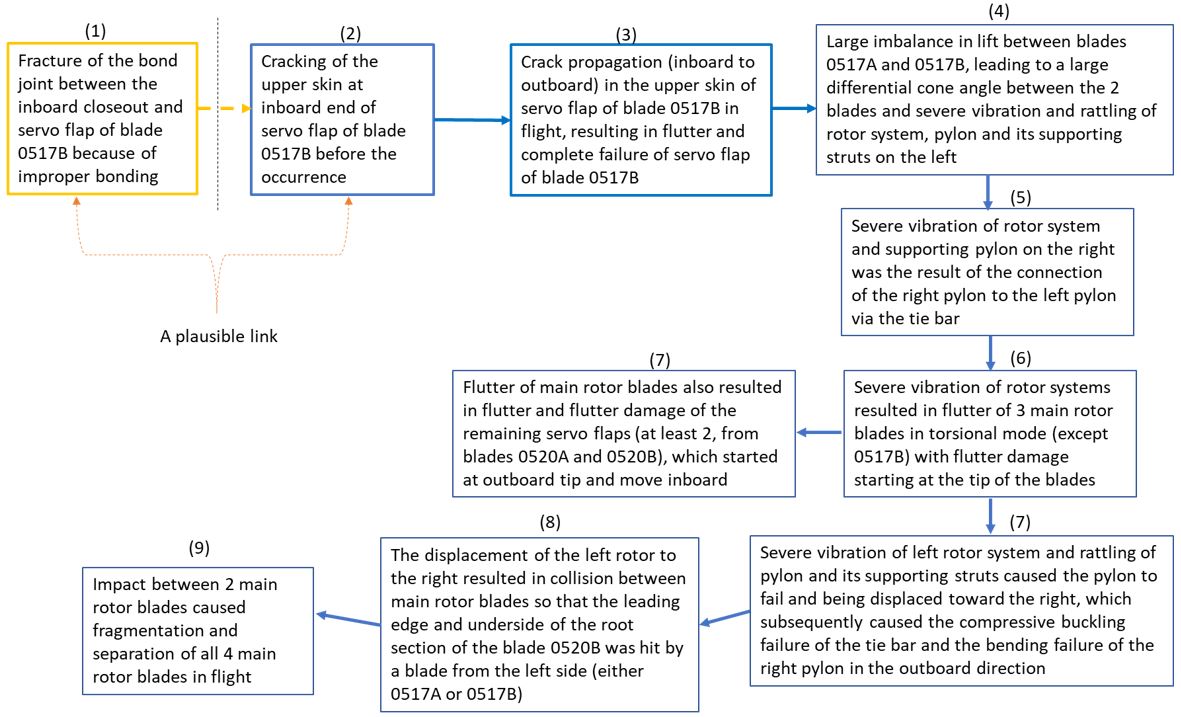
The TSB laboratory conducted various tests on the recovered portions of the main rotor blades and found that the departure of the servo flap afterbody on main rotor blade 0517B created an out-of-track condition that caused a cyclic imbalance and a sudden vibration of the left main rotor system, the flutter of the 3 other rotor blades, and the failure of the left-pylon structure. This led to the collision between a blade on the left rotor and a blade on the right rotor that resulted in the in-flight breakup of the rotor system. The investigation also found that the fracture of the bond joint between the inboard closeout and the servo flap afterbody on main rotor blade 0517B likely initiated a fatigue crack in the servo flap skin, between the D-spar and the afterbody, that progressed until the servo flap afterbody separated in flight. If the quality of the bond joint between the inboard closeout and the servo flap afterbody of Kaman K-1200 main rotor blades is inconsistent, the structural integrity of the servo flap can be compromised, leading to a risk that the servo flap will be unable to withstand normal aerodynamic loads.
While the helicopter was equipped with a 406 MHz ELT, the ELT was submerged following the helicopter’s impact with water, and no signal was received by search and rescue agencies. In this occurrence, given that the pilot was in regular radio communication with the company, the local crew was able to locate the occurrence site quickly and start searching the area. Automatically deployable ELTs may be installed in aircraft operating over water. They will detach from the aircraft and remain on the water’s surface to transmit both GPS (global positioning system) coordinates and the 121.5/406 MHz signal. Consequently, aircraft operating over water are at risk of a delayed search and rescue response if they are not equipped with an automatically deployable ELT.
The occurrence helicopter was not equipped with a flight data recorder or a cockpit voice recorder, nor was either required by regulation. Although the availability of other sources of data provided significant information for this investigation, the helicopter’s exact manoeuvring during the final moments and the time elapsed between the final data point and the actual impact with the surface could not be determined.
Following a fatal accident with no survivors or witnesses, an investigation may never be able to determine the exact causes and contributing factors unless the aircraft is equipped with an on-board recording device. This occurrence demonstrates that if cockpit and flight data recordings are not available to an investigation, there is a risk that safety deficiencies will not be identified to advance transportation safety.
Following this occurrence, Kaman Aerospace Corporation (Kaman) performed tests to verify the airworthiness of the servo flap; however, Kaman plans to further evaluate the flap’s fatigue capability.
In addition, the Kaman Model K-1200 K-MAX Maintenance and Servicing Instructions were revised on 01 June 2023. The latest revision provides added instructions for the repair of chordwise paint cracks in the bond line of the servo flap inboard closeout. The instructions note that the flap must be removed from service if the crack extends beyond the paint layer.
On 19 July 2023, the TSB issued an Air Transportation Safety Advisory Letter to Transport Canada (TC) to inform TC that, in at least 2 fatal Kaman K-1200 accidents, a main rotor servo flap experienced fatigue fractures before there was a catastrophic failure and the afterbody of the flap separated from its spar. The letter also indicated that the timeline for the progression of the flap fractures to a catastrophic failure was unknown, and that the contribution of flight loading from the phase of flight and pilot input needed further examination. TC indicated that it would monitor the industry for any additional servo flap cracking and, pending the corrective action(s) from the FAA, may take interim action if warranted.
1.0 Factual information
1.1 History of the flight
On 04 October 2021, the Kaman Aerospace Corporation (Kaman) K-1200 helicopter operated by Black Tusk Helicopter Inc. (Black Tusk) was conducting helicopter logging operations in the vicinity of Killam Bay in Jervis Inlet, British Columbia (BC). The helicopter staging area was at Agamemnon Bay, BC, located approximately 0.5 nautical miles (NM) east of Earls Cove, BC, and approximately 4 NM southwest of the logging cut blocks. Black Tusk also had an unmanned fuel barge moored along the western shoreline of Killam Bay and downslope of the logging cut blocks. It provided a nearby landing area in the event of an emergency and stored aviation fuel for refuelling the helicopter during daily logging operations (Figure 1).
A 2nd company helicopter, the Bell Helicopter 206B (registration C-FHQH), was also staged at Agamemnon Bay with a support pilot. This helicopter was primarily used for transporting the logging crews to the cut blocks and providing any additional support required for the logging operation.
At approximately 0705,All times are Pacific Daylight Time (Coordinated Universal time minus 7 hours). the occurrence pilot and logging manager met at the staging area and discussed the progress of the logging operation, any safety or production concerns, and the plan for the day. The support pilot then flew the logging manager and a log rigger to 2 separate cut blocks where they were each rigging logs in preparation for helicopter transport that day.
The occurrence pilot, with the on-site aircraft maintenance engineer (AME), proceeded to prepare the occurrence helicopter for the day. They checked the helicopter fluids, the main rotor blades, the hydraulic grapple, and the logbook. The helicopter lifted off at approximately 0755 with the grapple suspended from the belly hook on a 200-foot longline. Before departing, the pilot performed a brief hover while the AME completed an apex“The apex is where the [main] rotor cones appear to intersect in front of the aircraft.” (Source: Kaman Aerospace Corporation, Kaman K-1200 Rotorcraft Flight Manual, Revision 9 [30 June 2021], Section 10: Functional Check Flight Information, Rigging Checklist, Step 10, p. 10-13) check to visually confirm the aircraft flight controls were rigged correctly. The helicopter then departed the staging area and arrived at the 1st cut block (KIL006H)Each cut block is identified by an alphanumeric code that is used on logging permits and is recognized by the provincial government. at approximately 0800, where the logging manager was rigging logs.
The aircraft proceeded to perform 74 turnsIn the helicopter logging industry, 1 turn refers to the flight from the log pen to the pick-up site, the pickup of 1 load of logs, the return flight to the log pen, and the release of the load of logs at the log pen. from 3 different cut blocks in the Killam Bay project as follows:
- 31 turns followed by a refuelling stop at the fuel barge
- 39 turns followed by a refuelling stop at the fuel barge
- 4 turns followed by a lunch stop at the fuel barge
The aircraft landed on the fuel barge and was shut down at 1153 to avoid disturbing a nearby humpback whale, and the pilot then took a lunch break.
Approximately 49 minutes later, the aircraft departed the barge and performed 4 turns from the log pen to cut block KIL006H, situated 0.6 NM to the southeast. On the 5th turn, the aircraft departed the cut block with a load of 3 logs in the grapple at 1302:19. Approximately 75 seconds later, the aircraft dropped the logs into the log pen, entered a slow 180° turn and initiated a climb to return to the cut block. At 1303:42, following a routine radio transmission to the logging manager, the aircraft entered a rapid descent. It impacted the water within the log pen approximately 4 seconds later and sank (Figure 2).
The logging manager and rigger on the mountainside heard a loud bang that came from the log pen area. The logging manager attempted to contact the pilot repeatedly for approximately 3 minutes using a handheld very high frequency (VHF) radio. After neither receiving a response nor seeing the helicopter return, he dispatched the support helicopter from Agamemnon Bay to investigate the log pen.
On arrival at the log pen, the support pilot saw main-rotor-blade fragments floating on the water and an oil sheen on the water surface; the rest of the helicopter and the pilot were not visible. The support pilot continued to comb the surrounding area and shoreline for approximately 5 minutes before landing on the fuel barge and contacting Black Tusk’s head office to activate the emergency response plan. The support pilot then departed the fuel barge and picked up the logging manager before continuing the search at the log pen. Following several more passes and no additional signs of the pilot or helicopter, the crew departed the log pen to pick up the rigger from the northern cut block and returned to the staging area to obtain reliable cellular service, and contact search and rescue services.
At 1347:28, the logging manager contacted 911 from the staging area while the support pilot and AME returned to the log pen to continue the search with the support helicopter. The Joint Rescue Coordination Centre in Victoria, BC, then initiated a secondary search of the log pen area by acquiring assistance from multiple marine vessels and a Canadian Armed Forces Cormorant helicopter. The first vessel arrived at approximately 1407, followed by the Cormorant helicopter 7 minutes later. The marine vessels recovered fragments of all 4 main rotor blades that were floating on the water surface. The blade fragments were located outside and near the northeast edge of the log pen, and a large blade section was found in the log perimeter of the log pen. No additional sign of the helicopter was found on the water.
The occurrence helicopter was equipped with a 406 MHz emergency locator transmitter (ELT); however, no signal was received. The helicopter was located by sonar 8 days after the occurrence at a depth of 96 m and was subsequently recovered 6 days later using a dive team and an underwater remotely operated vehicle.
1.2 Injuries to persons
Table 1 outlines the degree of injuries received.
| Degree of injury | Crew | Passengers | Persons not on board the aircraft | Total by injury |
|---|---|---|---|---|
| Fatal | 1 | – | – | 1 |
| Serious | 0 | – | – | 0 |
| Minor | 0 | – | – | 0 |
| Total injured | 1 | – | – | 1 |
1.3 Damage to aircraft
The aircraft was destroyed, and several components were heavily corroded because of submersion in salt water.
1.4 Other damage
An unknown amount of aircraft fuel, engine and gearbox oils, and hydraulic fluid was released into the water.
1.5 Personnel information
The pilot held a commercial pilot licence - helicopter and a valid Category 1 medical certificate. He had completed the K-1200 Helicopter Pilot Training: Pilot Experience Level I Course on 15 April 2021 at the aircraft manufacturer’s facility. The course included:
- 6.3 flight hours, 43 landings, and 27 external load lifts during 9 solo flights in the K-1200 helicopter;
- 2.4 flight hours, 15 landings, and 17 system failures in the K-1200 flight training simulator; and
- ground school on K-1200 familiarization and pre-flight inspections.
The pilot received the Kaman K-1200 helicopter type rating (HK12) on 12 May 2021 and had accumulated 266.3 flight hours on the occurrence helicopter at the time of the occurrence.
The pilot was on his 12th consecutive day of flight duty at the Killam Bay project and had accumulated 78.9 hours over the 12 days, with an average of 6.6 flight hours per day.
The pilot’s flight duty time and rest periods were within the limitations set forth in the Black Tusk operations manual.Black Tusk Helicopter Inc., Operations Manual, Amended 01 January 2021, Section 4, Annex D: Flight Time, Flight Duty Time and Rest Period Limitations. Based on a review of the pilot’s work and rest schedule, there was no indication that the pilot’s performance was degraded by fatigue.
| Pilot licence | Commercial Pilot Licence (CPL) — Helicopter (H) |
|---|---|
| Type ratings | BH04, BH06, BH214, BH47, HK12, HU50, HU52, S315, S350, SK58T |
| Medical expiry date | 01 January 2022 |
| Total flying hours | 23 825 (approximate) |
| Flight hours on type | 272.6 |
| Flight hours in the 24 hours before the occurrence | 5.7* |
| Flight hours in the 7 days before the occurrence | 47.4 |
| Flight hours in the 30 days before the occurrence | 78.9 |
| Flight hours in the 90 days before the occurrence | 158.9 |
| Flight hours on type in the 90 days before the occurrence | 126.0 |
| Hours on duty before the occurrence | 5.5 |
| Hours off duty before the work period | 12.1 |
* The stated flight hour total is accurate at the commencement of flight operations on the day of the occurrence.
1.6 Aircraft information
The Kaman K-1200 helicopter, also commonly known as the K-MAX,The name K-MAX is a copyright of Kaman Aerospace Corporation. It is used to identify the Kaman K-1200 helicopter in multiple manufacturer publications and in industry. is designed specifically for aerial lift operations and consists of a twin, intermeshing, 2-bladed rotor system with no tail rotor (Figure 3). The narrow fuselage and single-seat configuration provide optimal visibility in forward, left, right, and vertical directions. The helicopter is equipped with a Honeywell T5317A-1Type certificate holder transferred to Ozark Aeroworks LLC on 06 May 2022. turboshaft engine and a 3-wheel landing gear.
The occurrence helicopter was purchased new from the aircraft manufacturer and imported into Canada in March 2021 with 8.4 hours of total airframe time accumulated during production flight testing. The Canadian certificate of airworthiness was issued on 17 May 2021.
The helicopter was maintained on a progressive inspection cycle in accordance with the company maintenance schedule approved by Transport Canada (TC). The progressive inspection cycle divides the 100-hour/annual inspection tasks into 4 zones to encompass related systems or components.Kaman Aerospace Corporation, Kaman Model K-1200 K-MAX Maintenance and Servicing Instructions, Revision 43 (01 June 2021), Chapter 05: Time Limits/Maintenance Checks, section 05-20-10: Progressive Inspection – Maintenance Practices, subsection A, General, p. 201. One zone is inspected every 25 hours and when all 4 zones have been inspected, all tasks of the 100-hour/annual inspection have been completed, and the cycle repeats.
The inspection task for the servo flap is in Zone 1 and it requires the servo flap to be removed for visual inspection. No cracks are allowed in the flap skins and the flap horn. The last Zone 1 inspection recorded in the journey log was 62.1 flight hours before the occurrence, on 24 September 2021.
In addition, the pre-flight inspection requires that the servo flap be visually inspected in-situ before every flight.Ibid., section 05-20-01: Preflight Inspection – Maintenance Practices, pp. 210-211. The last pre-flight inspection, recorded as a “daily” inspection in the log, was conducted by the AME after the last flight on 03 October 2021.
There were no recorded defects outstanding at the time of the occurrence.
| Manufacturer | Kaman Aerospace Corporation* |
|---|---|
| Type, model, and registration | Helicopter, K-1200, C-FZVM |
| Year of manufacture | 2020 |
| Serial number | A-94-0053 |
| Certificate of airworthiness issue date | 17 May 2021 |
| Total airframe time | 949.6 hours |
| Engine type (number of engines) | Honeywell T5317A-1 (1)* |
| Rotor type (number of rotors) | Semi-articulated intermeshing (2) |
| Maximum allowable take-off weight | 7000 pounds |
| Recommended fuel types | Jet A, Jet A-1, Jet B |
| Fuel type used | Jet B |
* The current type certificate holder is Ozark Aeroworks LLC.
1.6.1 Main rotor system
The main rotor system consists of 2 counter-rotating and intermeshing rotor systems, which are mounted side-by-side on top of the helicopter—the left rotor rotates counter-clockwise, and the right rotor rotates clockwise when viewed from above (Figure 4).
The rotors are out of phase by 90° and are tilted outward by 12.5° from the vertical axis to allow each blade to clear the opposing rotor hub. Each rotor consists of 2 blades, and each blade is controlled by an attached servo flap that is deflected by the pilot controls to produce the desired flight manoeuvre.
Each rotor shaft is supported independently by a cone-shaped aluminum-alloy pylon that is supported by 1 fore and 1 aft strut and connected to a common main transmission. According to the manufacturer, the struts are designed to support approximately 85% of the generated lift from the main rotor system. Additionally, the 2 pylons are connected to each other near the top with a tie bar.
1.6.1.1 Main rotor blades
Each main rotor blade is a monocoque cambered airfoil in which the skin of the blade is a critical part of the structural design and bears a significant portion of torsional load during the blade’s operation. Each rotor blade is constructed of a laminated-Sitka-spruce spar, a honeycomb core, and a carbon-fibre trailing edge and is enveloped with a fibreglass-composite skin (Figure 5). The width of the wood spar varies along the span of the blade. Outboard of the servo flap, the upper and lower skins are extended beyond the trailing edge to form a trailing-edge spline.
Each rotor blade has a span of 289 inches and a stainless-steel erosion guard on the outboard 114 inches of the leading edge (Figure 6). The blade section between rotor station (STA)The rotor station number refers to the distance from the centre of the main rotor hub and is recorded in inches. 115 and STA 165, inboard of the servo flap, is the elastic working section of the blade and was designed to have relatively lower torsional stiffness. As the pilot’s control input deflects the position of the servo flap, a torsional load is imparted on the blade, and this section allows the blade to twist and change the angle of attack, which subsequently produces the lift needed for the phase of flight.
The 2 rotor systems each have 2 rotor blades that are matched by the aircraft manufacturer. The blade pairings on the occurrence helicopter consisted of blades serial numbers 0517A and 0517B installed on the left-rotor hub assembly, and blades serial numbers 0520A and 0520B installed on the right-rotor hub assembly.
All main rotor blades on the occurrence helicopter were installed in new condition at the time of manufacture and had accumulated 949.6 hours of total air time.“Air time means, with respect to keeping technical records, the time from the moment an aircraft leaves the surface until it comes into contact with the surface at the next point of landing.” (Source: Transport Canada, Canadian Aviation Regulations [CARs], SOR/96-433, subsection 101.01[1]) They were subject to 2 airworthiness directives (AD) issued by the certifying authority, the Federal Aviation Administration (FAA) of the United States (U.S.), and adopted by TC:
- AD 2015-14-04,Federal Aviation Administration, Airworthiness Directive (AD) 2015-14-04 (29 June 2015). which requires removal and inspection of the blade spar before the first 3000 hours time-in-service (TIS) and thereafter at intervals not exceeding 1000 hours TIS
- AD 2010-26-11,Federal Aviation Administration, Airworthiness Directive (AD) 2010-26-11 (14 December 2010). which requires removal from service of each blade set once they have accumulated 8000 hours TIS
According to regulation, an aircraft owner must meet the requirements of all applicable ADsTransport Canada, SOR/96-433, Canadian Aviation Regulations (CARs), paragraph 605.84(1)(b). and cannot extend mandated tasks beyond the time intervals published in the AD.Transport Canada, Commercial Air Service Standards, Standard 625: Aircraft Equipment and Maintenance Standard, paragraph 625.86(8)(d). During the investigation, it was noted that the Kaman Model K-1200 K-MAX Maintenance and Servicing Instructions were revised on 01 March 2016 and increased the blade removal and inspection interval, with the 1st removal and inspection to be done at 3025 hours, and thereafter every 1025 hours.Kaman Aerospace Corporation, Kaman Model K-1200 K-MAX Maintenance and Servicing Instructions, Revision 43 (01 June 2021), Chapter 05: Time Limits/Maintenance Checks, section 05-10-00: Component Overhaul Removal Internal, subsection B, Rotor, Note 2, p. 1.
1.6.1.2 Servo flap
A servo flap is a control surface attached to the main rotor blade that is deflected by the pilot controls to change the angle of attack and resultant lift of the blade. The flap has a span of 35 inches and is pivoted on the flap rod that is mounted between 2 flap brackets extending from the rotor blade aft body at STA 190 and STA 226 with an inboard diagonal strap. The deflection of the servo flap is controlled by the control rod, which is mounted on the lower pivot point of the inboard flap horn at the inboard end (Figure 7).
The monocoque structure of the servo flap is primarily made of carbon-fibre composites with a stainless-steel leading-edge erosion guard. The key structural components are the D-spar, and the afterbody, which contains the I-beam, channel plies, and trailing-edge spline. The spar and afterbody are encompassed by a thin skin. The forward and aft channel plies are bonded to the inner surfaces of the upper and lower skins as well as to the aft surface of the D-spar and forward surface of the trailing-edge spline respectively (Figure 8).
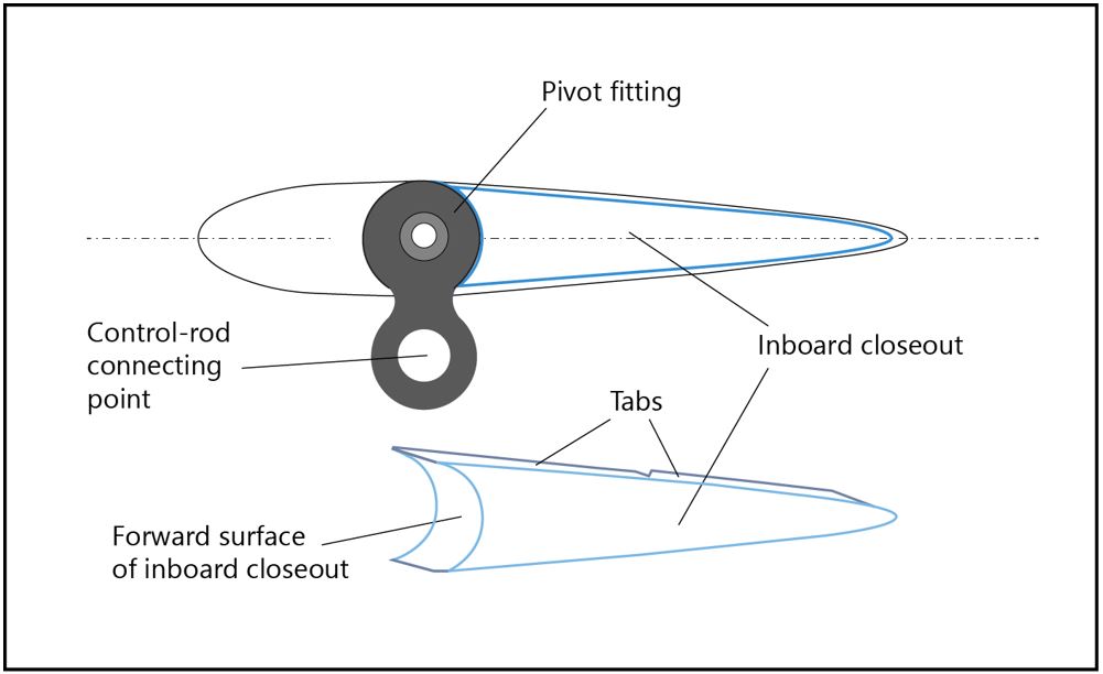
The openings in the afterbody of the servo flap at the inboard and outboard ends are sealed using closeouts (Figure 9). Each closeout is made of laminated woven-carbon composite and is inserted into the opening of the afterbody with its tabs bonded to the lower and upper skins using adhesive. Additionally, the forward concave surface of the inboard closeout is bonded to the convex surface of the pivot fitting for the flap assembly. To control the thickness of the adhesive-bond lines for optimal bonding strength, scrim cloth is placed on the bonding surface before the application of the adhesive and subsequent insertion of the closeout.
1.6.2 Engine
The occurrence helicopter’s turboshaft engine was originally manufactured on 04 December 1975 by Honeywell as a T5313B model engine. When it had 4803.7 hours total engine time, the engine was converted to a T5317A-1 on 24 August 2019. The conversion was done by Ozark Aeroworks LLC, an authorized maintenance, repair, and overhaul facility for the T53 engine. The engine has a 5-stage axial compressor, a single-stage centrifugal compressor, a 2-stage gas producer turbine, and a 2-stage power turbine. During the conversion and overhaul, all major internal rotating components were replaced, resulting in the engine cycle counts being reset to zero. The engine was also fitted with an overhauled fuel control, overspeed governor, and fuel manifold.
The engine was installed on the occurrence helicopter on 10 June 2020 by Kaman with a 0.0 hour time since overhaul.
1.6.3 Auxiliary hydraulic system
Immediately following the importation to Canada, the helicopter was modified with the addition of an auxiliary hydraulic system. The auxiliary hydraulic system was installed in accordance with Supplemental Type Certificate SR01561SE that was accepted by TC based on the approval by the FAA. The hydraulic system is a self-contained system with the pump attaching to the unused drive pad on the front side of the main transmission.
The hydraulic system on the occurrence helicopter provided hydraulic boost to actuate the hydraulic grapple via 2 hydraulic hoses that ran the length of the longline. The hydraulic hoses connect to the airframe system by 2 quick-disconnect fittings mounted on the right side of the fuselage at the same station as the cargo hook. The fittings are designed to automatically disengage if the longline is released.
During the recovery of the aircraft from the water, the investigation discovered that the hydraulic hoses for the grapple were still connected to the quick-disconnect fittings. The investigators performed a function check of the quick-disconnect release at the recovery site and noted that the hydraulic lines for the grapple disconnected from the fittings with minimal force applied by hand. The investigators also noted the presence of hydraulic fluid in both hydraulic hoses.
1.6.4 Weight and balance
During the initial certification of the helicopter as a normal-category rotorcraft in August 1994, the aircraft was approved for a maximum take-off weight of 6000 pounds with a maximum external load of 6000 pounds, for a total aircraft weight of 12 000 pounds during lifting operations. In October 1999, the FAA amended the airworthiness standards for normal-category rotorcraft, allowing the maximum take-off weight of the rotorcraft to be increased to a maximum of 7000 pounds if the number of passenger seats was not increased above what was certificated on 18 October 1999.Federal Aviation Administration, Code of Federal Regulations (CFR), Title 14, Part 27, subparagraph 27.2(b)(2)(ii)). As a result, in June 2005, the occurrence helicopter was approved for an increased maximum take-off weight of 7000 pounds without external load. The total aircraft weight with external load remained at 12 000 pounds.Federal Aviation Administration, Kaman K-1200 Type Certificate Data Sheet (TCDS) No. TR7BO, Revision 6 (23 March 2020), Notes 7, 8, and 11, pp. 4 and 5.
At the time of the occurrence, the aircraft was operating with a 200-foot longline with a hydraulically actuated grapple that no longer contained a load of logs. The assembly weighed approximately 750 pounds. The pilot refuelled the aircraft at the barge 21 minutes before the occurrence, but the investigation could not determine the amount of fuel added and the resultant total weight of the aircraft.
1.7 Meteorological information
The nearest aviation weather reporting station is at the Powell River Airport (CYPW), BC, and is located 23 NM west of the occurrence site. The aerodrome routine meteorological report (METAR) for CYPW issued at 1300 and valid at the time of the occurrence reported the following:
- Winds from 250° true (T), variable in direction from 190°T to 300°T at 3 knots
- Visibility of 30 statute miles
- Few clouds at 1100 feet, few clouds at 5000 feet, scattered clouds at 15 000 feet and overcast ceiling at 18 000 feet
- Temperature 11 °C, dew point 9 °C
- Altimeter setting 29.97 inches of mercury
Upon arrival to the occurrence site, the responding crews from the company support helicopter, the Cormorant search helicopter, and the RCMP (Royal Canadian Mounted Police) West Coast Marine Detachment vessel all reported the weather conditions as being calm winds and sea state, with high overcast cloud. Additional photographs and video collected by the investigation verified these conditions.
Weather was not considered a factor in this occurrence.
1.8 Aids to navigation
Not applicable.
1.9 Communications
Black Tusk incorporated VHF handheld radios and a specified company frequency for communication between the occurrence helicopter pilot, the riggers, and the support pilot at the staging area. The company also used satellite phones as another source of communication with phones located in the occurrence helicopter and the support helicopter and, depending on the remoteness of the cut blocks, with the riggers on the ground.
In this occurrence, good VHF radio communication was established with the support pilot and AME at the staging area, where reliable cellular phone service was available. As a result, the riggers did not have a satellite phone at the cut block.
On the day of the occurrence, operations were normal with the occurrence pilot in regular communication with the logging crew via the helicopter VHF radio system and handheld radios. There was no communication from the occurrence pilot indicating any operational abnormality throughout the day or any distress on the last transmission that was received moments before the occurrence.
1.10 Aerodrome information
Not applicable.
1.11 Flight recorders
The helicopter was not equipped with a flight data recorder or a cockpit voice recorder, nor was either required by regulation.
For automatic flight following, Black Tusk had equipped the occurrence helicopter with a Guardian Mobility G4 satellite tracker with an external antenna, which provided global navigation satellite system (GNSS)-based time, position, and movement data. The data was recorded approximately once every 2 minutes, which was too sparse to capture the helicopter’s flight path in sufficient detail for flight analysis.
The helicopter was also equipped with automatic dependent surveillance - broadcast (ADS-B), which allows aircraft to broadcast data via NAV CANADA/Aireon’s satellite-based ADS-B network. The ADS-B data included 2 altitude parameters: flight level and geometric height. The flight level is the barometric pressure altitude (based on the standard 29.92 inches of mercury), and the geometric height is the GNSS height above ellipsoidThe ellipsoid is the theoretical reference datum for the Earth’s surface that is used by global positioning systems when measuring the height above ground. as measured by the aircraft’s onboard GNSS equipment. However, different helicopter manoeuvres and an in-flight upset of some kind can affect the accuracy of either the barometric or GNSS altitude. In this occurrence, a disagreement was found between the altitude parameters for the final data point.
Additionally, the ADS-B data included ground speed, ground track, and geometric vertical rate. Experience has shown these parameters to vary considerably in accuracy because of limitations inherent in the design of the ADS-B system. In this occurrence, these limitations were further exacerbated by the aircraft’s operation at very low speed and altitude, and close to mountainous terrain.
Although the availability of ADS-B data provided significant information for this investigation, the aircraft’s exact manoeuvring during the final moments and the time elapsed between the final data point and the actual impact with the surface could not be determined.
Following a fatal accident with no survivors or witnesses, an investigation may never be able to determine the exact causes and contributing factors unless the aircraft is equipped with an on-board recording device. The benefits of recorded flight data in aircraft accident investigations are well known and documented.TSB air transportation safety investigation reports A22P0111, A21O0056, A20P0080, A19P0187, A19P0176, A18P0080, A17P0170, A16A0032, A15P0081, A14Q0148, A14W0127, A13H0002, A12W0031, A12C0005, A11H0001, A11P0106, A11C0047, A11W0048, A11O0031, A11Q0028, A11P0117, A10P0244, A09P0187, A09A0036, A07W0150, A07Q0063, A06W0139, A05C0187, A05W0137, A03H0002, A02W0173, and A01W0261.
Following an occurrenceTSB Aviation Investigation Report A16P0186. on 13 October 2016 in which a privately operated Cessna Citation 500 collided with the ground and fatally injured the pilot and 3 passengers, the Board recommended that
the Department of Transport require the mandatory installation of lightweight flight recording systems by commercial operators and private operators not currently required to carry these systems.
TSB Recommendation A18-01
In its January 2023 response to this recommendation, TC indicated that it agreed in principle with this recommendation and had published a Notice of Proposed Amendment (NPA) in December 2021 that proposed changes to the regulation mandating the installation of lightweight data recorders (LDRs) in existing aircraft and their installation in newly manufactured aircraft. TC received significant industry input and comments that resulted in a reassessment of the approach and scope of the LDR requirements. TC is developing a new and revised NPA, which was planned to be published in early 2023 with proposed regulation amendments to be published in the Canada Gazette, Part I in early 2024. However, in its most recent response dated December 2023, TC has indicated that the deliverable date for the NPA has been extended into 2024–25 for additional analysis. A timeline for publication in the Canada Gazette, Part I was not specified.
In its February 2024 assessment of TC’s response, the Board stated that it remains concerned by the potential change in approach and scope of the LDR requirements and the lengthy delays in implementation. Until the revised NPA is available for review, it is unknown if the previously proposed requirements will be preserved.
Therefore, the Board was unable to assess TC’s response to Recommendation A18-01.TSB Recommendation A18-01: Mandatory installation of lightweight flight recording systems, at https://www.bst-tsb.gc.ca/eng/recommandations-recommendations/aviation/2018/rec-a1801.html (last accessed on 29 August 2024).
1.12 Wreckage and impact information
During the search and rescue operation, nearby vessels, the RCMP West Coast Marine Detachment, and the Canadian Coast Guard successfully recovered a large section of a main rotor blade from the perimeter of the log pen and additional blade fragments from the ocean surface and near the shoreline.
The helicopter fuselage was located by sonar 8 days after the occurrence and found approximately 400 feet away from the last position recorded by the ADS-B system. An underwater remotely operated vehicle equipped with a camera was deployed. It showed that the longline with the hydraulic grapple was still attached to the belly hook of the helicopter. The longline was draped over the underwater cross-cable of the log pen at a depth of approximately 33 m from the surface, with the fuselage on the southwest side of the cable at 96 m deep and the grapple on the northeast side of the cable at 36 m deep. In this condition, the fuselage and grapple were suspended above the ocean floor.
The recovery team raised the grapple to the surface, removed the grapple from the longline and then used the longline to raise the fuselage. Once the wreckage was on the recovery barge deck, investigators tested the cargo-hook manual-release lever located on the collective and noted that the release system operated normally.
Most of the fuselage was intact, with the front of the helicopter having significant deformation and compression damage representative of a nose-down attitude during impact. Because there was also very little damage to the underside and to the sides of the fuselage, investigators determined that the aircraft entered the water nose down at a near 90° angle. According to the rotorcraft flight manual, the attitude limitation with a load is 25° nose up or nose down.Kaman Aerospace Corporation, Kaman K-1200 FAA Approved Rotorcraft Flight Manual, Revision 9 (30 June 2021), Section 2: Limitations, Flight Limitations–WITH LOAD, p 2-4.
The horizontal stabilizer remained whole with the vertical fins still on each side. However, the stabilizer was twisted downwards on the fuselage, the leading edge of the right vertical fin sustained a significant dent immediately above the stabilizer, and the lower portion of the left vertical fin was crushed.
The tail boom was whole and separated from the fuselage at the tail-boom junction; the rudder-control cable, electrical wiring, and antenna wiring were the only remaining connections of the tail boom to the fuselage. The top forward portion of the aft vertical fin was crushed in a cylindrical pattern and then buckled near the bottom back side. The rudder remained attached to the vertical fin and had limited movement.
The complete engine remained mounted to the airframe with only the front left rubber mount being separated. However, the fuselage structure fractured forward of the front mounts on both sides and resulted in the engine being angled significantly backwards. Additionally, the top of the combustion case was buckled, and the exhaust was crushed from the bottom to the top. The KaflexA Kaman proprietary driveshaft design with flexible couplings at each end. driveshaft was missing, and there was an exit hole in the engine cowling. The driveshaft couplings on each end remained attached to the engine and the transmission, and a rotational score mark was found on the fuselage frame below the transmission coupling.
The lower portion of the main transmission assembly remained attached to the fuselage. The left and right pylons had separated from the transmission at the mounting flanges and then separated from the helicopter, along with the masts, rotor hub assemblies, and supporting struts.
The nose- and right-landing-gear assemblies remained in place. The landing-gear support was severed near the left outboard end, and the left tire and strut assembly remained attached to the support only by the brake line.
The wreckage was transported to the TSB regional facility in Richmond, BC, for further examination.
1.12.1 Radial debris pattern
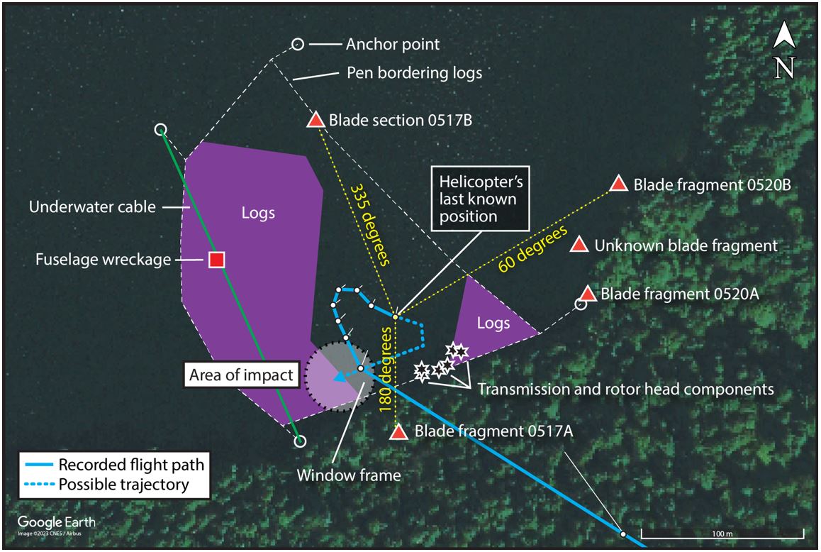
Shortly after the accident, the investigators used photographs, GPS coordinates, and visual observation to reconstruct the debris pattern and the helicopter’s possible trajectory after its last known position. Helicopter debris was located over a 228° arc surrounding the last known in-flight position of the helicopter (Figure 10).
The large section of main rotor blade was identified as blade 0517B from the left-rotor system and was located at approximately 335° and 475 feet from the helicopter’s last known position. This rotor blade impacted the log perimeter of the log pen and lodged itself in the perimeter, which provided relative certainty as to its trajectory. Two blade fragments were identified as right-rotor blades 0520A and 0520B and were found at approximately 85° and 60° respectively. A 3rd fragment was found nearby, but investigators were unable to identify which rotor blade it was from. All 3 fragment locations could only be estimated because of ocean drift.
Investigators coordinated with the U.S. National Transportation Safety Board (NTSB) to calculate an area of probability for locating parts of the 4th rotor blade (0517A). As a result, during a 2nd deployment to the site, in January 2022, the tip of rotor blade 0517A was successfully located on the forested hillside at approximately 205° and 750 feet from its paired rotor blade 0517B. The blade tip helped identify another blade fragment that was found on the ocean surface as being part of the lower skin of blade 0517A.
Most of the recovered components associated with the main rotor system and transmission were clumped together underwater between 123° and 160° near the shoreline and approximately 160 to 185 feet away from the helicopter’s last known position.
Lastly, a portion of the cockpit window frame from the front windscreen was also located underwater at approximately 203° and 175 feet from the helicopter’s last known position and approximately 120 feet from the nearest main rotor system and transmission debris. The cockpit window frame is a structural portion of the forward fuselage. As a result, the investigation determined that the frame location indicated the approximate position of impact within the log pen.
1.12.2 Examination of the engine
A preliminary engine examination was conducted by investigators at the TSB’s facility in Richmond, with the assistance of the aircraft and engine manufacturers. The 2 engine control linkages from the cockpit to the fuel control were determined to be continuous at the time of the occurrence. The fractures and separation of the engine control tubes in the fuselage were consistent with overload forces from the impact. Investigators also noted there was fuel present in the engine fuel supply line and the oil filter did not contain any debris.
The engine was then shipped to the engine manufacturer’s facility, where it was disassembled and examined with representatives of the engine manufacturer, the NTSB, and the FAA present.
All 5 stages of the axial compressor exhibited a combination of blade damage consisting of airfoil impact damage, missing material, and bent airfoils in the direction opposite of rotation. In addition, the compressor rotor blades of the first 3 stages were found separated from the blade root—all 34 from the 1st stage, 7 from the 2nd stage and 1 from the 3rd stage—which is consistent with high-speed engine rotation during water ingestion. All compressor blade failures were due to overload with no evidence of pre-existing fatigue fractures.
The gas producer turbine nozzles contained minor metallic splatter that is consistent with high temperatures being present in the combustor section when metallic debris entered the airstream.
The cumulative engine damage observed during the examination is consistent with the engine operating at the time of impact.
1.12.3 Examination of the main rotor system, main rotor blades, and associated components
The main rotor system and associated components were examined at the TSB Engineering Laboratory in Ottawa, Ontario, with representatives from the aircraft manufacturer, the NTSB, and the air operator present.
1.12.3.1 Examination of the main rotor transmission
During the wreckage recovery, the left and right pylons were found separated from the main transmission. The right-rotor pylon, mast, hub assembly, and supporting struts were recovered from the debris field. The left-rotor upper pylon, rotor shaft, hub assembly, and supporting struts were not recovered except for a small remaining portion of the left forward strut that was still attached to the fuselage.
The main transmission could not be rotated. The transmission casings were partially disintegrated after immersion in salt water and no longer contained all the internal components. Perforations of the transmission case were observed, and white cement-like deposits filled the cavities within the gearbox.
The transmission clutch assembly could not be rotated, but after disassembly, cleaning and reassembly, the clutch operated normally.
No pre-existing anomalies related to the transmission assembly were identified during the detailed examination.
1.12.3.2 Examination of the main rotor pylons
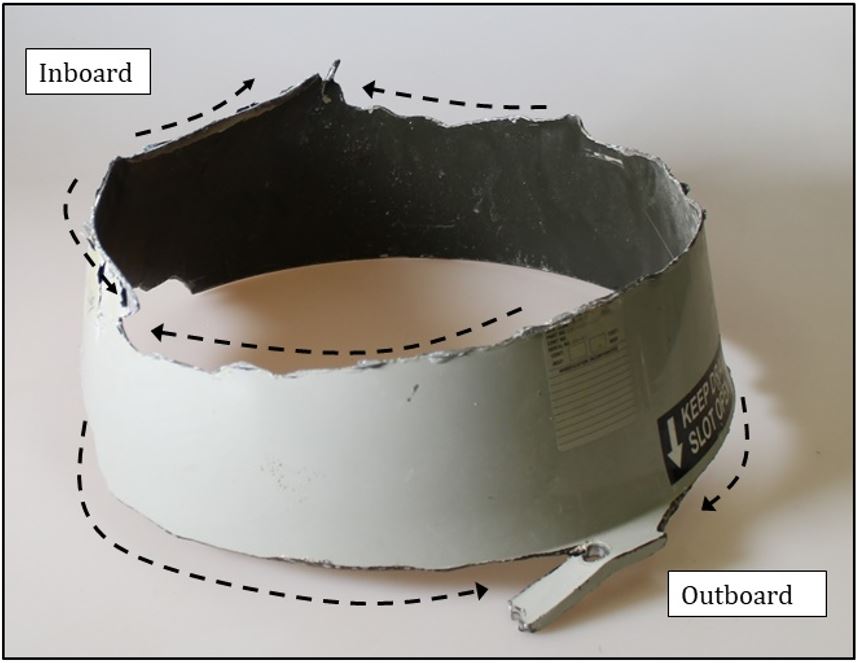
The broken pieces recovered from the left pylon failed primarily through multiple circumferential fractures. This is consistent with dynamic loading in which the load direction is rapidly changing. The surfaces did not show any sign of compression buckling or impact with other objects. Further examination of the circumferential fracture lines revealed several sharp turning points (or ligament fractures), which is indicative of 2 fracture lines coming together from opposite directions at slightly different levels (Figure 11). The fractures 5 inches above the bottom of the pylon appeared to have propagated from both inboard and outboard locations, and the fractures at the bottom of the pylon, from inboard to outboard.
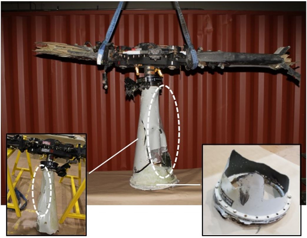
The right-rotor pylon, hub, and planetary-gear assembly were recovered. The pylon was broken into 2 pieces and had separated from the main transmission because of the failure of 16 of 21 bolts on the connecting flanges (Figure 12). The 5 bolts that had not failed were located on the outboard side and retained a small section of the connecting flange from the transmission. The 2 pylon pieces had been separated from each other by an inboard transverse fracture that propagated outboard, with half of the inboard fracture exhibiting a 45° shear lip that is consistent with tensile failure in the vertical direction. In addition, the outboard surface of the pylon exhibited compressive buckling due to compression in the vertical direction. Combined, the right-pylon damage characteristics are consistent with the pylon being bent outboard, causing the inboard fracture in tension and the outboard buckling in compression.
The tie bar connecting the 2 pylons showed compressive buckling and was fractured because of compression in its longitudinal direction. This is consistent with the left pylon being displaced inwardly toward the right pylon before the right pylon failed in the outboard direction.
Examination of the fracture surfaces of the available supporting struts and the remnants of the lower connecting brackets indicated that the struts and brackets failed in overstress. No sign of pre-existing damage or defect was found on the struts.
1.12.3.3 Examination of the main rotor blades and servo flaps
The examination identified that damage to the tips of 3 main rotor blades (0517A, 0520A, and 0520B) and to 2 servo flaps (from blades 0520A and 0520B) exhibited similar characteristics to each other, but different characteristics from the 4th blade, 0517B, and associated servo flap (Appendix A). In particular, the bond joints of 3 rotor blades and 2 servo flaps had completely fractured at the trailing edge and part of the aft-body skins were torn off, which is consistent with damage due to flutter.
Flutter is the uncontrolled cyclical motion of twisting and bending of a rotor blade when a rotor system vibrates from an imbalance. It will cause the blade to move up and down or twist back and forth because of aerodynamic forces. Flutter becomes problematic when the rotor system design cannot dampen out the energy of the oscillations that in turn increase in amplitude until the limitations of rotor system structural design are exceeded and the rotor system catastrophically fails. Because of the violent twisting that can occur, flutter introduces excessive shear stress in the trailing-edge bond joint of a rotor blade and, once the trailing-edge bond joint fails and opens up, the skins of the blade aft body do not have sufficient rigidity to maintain their shape against aerodynamic forces and are torn off in high-velocity air flow.
1.12.3.3.1 Rotor blade 0517A
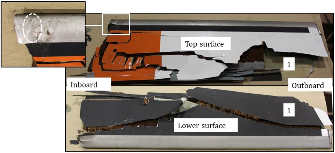
The investigation recovered only 60 inches of the tip of rotor blade 0517A, with most of it found on the forested mountainside and a lower-skin fragment found in the water. The upper skin was broken into multiple small pieces, and the upper surface of the leading-edge steel guard exhibited a diagonal crease that is consistent with torsional damage (Figure 13).
The trailing-edge bond joint had fractured and opened up completely. Examination of the fracture surface on the separated lower-skin piece indicated there were 2 failure modes:
- interlaminarAn interlaminar fracture is defined as a fracture “in the laminate plane, in which the layers have separated.” (Source: E. Greenhalgh, Failure Analysis and Fractography of Polymer Composites [Woodhead Publishing Limited, 2009], p. 37) fracture between the fibreglass lower skin and carbon-fibre layer at the trailing-edge bond joint; and
- intralaminarAn intralaminar fracture is defined as a fracture “through the thickness in which only matrix, or fibre/matrix interfaces have been broken.” (Source: Ibid.),A polymer composite is a bonded microstructure that features a matrix, functioning as an adhesive, that bonds all fibres together in a designed pattern. fracture within the carbon-composite trailing-edge strip.
The examination revealed that the inner surface near the trailing-edge tip of the fibreglass lower skin piece had hardly any adhesive present, indicating that the adhesive in this area of the trailing-edge bond joint had failed and resulted in the interlaminar fracture.
Microscopic examination, using a scanning electron microscope (SEM), of the intralaminar-fracture surface on the trailing-edge strip revealed the presence of cusps, a matrix fracture feature that indicates the failure mode involved was shear.E. Greenhalgh, Failure Analysis and Fractography of Polymer Composites (Woodhead Publishing, 2009), Chapter 4: Delamination-dominated failure in the polymer composite, pp. 186-188. The cusps appear to be rolled or deteriorated, which indicates the failure occurred in a progressive manner through cyclic loading rather than instantaneous overload.
The servo flap from blade 0517A was not recovered.
1.12.3.3.2 Rotor blade 0517B
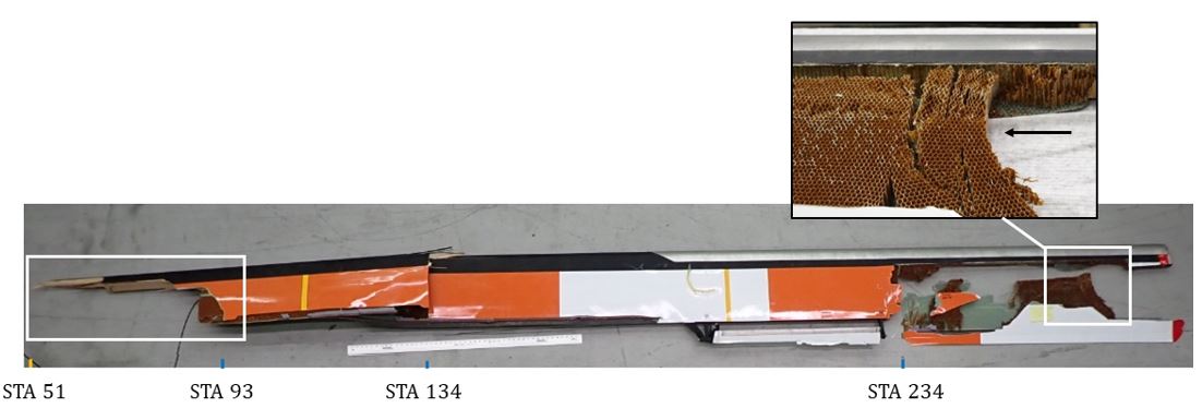
The outboard section of rotor blade 0517B was recovered and had separated from its root section at STA 51. The laminated-wood spar had fractured over a range between STA 51 and STA 93. The fracture also included spar delamination resulting in the fractured end of the wood spar being shaped like a toothpick. This shape is consistent with a forward-bending fracture with significant centrifugal force acting on the blade. The spar fractured in a 2nd location, at STA 134, showing signs of limited delamination.
The outboard leading-edge steel guard did not exhibit any sign of impact or deformation, and a significant portion of the blade body of the tip section was missing. The remaining honeycomb core was torn off and compressed in the longitudinal inboard direction. The trailing edge of the outboard tip section separated from the blade at STA 234, but the trailing-edge bond joint remained intact (Figure 14).
Of the recovered servo flaps, the flap from rotor blade 0517B was the only one whose afterbody completely separated from the D-spar. The flap afterbody was not recovered. Visual examination of the remaining servo flap upper and lower skins (consisting of the outer, inner, and forward channel plies) revealed that the spanwise fractures and failures had different features.
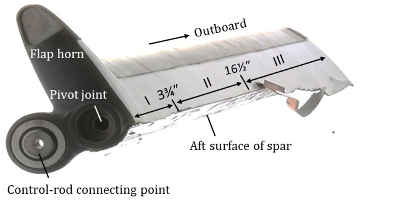
The upper skin can be divided into 3 zones of failure (Figure 15) as measured from the inboard end:
- Zone I was up to 3¾ inches.
- Zone II was 3¾ to 16½ inches.
- Zone III was 16½ to the full 35 inches spanwise width to the outboard end.
In Zone I, the outer ply fractured approximately 1/8 inch aft of the spar whereas the inner and channel plies of the upper skin fractured right where they meet with the spar. There was no indication that the forward channel ply peeled off from the aft surface of the spar. In Zone II, the fracture of both outer and inner plies of the upper skin occurred at the aft surface of the spar, and the forward channel ply had partially peeled off from the aft surface of the spar. In Zone III, the fracture of the upper skin occurred approximately 1 inch aft of the spar, with secondary fractures going in opposite directions.
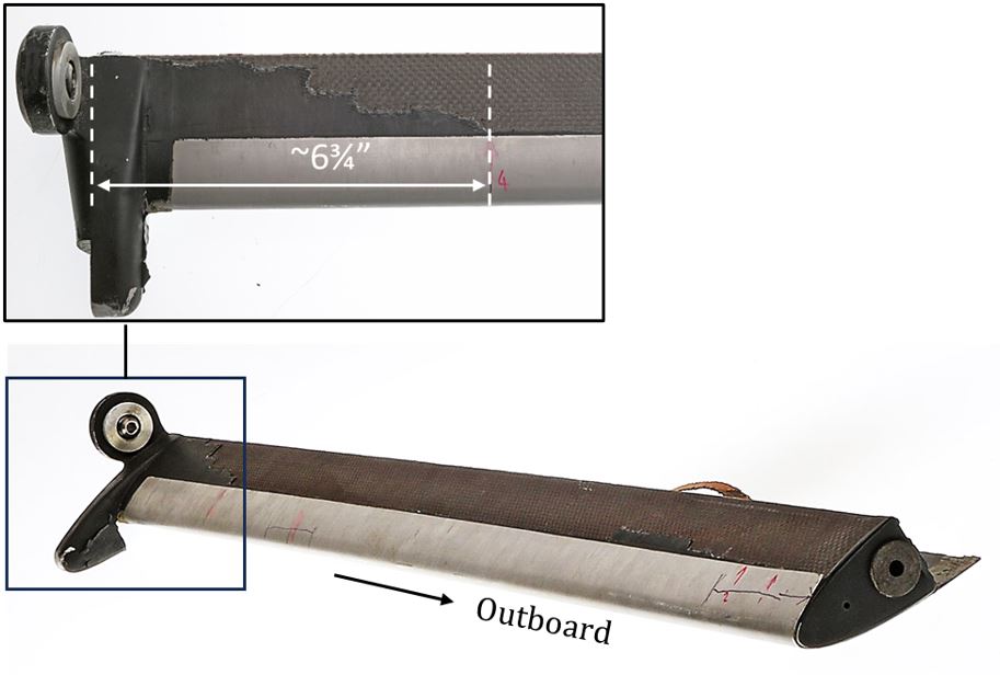
The lower skin had peeled off from the spar’s lower surface except for a 6¾-inch section at the inboard end (Figure 16). The peeling was progressive as it propagated outboard. Additionally, the forward channel ply remained bonded to the aft side of the spar and had fractured at its lower corner where it transitions from the inner ply of the lower skin to the aft side of the spar.
SEM examination of the upper skin at the inboard end of the servo flap revealed evidence of extensive rubbing of the fracture surfaces as follows:
- A pile of compacted fine powder and rounded fibre ends in the outer ply
- Fractured fibre ends worn down and barely visible in the forward channel ply
- Rolled matrix cusps, which are associated with fatigue failure of polymer matrix compositesIbid., Chapter 5: Fatigue failures of polymer composites, pp. 248 and 264.
In comparison, the fracture surface of the upper skin at the outboard end of the servo flap did not show any evidence of rubbing throughout the fracture surface, which is consistent with an instantaneous fracture and separation.
SEM examination of the lower skin at the inboard end of the flap revealed that the outer-ply fibre bundle was not flush with the rest of the fibre bundles. The bundle was also covered with a deposit of a foreign material containing elements commonly associated with environmental contamination, which indicated the damage was pre-existing.
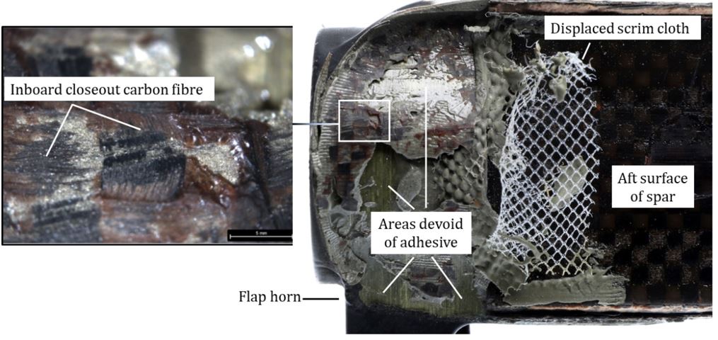
Visual examination of the convex surface of the flap’s pivot fitting showed the scrim cloth was not present in 90% of the bonding area on that surface and was mostly clean of adhesive, indicating it was displaced before the adhesive was applied. Furthermore, more than 50% of the bonding-area surface was devoid of adhesive with no sign of fracture features. Microscopic examination using an optical microscope of the bonded areas revealed that, in addition to the bond-joint failure, the inboard closeout sustained intralaminar fractures of the carbon fibre composite as indicated by fibre remnants from the closeout on the flap horn (Figure 17).
1.12.3.3.3 Rotor blade 0520A
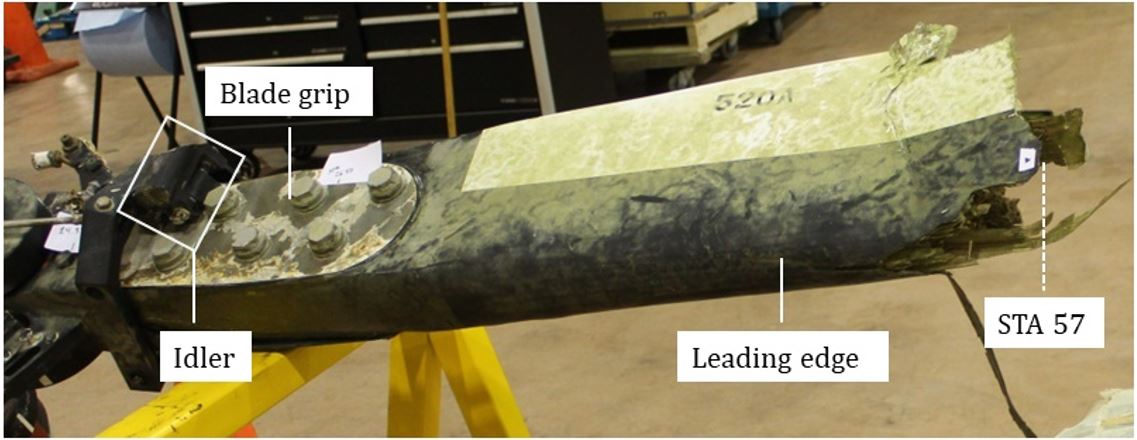
The root section of rotor blade 0520A remained attached to the grip of the main rotor blade, and the blade separated at STA 57. No impact sign was observed on the grip, the root, or the leading-edge guard of the blade (Figure 18).
The upper surface of the steel leading-edge guard was buckled from compression in the vicinity of the servo flap, and wood fibres were pushed into the mating fractures further inboard on the blade spar, which indicates the blade was bent upward during the failure sequence.
The tip section of the blade lost most of the trailing edge and a good portion of the upper and lower skins. Damage was the worst at the tip and decreased gradually going inboard. Examination of the available trailing-edge lower skin from the tip section showed that the bond joint between the lower skin and the upper skin had fractured.
The servo flap from blade 0520A had a similar damage pattern as the rotor blade, with the skins being torn off at the outboard tip and damage decreasing going inboard. Furthermore, what remained of the trailing edge also showed that the bond joints had fractured between the lower skin and the upper skin.
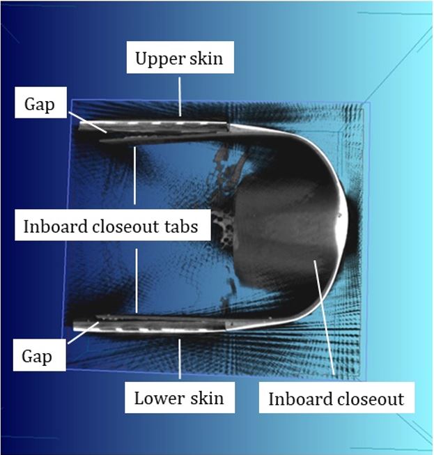
The flap’s inboard closeout had a crack in the bond joint between the closeout and the flap. The bond joint was inspected using the CT scan (computed tomography scan) technique and the scan revealed a gap between the concave surface of the closeout and the convex surface of the flap’s pivot fitting. The scan also showed that the 2 tabs of the closeout were largely not in contact with the respective mating inner surfaces of the servo flap skins, which resulted in a reduced bonding area from what was available.
With time, cracks can lead to skin fractures because of potential delamination caused by physical and mechanical properties of laminate composites,There is generally an undesired high-stress/strain concentration at the free edge of laminated composite structures, often referred to as free-edge effect, due to the anisotropic nature in physical and mechanical properties of the laminate composites, which tends to cause delamination among other damage to the structure. (Sources: Mittelstedt, C. et al, “Free-Edge Effects in Composite Laminates—A Review of Recent Developments 2005–2020”, Applied Mechanics Reviews, Transactions of ASME, Vol. 74, [18 January 2022], and Herakovich, C. T. et al, “Free strain concentration in real composite laminates: Experimental-Theoretical correlations”, Interim report 46–NASA-Virginia Tech Composite Program [under NASA Cooperative Agreement NCC1-15] [July 1984]). vibrations, and material degradation from exposure to environmental elements.
1.12.3.3.4 Rotor blade 0520B
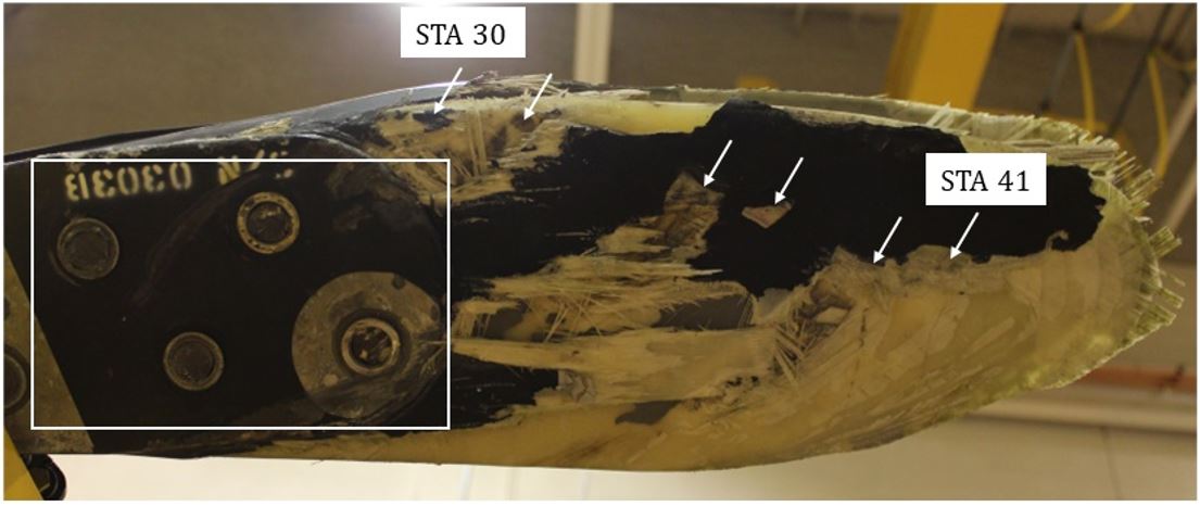
Like rotor blade 0517B’s spar, the fracture end of rotor blade 0520B’s spar was shaped like a toothpick (STA 32). A piece of wood from the laminated spar had pulled out and exposed a dark brown area on the fracture surface, indicating the adhesive had failed between the wood.It is assumed that the adhesive used in the wood joint of the laminated wood spar is brown in colour. Immediately outboard of the separation, a semi-circular dent was found on the lower surface, just below the leading edge. The diameter of the dent is consistent with the circular section of a rotor blade idler,The main rotor blade idler forms part of the servo flap control system. which is located on the top of all the blade grips.
The root section of blade 0520B remained connected to the main rotor grip. The blade’s lower surface had a set of patterned impact marks between STA 30 and STA 41 that were observed to be from the leading edge to the trailing edge and from outboard to inboard. The spacings between those impact marks are consistent with the spacings between the bolt heads on each rotor-blade grip. Most of the blade’s bolt ends on the blade’s grip had also been sheared off (Figure 19).
Immediately outboard of the servo flap, the upper skin had a V-shape partial fracture that started from the trailing edge. It is indicative of the blade tip bending forward relative to the inboard section. Further outboard, the leading edge was fractured completely and exhibited compression and twisting deformation at the fracture line. The upper and lower skins were partially torn off the blade tip, with the bond joints fractured completely at the trailing edge.
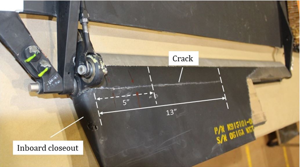
The servo flap of blade 0520B had similar damage to that of blade 0520A. The skins at the outboard tip were torn off and the remaining portion of the servo flap fracture surface showed a trailing edge bond joint fracture between the lower skin and upper skin. However, visual examination of blade 0520B’s servo flap showed a continuous crack in the bond joints between the flap inboard closeout and the lower skin. The crack was determined to be 13 inches long, of which 5 inches went through all the lower-skin plies and the remaining 8 inches went through only the lower-skin outer ply (Figure 20).
Just like for blade 0520A’s servo flap, a CT scan was performed on the bond joint of the inboard closeout of blade 0520B’s flap. It revealed a similar gap between the 2 tabs of the closeout and the respective mating inner surfaces of the skins (Figure 21).
The flap was subsequently cut along the servo flap chord line 2 inches from the inboard end to examine the integrity of the bonding joint with the servo flap. The investigators discovered that the bond joint between the closeout’s concave surface and the pivot fitting’s convex surface had fractured completely. In addition, the scrim cloth was displaced out of the bonding area, and there was evidence of intralaminar fractures of the carbon fibre composite similar to those observed on flap 0517B.
1.12.3.4 Examination of the servo flap brackets and control rods
Main rotor blades 0517B, 0520A, and 0520B showed impact damage from the servo flap on the inboard flap brackets, but no damage on the outboard brackets. In all cases, the multiple impact dents on the brackets corresponded to both the location and the damage to the head of the control-rod attaching bolts.
The control rods for the servo flaps on blades 0517B and 0520B were bent along the longitudinal centre of the rod, which was consistent with compressive buckling. The control rod for blade 0520A’s flap was not bent.
Investigators conducted a test on main rotor blade 0520A to see at which deflection angle the head of the control-rod attaching bolt would contact the servo flap inboard bracket. With the associated flap attached to the main rotor blade, the control-rod bolt head contacted the bracket when the servo flap was deflected with the trailing edge down by approximately 30° relative to the chord of the main rotor blade. The servo flap is designed to normally operate with trailing edge up.
1.12.4 Examination of the caution advisory light panel and the master caution panel
The caution advisory light panel and master caution panel were recovered and examined at the TSB laboratory. The caution advisory light panel contained 24 labelled lights, each with 2 internal lightbulbs, and the master caution panel contained 3 labelled switches, each with 4 internal lightbulbs. The observed large-scale filament damage was consistent with a high-energy single impact of the helicopter with the water surface.
The following 7 caution lights were likely lit at the time of impact:
- Caution advisory light panel:
- XMSN PRESS (main-transmission oil pressure)
- XMSN LOW (main-transmission oil level)
- ENG PRESS (engine oil pressure)
- ENG LOW (engine oil level)
- GENERATOR
- Master caution panel:
- MASTER CAUTION (indicates other caution lights are lit)
- ROTOR (main rotor low rpm)
The main-transmission and engine oil systems each have an unpressurized oil reservoir that is located above the cockpit and rely on gravity to maintain a constant feed of oil to the oil pressure pump. While the data indicates that the oil-level and oil-pressure caution lights were likely lit on impact for both systems, the investigation was unable to determine the effect that the main-transmission breakup and the severe nose-down and slightly inverted attitude had on the oil systems and the resulting indications.
1.13 Medical and pathological information
1.14 Fire
There was no indication of fire either before or after the occurrence.
1.15 Survival aspects
At the time of the occurrence, the pilot was wearing a flight helmet and the 5-point safety harness comprised of a lap strap, shoulder harness, and a tiedown strap. The pilot was not wearing a personal floatation device, nor was he required to by regulation.
The accident was not survivable because of the impact forces involved.
1.15.1 Emergency locator transmitter
The helicopter was equipped with a Kannad AF-H Integra 406 MHz ELT. No signal was received, but the investigation was unable to determine if it was a result of an ELT malfunction or submersion in water.
An automatically deployable ELT can be installed in aircraft operating over water. In the event of an accident, it will detach from the aircraft and remain on the water’s surface to transmit both the GPS coordinates and the 121.5/406 MHz signals to rescue services. This device was not installed on the occurrence helicopter nor was it required to be by regulation.
1.16 Tests and research
1.16.1 Main rotor blade and servo flap testing
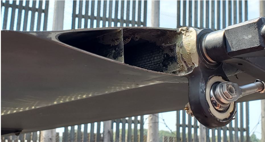
On 08 June 2022, the aircraft manufacturer performed a whirl testA whirl test consists of main rotor blades being mounted on a whirl tower that allows rotation of the rotor blades and measurement of aerodynamic forces during selected rotation speeds and control inputs. of a main rotor blade set at its facility to “demonstrate the aeromechanical stability of the [servo] flap in a degraded condition.”Kaman Air Vehicles, Memo D490/SG-3489, K-MAX Servo-Flap Whirl Test with Inboard Closeout Removed (29 June 2022). For the test, 1 servo flap inboard closeout was removed on 1 of the 2 blades (Figure 22). No damage to simulate cracking was introduced into the servo flap for the purpose of this test.
The whirl test was conducted at the power-on rotational speed for the main rotor of 270 rpmFederal Aviation Administration, Kaman K-1200 Type Certificate Data Sheet (TCDS) No. TR7BO, Revision 6 (23 March 2020), p. 1. with incremental changes in the collective pitch of the servo flap to a maximum collective pitch setting of 61%—no cyclic control input was induced to protect the test stand. The test data provided a comparison of the vibratory loadThe vibratory load is the resultant aerodynamic load applied to the servo flap as the airflow is altered over the flap because of induced vibration. on the servo flap between the whirl test configuration with the missing inboard closeout and the K-MAX’s FAA certification flight test with intact rotor-blade assemblies in an out-of-ground-effect hover with an external load (Table 4).
| Type of test | Whirl test | Certification flight test |
|---|---|---|
| Servo flap inboard closeout | Removed | Installed |
| Collective pitch setting (%) | 61 | 69.75 |
| Servo flap vibratory load (lb) | 43.45 | 18.87 |
Despite the collective pitch setting being 8.75% lower on the whirl test blade assembly, resulting in lower aerodynamic loading, the vibratory load on the servo flap increased by more than 130% when compared to the certification flight test because of the missing inboard closeout.
1.16.2 Dynamic simulation
The TSB laboratory built a computer-generated dynamic simulation modelAutodesk Inventor Professional software (Version 2022) was used for the simulation. to check the following:
- The magnitude of the unbalanced load introduced into the rotor system and the rotor-blade track deviation between the 2 rotor blades when one of the servo flaps fails.
- The main rotor-system condition that allowed the bolts of a left-rotor-blade grip to impact the right-rotor blade 0520B between STA 30 and STA 41.
1.16.2.1 Unbalanced loads and rotor blade track deviation
The dynamic simulation modeled 1 pair of the aircraft’s main rotor blades connected to 1 common rotor shaft with a teeter pin. The lead-lag function of the aircraft’s main rotor mechanical friction dampers and vertical lag pins was not included in the simulation for simplification of the model.
The approximate weight of a partially fuelled helicopter with a longline and empty grapple was used to calculate the lift produced by the main rotor blades. The main rotor rotation speed was set to the normal rpm for the helicopter at 270, and the lift was applied 40 inches from the rotor blade tips. The simulation was then based on the assumptions that the weight of the helicopter remained constant, and that the rotor blade would produce negligible lift when the servo flap failed.
The simulation started with the main rotor system and servo flaps functioning normally. A lift force equivalent to the 2gThe simulation used a lift force equivalent to a load factor of 2g on the helicopter to understand the change of the load in the horizontal plane (lateral load) on the rotor shaft when the lift force is increased.,g is a unit of measurement of the force resulting from vertical acceleration due to gravity. An acceleration of 1g is 9.8 m/s². vertical acceleration of the helicopter was applied equally to each blade to establish the baseline rotor blade track and load on the rotor shaft. The simulation was started a 2nd time and emulated a servo flap failure by reducing the lift on 1 rotor blade to 0.
The simulation indicated that, in the case of a servo flap failure, the 2 blades are out of track by a significant margin and cause a large cyclic and unbalanced lateral load on the rotor shaft. The unbalanced lateral load then oscillates in a circular pattern as the rotor blades rotate around the rotor shaft, which imparts the increased lateral load on the pylon and supporting structures (Table 5). According to the manufacturer, there was no test or analytic modeling of the dynamic structural response of the pylon and its support struts to lateral loading because it was not required by the aircraft certification.
| Functional status of the servo flaps | Rotor blade vertical track deviation (m) | Lateral load on the rotor shaft (N) |
|---|---|---|
| Both servo flaps functioning normally | 0 | 0 |
| One failed servo flap | 0.559 | 5000 |
The magnitude of the rotor blade track deviation and of the unbalanced lateral load on the rotor shaft is highly dependent on the amount of lift that the rotor blades are commanded to produce at the time of the flap failure. The occurrence helicopter was in the initial climbing phase to return to the cut block, and the rotor blades were producing an increased lift force to achieve a greater than 1g vertical acceleration for the helicopter when the servo flap failed. However, due to the lack of flight data, the investigation was unable to simulate the precise lift force and the resultant rotor blade track deviation and unbalanced lateral load applied to the rotor system.
1.16.2.2 Rotor blade contact
The dynamic simulation to examine the rotor blade contact that was observed on the root section of blade 0520B (see Figure 19 in Section 1.12.3.3.4 Rotor blade 0520B) was built the same as the occurrence helicopter—the 2 rotor shafts were set 12.5° offset from the vertical axis and 48 inches apart at the top of the shafts with rotor blades of the correct length and chord. The right and left rotor systems were set to be perpendicular to each other to reflect the phase differential during the rotor blade rotation. The rotation speed was then set to 270 rpm again.
The simulation indicated there are 2 cases in which the bolts of a left-rotor blade could possibly contact the underside of a right-rotor blade because of a reduction in vertical clearance between them. In both cases, the impact locations on the right-rotor blade occurred between STA 55 and STA 75, which is approximately 25 inches outboard of the impact zone found on the occurrence aircraft’s right-rotor blade 0520B.
Additionally, the simulation demonstrated that, based on the direction of rotation of the rotor blades, the direction of the marks on right-rotor blade 0520B were consistent with contacting left-rotor blade 0517B. However, the simulation was unable to determine the effect the displaced pylons had on the direction of the impact.
1.16.3 TSB laboratory reports
The TSB completed the following laboratory reports in support of this investigation:
- LP128/2021 – Surveillance Data Analysis
- LP148/2021 – NVM [non-volatile memory] Data Recovery
- LP154/2021 – Annunciator Analysis
- LP021/2022 – Main Rotor Transmission Examination
- LP049/2022 – Failure of Main Rotor Blades and Servo Flaps in K-MAX-Helicopter
1.17 Organizational and management information
Black Tusk is a privately owned company based in Squamish, BC, and holds an air operator certificate for operations conducted under Subpart 702 (Aerial Work) and Subpart 703 (Air Taxi Operations) of the Canadian Aviation Regulations. The company specializes in heavy-lift operations, including heli-logging, precision construction, and aerial firefighting. It also provides air-taxi services for the local region.
The company’s fleet at the time of the occurrence consisted of 3 Bell 214B-1 helicopters, 2 Bell 206B helicopters, 1 Airbus AS350B-2 helicopter, and 1 Kaman K-1200 helicopter.
The company is also a TC-approved maintenance organization with the following capabilities:
- Non-specialized work on all fleet aircraft types
- Sheet metal repair and modification on all fleet aircraft types
- Component overhaul for Bell 206A/B and 214B series helicopters
- Engine specialized maintenance for Honeywell T5508D engine
1.18 Additional information
1.18.1 National Transportation Safety Board investigations
On 16 June 2010, a Kaman K-1200 helicopter (registration N134WC) crashed approximately 5 miles west of Donnelly, Idaho, U.S. The helicopter was conducting heli-logging operations and actively lifting a large log when 2 eyewitnesses saw what appeared to be an outboard section of 1 rotor blade separate, followed by a loud bang. Control was lost and the helicopter impacted terrain. The pilot was fatally injured.
The NTSB Aviation Accident Final ReportNational Transportation Safety Board (NTSB), Aviation Accident Final Report WPR10FA295 (08 March 2012). determined the probable cause of the accident was the collision of 2 counter-rotating main rotor blades for undetermined reasons, which resulted in a loss of control.
On 24 August 2020, a Kaman K-1200 helicopter (registration N314) crashed near Pine Grove, Oregon, U.S. The helicopter was conducting water bucket operations when communication with the pilot was lost. The onboard GPS indicated that the helicopter was slowing down and descending on approach to the dip site on the White River before the occurrence. A 2nd helicopter located the wreckage and found the fuselage resting on the right side with the longline still attached to the cargo hook. The blades of the left main rotor were separated at the blade roots. Large sections were located approximately 500 and 560 feet from the main wreckage whereas portions of the blades of the right-main rotor remained attached to the rotor hub and remained within 81 feet of the main wreckage. The pilot was fatally injured.
The NTSB Aviation Accident Final ReportNational Transportation Safety Board (NTSB), Aviation Accident Final Report WPR20LA283 (26 April 2023). determined the probable cause of the accident was the in-flight failure of the servo flap on a left-rotor blade, which resulted in the collision of the 2 intermeshing rotor systems and subsequent in-flight breakup.
1.18.2 Other occurrences
The aircraft manufacturer received reports of 3 in-flight servo flap incidents that resulted in successful landings. These incidents were recorded in K-1200 Routine Field Service Reports.
In April 2004,Kaman K-1200 Routine Field Service Report, 03 April 2004. a Kaman K-1200 helicopter was conducting logging operations and, when it was near the log pen, the pilot felt a strong vibration accompanied by a banging noise. The pilot was able to successfully land the helicopter and, upon inspection, it was determined that the aft bolt of the outboard servo flap bracket had failed.
In April 2009,Kaman K-1200 Routine Field Service Report, 06 April 2009. a Kaman K-1200 helicopter was in a hover and preparing for an external lift during seismic operations when the helicopter experienced high levels of vertical vibration accompanied by a banging noise. It became difficult to control and was spinning to the left. The pilot released the longline and was able to successfully land the aircraft with no damage to the airframe. Following shutdown, a servo flap of the left-rotor system was missing and had separated from the servo flap brackets.
In August 2014,Kaman K-1200 Routine Field Service Report, 11 August 2014. a Kaman K-1200 helicopter was hovering with a 5000-pound load of water over a fire when the left-rotor blade set began tracking erratically, which induced a significant vibration and reduced handling characteristics. The pilot released the water and slowly navigated to a landing site by making small adjustments to the flight controls, power settings, and rotor rpm. The helicopter landed successfully and, similarly to the 2004 incident, the post-flight inspection revealed that the aft bolt of the outboard servo flap bracket had failed, which resulted in the servo flap being connected only to the inboard bracket.
Following the 2014 occurrence, the aircraft manufacturer released a mandatory Service BulletinKaman, Aerospace Corporation, Service Bulletin No. 114, One Time Torque Check of Inboard and Outboard Flap Brackets (16 April 2014). that required a one-time torque check of the mounting hardware of the inboard and outboard servo flap brackets.
In all 3 occurrences, it is unclear what role or effect the pilot inputs had in preserving the integrity of the main rotor system to enable a successful landing. The rotorcraft flight manual contains no emergency procedure for pilots to respond to an in-flight servo flap failure.
These 3 occurrences were not investigated by the NTSB.
1.19 Useful or effective investigation techniques
During the investigation of the October 2021 occurrence in Canada, the TSB investigators learned that the NTSB was simultaneously investigating the accident that had occurred on 24 August 2020 in Pine Grove. As a result, the engineering teams of both agencies, along with the engineering team from the aircraft manufacturer, were able to discuss and compare the findings from each wreckage examination, note the consistencies in the structural behaviour of the servo flap, and better understand the break-up sequence of the main rotor system.
2.0 Analysis
In this occurrence, there were no eyewitnesses or on-board recorded flight data, and the investigation was unable to locate and recover the entire helicopter. As a result, the investigation’s engineering analysis became predicated on working backwards from the debris field distribution, main rotor blade contact and interactions, and the damage to the aircraft.
The analysis will discuss the in-flight breakup with the structural failure signatures and debris distribution, the servo flap failure, and the importance of flight recorders and automatically deployable emergency locator transmitters (ELTs).
2.1 In-flight breakup and debris distribution
To understand what happened, the investigation correlated the damage to the main rotor system components with the attitude of the helicopter on impact and the distribution of the rotor components.
The fuselage and grapple were found suspended above the ocean floor by the underwater cross-cable of the log pen. Because of the inherent slack in the cable and ocean currents, it is likely that the helicopter moved underwater from a point closer to the shoreline to the location discovered 8 days later.
The deformation and compression damage to the forward fuselage of the helicopter indicated that the helicopter impacted the water in a near nose-down attitude, resulting in the impact forces being in the rearward direction. However, the damage observed on the pylons was consistent with the displacement and bending of the pylons in the lateral direction. As a result, the pylon failures and separations were independent of the impact with water. Additionally, the main rotor system and transmission components were found clumped together within the log pen and approximately 100 to 200 feet away from the likely point of impact as determined by a portion of the front-windscreen window frame. Based on these factors and the helicopter’s trajectory after its last known position, the catastrophic failure of the main rotor system was instantaneous and occurred before the fuselage entered the water.
The debris of the main rotor blades was found scattered and at a significant distance from the helicopter’s last known in-flight position and the likely point of impact. A large section of main rotor blade 0517B and the tip of main rotor blade 0517A were found in fixed positions that were in near opposite directions and 750 feet apart, while several rotor blade fragments were found floating outside of the log pen. Based on the nose-down attitude of the helicopter at impact, it was determined that the radial distribution of the rotor blades was only possible if the aircraft had been in relatively level flight above the surface of the water at the time of the occurrence.
Collectively, the helicopter wreckage examination and distribution pattern is consistent with the in-flight failure of the main rotor blades and with the separation of the helicopter’s main rotor system before the fuselage impacted the surface of the water.
The National Transportation Safety Board (NTSB) of the United States (U.S.) noted a similar wreckage distribution pattern on the ground during the investigation of 2 Kaman K-1200 accidents. In both cases, the NTSB concluded the helicopters experienced main rotor system failures during flight.
2.2 Pylon failure
The main rotor blade servo flaps are deflected by the pilot controls and produce an aerodynamic force that imparts a torsional (twisting) moment to the rotor blade and creates the required angle of attack for lift. In the case of a flap failure, the affected blade will produce significantly less lift.
The TSB laboratory conducted a dynamic simulation that demonstrated that the failure of 1 servo flap on 1 of 2 rotor blades will result in an out-of-track condition between the 2 blades and a cyclic and unbalanced lateral load on the rotor shaft and pylon structures. In this occurrence, the servo flap failed when an increased lift force was applied to the rotor blades during the initial climb phase of flight. The dynamic simulation confirmed that the increased lift force on the blades at the time of the servo flap failure would have caused a greater out-of-track condition between the blades and a greater unbalanced lateral load on the pylon and supporting structures.
On the occurrence aircraft, the failure pattern of the left pylon was representative of dynamic loading in which the load direction was rapidly changing from the continued main rotor rotation. This oscillating and unbalanced load initiated fractures at multiple locations and in opposite directions on the pylon. The main fracture lines initiated at the inboard and outboard locations likely because the pylon stiffness in the lateral direction of the helicopter was relatively lower than that in the fore and aft directions where the struts were mounted. The fractures then propagated in the lateral direction through loading cycles, thus excluding the possibility that the failure of a support strut was the onset of the occurrence.
Following the failure of the left pylon and supporting struts, the left pylon was displaced inwardly toward the right pylon, which caused the longitudinal compressive buckling of the connecting tie bar, the inboard tensile fracture of the right pylon, and the outboard compressive buckling of the right-pylon skin as it bent outboard. The inboard transverse fracture of the right pylon propagated outboard, and the pylon then separated from the main transmission.
2.3 Main rotor blades
Flutter was introduced into the main rotor system when the servo flap afterbody for rotor blade 0517B separated from the D-spar, causing a significant reduction in rotor blade lift while the paired blade 0517A continued to produce lift. The rotor blades were no longer rotating in the same track, which caused a rotor imbalance and vibration in the left pylon. The vibration was then transmitted to the right pylon through the tie-bar connection and induced flutter in the right-rotor system (for a simplified depiction of the in-flight breakup sequence of events, see Appendix B).
The blade tips for 3 of the 4 main rotor blades were subject to flutter that caused the trailing-edge bond joints to fracture completely and parts of the blade aft-body skins to tear off. In the case of rotor blade 0517A, the lower-skin fragment was found in the water and far out of the path of the blade tip, which was found on the mountainside. Therefore, it was likely that the lower-skin fragment had separated from the blade tip because of flutter before the separation of the whole blade tip and, thus, the flutter of the main rotor blades would have occurred before they separated from the helicopter. Microscopic examination using a scanning electron microscope (SEM) of the tip of blade 0517A confirmed that the fracture of the trailing-edge bond joint was primarily due to shear failure, which is indicative of flutter.
Conversely, the trailing edge at the tip of the 4th rotor blade, 0517B, was intact and did not sustain flutter damage. However, it experienced breakup of the blade-tip body because of the vertical impact with the log pen perimeter as indicated by the honeycomb core being compressed in the longitudinal inboard direction. Thus, during the in-flight vibrations and rotor imbalance, rotor blade 0517B was not subjected to aerodynamic twisting loads exerted by the servo flap position when the flap was rendered ineffective with the separation of the flap afterbody. The rotor blade was aerodynamically neutral and producing significantly less lift.
Following the overload fracture and displacement of the left pylon, the right-rotor blade 0520B was impacted by a left-rotor blade between rotor stations 30 and 41, which resulted in patterned impact marks and sheared blade bolts. The dynamic simulation conducted by the TSB laboratory confirmed that the location of the impact on right-rotor blade 0520B by the grip of a left-rotor blade was only possible after 1 pylon failed and was displaced toward the other pylon. The simulation also determined the direction of the impact marks on rotor blade 0520B (from the rotor-blade leading edge to the trailing edge and from outboard to inboard) were likely a result of contact with left-rotor blade 0517B. Additionally, the examination of the spar-fracture ends near the roots of rotor blades 0517B and 0520B revealed a similar toothpick shape that was consistent with significant centrifugal force acting on the blade and a forward-bending fracture wherein the blades went forward relative to their root sections.
Finding as to cause and contributing factors:
The departure of the servo flap afterbody on main rotor blade 0517B created an out-of-track condition that caused a cyclic imbalance and a sudden vibration of the left main rotor system, the flutter of the 3 other rotor blades, and the failure of the left-pylon structure. This led to the collision between a blade on the left rotor and a blade on the right rotor that resulted in the in-flight breakup of the rotor system.
2.4 Servo flaps
Of the 3 servo flaps recovered, the servo flaps on rotor blades 0520A and 0520B exhibited trailing-edge bond joint fractures and skins being torn off at the outboard tip, similar to their host main rotor blades; thus, these 2 servo flaps had been subjected to the same flutter mechanism. In addition, the inboard brackets of the servo flaps were contacted by the heads of the control-rod attaching bolts, which could have only been possible if the deflection of the servo flaps had gone into a large amplitude of oscillation beyond the control range and in the reverse direction. The compressive buckling of blade 0520B’s servo flap control rod was further evidence that the servo flap deflected beyond the allowable control range.
The servo flap of blade 0517B also sustained flutter damage as indicated by the 2-way tearing of the skins and control-rod bolt head contacting the inboard bracket. However, this only occurred in Zone III of failure when the length of the inboard upper-skin fracture had reached 16½ inches or 47% of the total flap width of 35 inches. Therefore, it was determined that the flutter of the servo flap of blade 0517B had occurred only when its structure at the inboard section (zones I and II) was substantially damaged.
2.4.1 Servo flap bonding
The servo flaps are made of composite materials that rely heavily on the strength of adhesive bonding for critical structural integrity. However, the examination of the 3 recovered flaps found the following deficiencies in the bonding areas between the inboard closeout and the servo flap:
- The servo flap of blade 0517B had areas devoid of adhesive.
- The servo flaps of blades 0517B and 0520B had uncontrolled bond joint thickness from displaced scrim cloth.
- The servo flaps of blades 0520A and 0520B had gaps in the bonding surfaces.
The servo flaps of blades 0520A and 0520B contained visible cracks in the bond joints between the inboard closeouts and servo flaps that were likely developed during in-service operation. Given time, these cracks would likely lead to skin fractures exclusively initiating from the inboard end because of potential delamination caused by physical and mechanical properties of laminate composites, vibrations from a partially bonded closeout, and material degradation from exposure to environmental elements. In particular, the servo flap of blade 0520B had a bond-joint crack between the inboard closeout and the servo flap that had extended into the lower skin. However, the crack did not lead to catastrophic failure of the flap, likely because:
- The size of the crack had not reached a critical threshold for catastrophic failure to occur.
- The servo flap has more resilience to a crack in the lower skin than the upper skin because the nominal aerodynamic load on the servo flap is downward, which subjects the upper skin to tension and the lower skin to compression.
Finding as to risk
If the quality of the bond joint between the inboard closeout and the servo flap afterbody of Kaman K-1200 main rotor blades is inconsistent, the structural integrity of the servo flap can be compromised, leading to a risk that the servo flap will be unable to withstand normal aerodynamic loads.
The skin fracture on the servo flap of blade 0517B fits into the same pattern as the crack observed on the servo flap of blade 0520B in that they both initiated at the inboard end and propagated outboard and both inboard closeouts showed evidence of intralaminar fractures of the carbon fibre composite.
The servo flap of blade 0517B was examined using a SEM. The region of initial fractures of the upper skin at the inboard end showed extensive rubbing of the fracture surfaces of plies and signs of fatigue failure in the forward channel ply, which indicated the skin was cracked before the catastrophic failure of the main rotor system in this occurrence. In addition, the erosion of fibre ends of the lower skin and deposition of a foreign material indicated that a fractured bond joint between the inboard closeout and the servo flap exposed the inner portion to the environment before the occurrence. Therefore, it is likely that the fracture of the bond joints between the inboard closeout and the servo flap was the initiating event that led to the cracking of the servo flap skins.
The separation of the servo flap afterbody of blade 0517B was nearly identical to that in 2 Kaman K-1200 helicopter accident investigations conducted by the NTSB.
Finding as to causes and contributing factors
2.5 Flight recorders
The aircraft was equipped with a Guardian Mobility G4 satellite tracker and an automatic dependent surveillance–broadcast (ADS-B) system. The investigation relied on the ADS-B data to reconstruct the flight path because the satellite tracker reporting intervals were too sparse for a detailed flight analysis. The ADS-B data provided significant information for this occurrence, but the helicopter’s exact manoeuvring during the final moments could not be determined because of the system’s design limitations and the operating conditions that were present. In addition, neither device records data relative to the operation of the helicopter or the associated onboard parameters.
The investigation reviewed 5 other instances of failures in the main rotor system on the occurrence helicopter model:
- 3 Kaman Routine Field Service reports of a servo flap failure on a main rotor blade that resulted in a successful landing
- 2 NTSB reports on occurrences that resulted in catastrophic main rotor blade failures
In 2 of the 3 incidents that resulted in a successful landing, the failure of the servo flap occurred while the helicopter was hovering. The investigation could not determine the phase of flight during the 3rd incident. On the contrary, in this occurrence and the 2 NTSB occurrences that resulted in a catastrophic failure of the main rotor system, the helicopter was in a climb or a descent-arresting phase of flight. In all 5 cases, the combination of the flight phase and the rotor blade loading of the helicopter was likely a key factor that determined whether the flap failure resulted in a successful landing or a main rotor system failure that was beyond the pilot’s control. However, the threshold of the rotor blade loading or the effect of the pilot control inputs could not be determined because of the lack of flight data.
In the absence of flight data recorders, this investigation was unable to determine the full context of the break-up sequence.
2.6 Automatically deployable emergency locator transmitter
In this occurrence, the ELT was submerged following the helicopter’s impact with the water and, consequently, no signal was received to help search and rescue (SAR) agencies to respond to the occurrence.
The regular radio communication between the pilots and the log riggers, the presence of the riggers on the mountainside, and the support helicopter at the staging area assisted the company’s local crew in locating the occurrence site and providing an immediate search of the area. However, with no ELT signal, emergency services were notified by cellular phone 44 minutes after the occurrence; the 1st marine vessel and a Canadian Armed Forces Cormorant helicopter arrived on-scene 27 minutes later.
An automatically deployable ELT can alert SAR services and indicate the site location, which can increase the survivability of the occupants when the collision with water is survivable.
Finding as to risk
Aircraft operating over water are at risk of a delayed SAR response if they are not equipped with an automatically deployable ELT.
3.0 Findings
3.1 Findings as to causes and contributing factors
These are conditions, acts or safety deficiencies that were found to have caused or contributed to this occurrence.
- The departure of the servo flap afterbody on main rotor blade 0517B created an out-of-track condition that caused a cyclic imbalance and a sudden vibration of the left main rotor system, the flutter of the 3 other rotor blades, and the failure of the left-pylon structure. This led to the collision between a blade on the left rotor and a blade on the right rotor that resulted in the in-flight breakup of the rotor system.
- The fracture of the bond joint between the inboard closeout and the servo flap afterbody on main rotor blade 0517B likely initiated a fatigue crack in the servo flap skin, between the D-spar and the afterbody, that progressed until the servo flap afterbody separated in flight.
3.2 Findings as to risk
These are conditions, unsafe acts or safety deficiencies that were found not to be a factor in this occurrence but could have adverse consequences in future occurrences.
- If the quality of the bond joint between the inboard closeout and the servo flap afterbody of Kaman K-1200 main rotor blades is inconsistent, the structural integrity of the servo flap can be compromised, leading to a risk that the servo flap will be unable to withstand normal aerodynamic loads.
- If cockpit and flight data recordings are not available to an investigation, there is a risk that safety deficiencies will not be identified to advance transportation safety.
- Aircraft operating over water are at risk of a delayed search and rescue response if they are not equipped with an automatically deployable emergency locator transmitter.
4.0 Safety action
4.1 Safety action taken
4.1.1 Transportation Safety Board of Canada
On 19 July 2023, the Transportation Safety Board of Canada (TSB) issued Air Transportation Safety Advisory Letter A21P0107-D1-A1 to Transport Canada (TC). The letter informed TC that, in at least 2 fatal Kaman K-1200 accidents, a main rotor servo flap experienced fatigue fractures before there was a catastrophic failure and the afterbody of the flap separated from its spar. The letter also indicated that the timeline for the progression of the flap fractures to a catastrophic failure was unknown, and that the contribution of flight loading from the phase of flight and pilot input needed further examination.
On 23 August 2023, TC responded to the TSB Safety Advisory Letter A21P0107-D1-A1. In its response, TC stated that it is the Federal Aviation Administration (FAA) of the United States that is responsible for the airworthiness of the Kaman K-1200 aircraft in accordance with International Civil Aviation Organization Annex 8 to the Convention on International Civil Aviation. It is TC’s understanding that the FAA is contemplating some corrective action.
TC was satisfied with the current manufacturer Instructions for Continued Airworthiness that included a visual inspection of the servo flap before every flight. With only 2 aircraft and 2 operators in Canada, TC does not consider immediate action necessary despite the severe consequences of a servo flap failure. TC will monitor the industry for any additional servo flap cracking and, pending the corrective action(s) from the FAA, may take interim action if warranted.
4.1.2 Kaman Aerospace Corporation
4.1.2.1 Servo flap testing
On 05 February 2024, Kaman Air Vehicles, a division of Kaman Aerospace Corporation (Kaman), submitted a summary report to the FAA on the testing it performed on the K-MAX servo flap.Kaman Air Vehicles, Report T-1531: KMAX Servo Flap Testing (K915101) (05 February 2024). The objective of the test was to verify the airworthiness of the servo flap using the following 4 different tests:
- The static capability evaluation of a flap section
- The fatigue evaluation of a flap section
- The fatigue evaluation of a full-size flap
- The impact assessment of a full-size flap
4.1.2.1.1 Flap section static capability and fatigue evaluation
The servo flap section static capability test identified that the ply misalignment of the carbon fibre composite reduces the static capability of the flap spar to afterbody connection up to 30%. However, the connection capability still exceeded “all expected loading conditions in the flight envelope with a margin greater than 1.5.”Ibid.
The test also identified that the servo flap closeouts, previously considered to be only aerodynamic fairings, are structural components of the servo flap and increase the ultimate strength and stiffness of the flap up to 100% and 150% respectively.
The servo flap section fatigue test evaluated the crack propagation in the flap spar to afterbody connection after the artificial and overload introduction of a crack. It was concluded that “the flap is resistant to crack propagation and it is not likely the cause of failure.”Ibid.
4.1.2.1.2 Full-size flap fatigue evaluation and impact assessment
The full-size servo flap fatigue test was performed on a full-size servo flap that was attached to a partial section of a Kaman K-1200 main rotor blade. The test cycled a load on the afterbody for a duration that correlated to the amount of flight time that the flap would endure before being returned to Kaman for the initial 3000-hour time-in-service (TIS) inspection. The servo flap was inspected and no damage or failure was found.
The full-size servo flap impact test was conducted to determine if a leading edge strike on the flap could induce a failure of the spar to afterbody connection. The test observed that a significant impact on the stainless steel leading edge caused localized damage to the underlying carbon fibre composite, but the spar or external skin ply did not show any cracking or failure.
Kaman plans to conduct further full-flap fatigue testing to further evaluate the flap’s fatigue capability.
4.1.2.1.3 Transportation Safety Board laboratory review
The TSB laboratory reviewed Kaman’s summary report and identified that the following conditions were present in this occurrence, but were not included in the servo flap fatigue testing:
- The centrifugal force, torsional load, and spanwise bending load on the servo flap
- The environmental effect on the carbon fibre composite
- The vibrations induced into the servo flap by a partially bonded closeout
In addition, the test report did not identify the location and type of artificial flaws (interlaminar, intralaminar, or translaminar) that were induced on the servo flap for the fatigue test.
Further testing is required to understand the airworthiness of the servo flap.
4.1.2.2 Kaman Model K-1200 maintenance manual revision
The Kaman Model K-1200 K-MAX Maintenance and Servicing Instructions were revised on 01 June 2023. The latest revision provides added instructions for the repair of chordwise paint cracks in the bond line of the servo flap inboard closeout. The instructions note that the flap must be removed from service if the crack extends beyond the paint layer.Kaman Aerospace Corporation, Kaman Model K-1200 K-MAX Maintenance and Servicing Instructions, Revision 44 (01 June 2023), Chapter 62: Rotors, section 62-10-01: Rotor Blade Flap – Maintenance Practices, subsection E, Repair Inboard Flap Closeout, p. 207.
This report concludes the Transportation Safety Board of Canada’s investigation into this occurrence. The Board authorized the release of this report on 25 September 2024. It was officially released on 30 October 2024.
Appendices
Appendix A – Summary of examination of main-rotor blades and servo flaps
| Main rotor blade | Damage to the tip section (about 4 inches from tip) of the blade | Spar fracture near the root section | Servo flap | Contact marks on the inboard hinge and bending of the servo flap control rod |
|---|---|---|---|---|
| 0517A | Complete fracture of the trailing-edge bond joint.
Skin partially torn off in flight. |
(not recovered) |
(not recovered) |
(not recovered) |
| 0517B | Trailing-edge bond joint intact. | Fracture end shaped like a long toothpick. | Complete separation of the afterbody from the spar, with fracture starting at the inboard end and propagating outboard. Sign of fatigue/progressive failure was identified at the inboard end. | Multiple contact/impact marks by the head of pivoting bolt on the control rod.
Control rod was bent, which is consistent with compressive buckling. |
| 0520A | Complete fracture of the trailing-edge bond joint.
Skin partially torn off. | Fracture end exhibited significant delamination. | Trailing-edge bond joint partially fractured and skin partially torn off, starting at the outboard tip. | Multiple contact/impact marks by the head of pivoting bolt on the control rod.
Control rod was not bent. |
| 0520B | Complete fracture of the trailing-edge bond joint.
Skin partially torn off. | Fracture end shaped like a long toothpick. | Bond-joint crack between the inboard closeout and the servo flap that continued into the lower skin.
Trailing-edge bond joint partially fractured and skin partially torn off, starting at the outboard tip. | Multiple contact/impact marks by the head of pivoting bolt on the control rod.
Control rod was bent, which is consistent with compressive buckling. |
Source: TSB
Appendix B – In-flight break-up sequence of events
Source: TSB
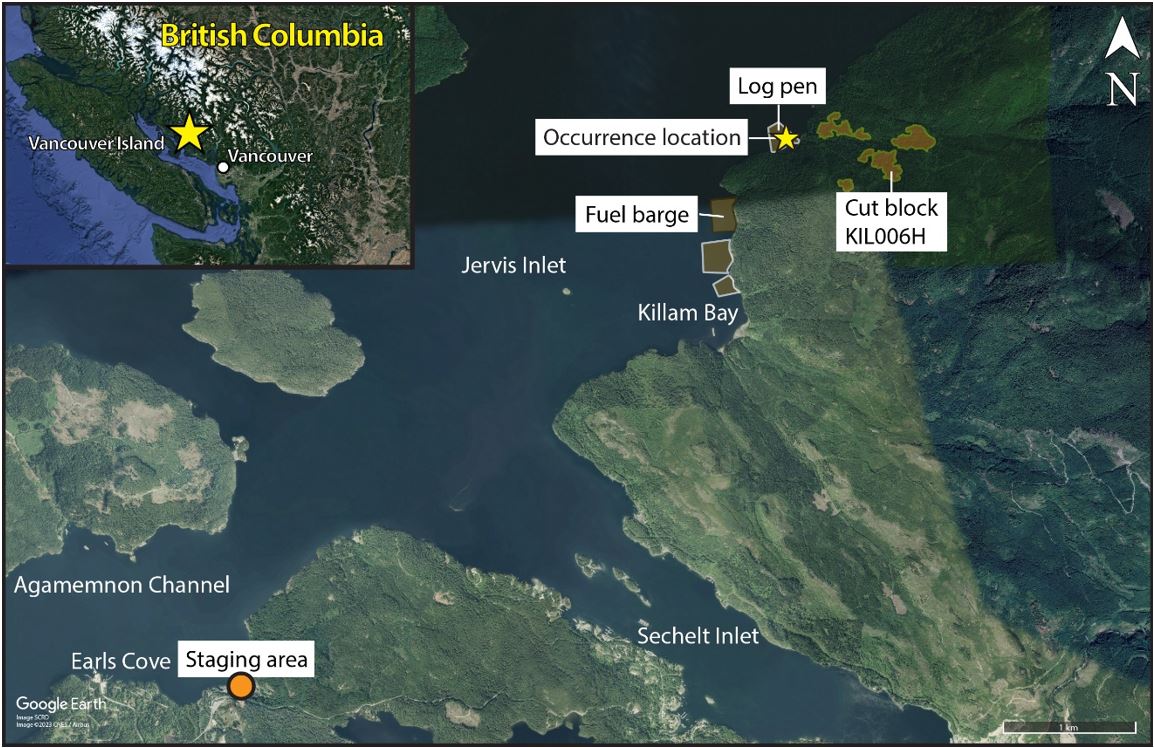
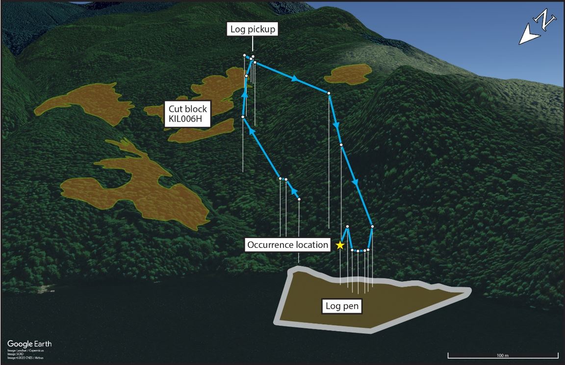
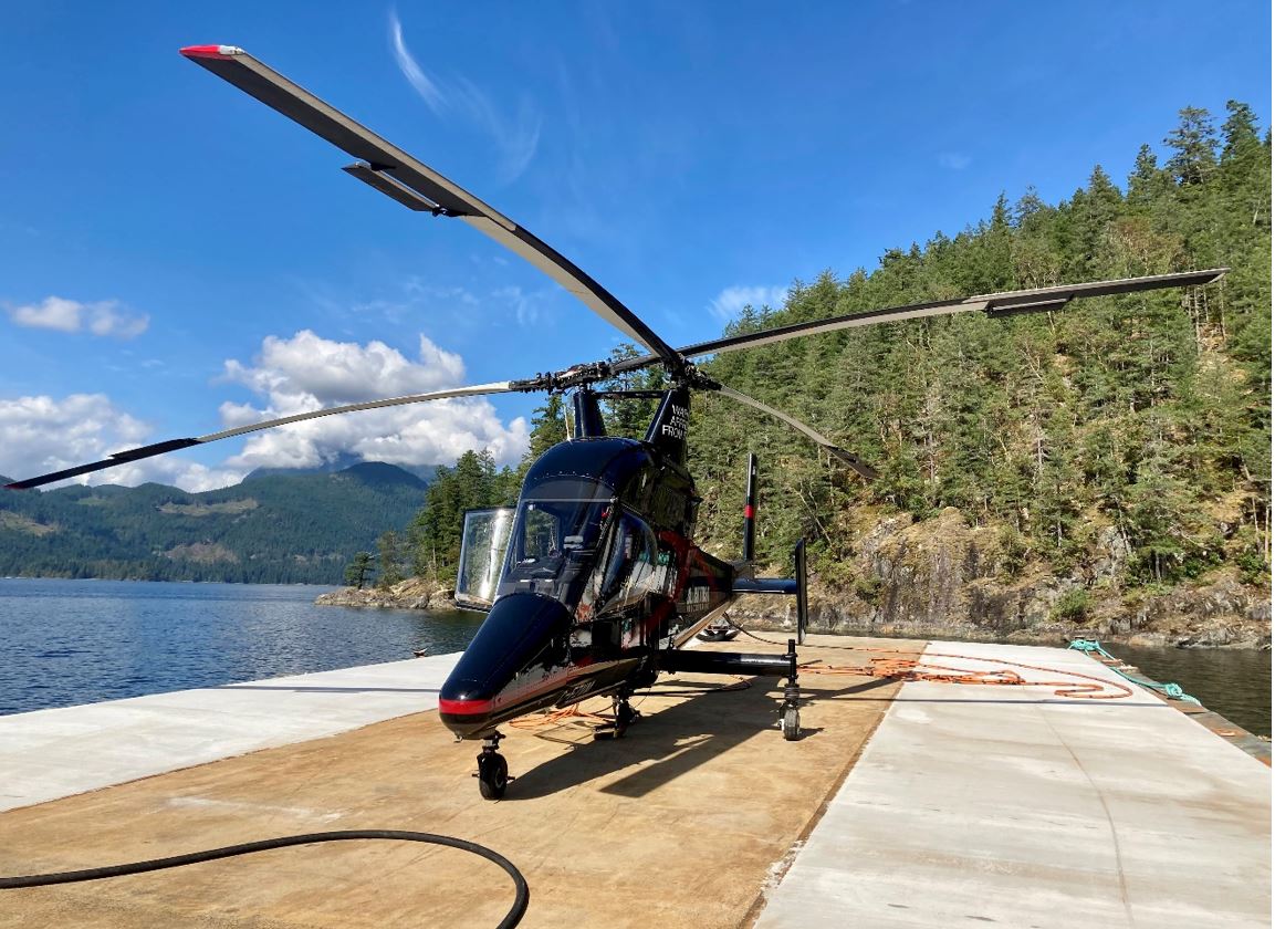
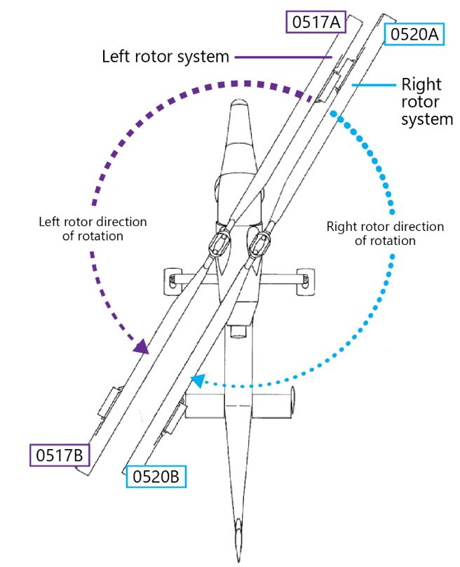
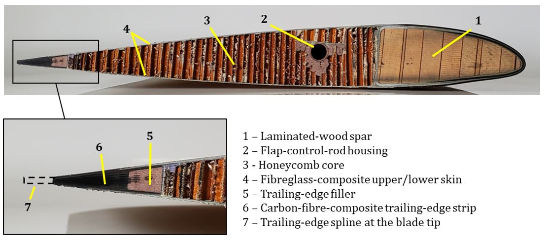

![Figure 7. Servo flap installation on the main rotor blade showing the flap brackets with a diagonal strap, the control-rod connection, and the flap rod (Source: Mario Bazzani – heli-archive.ch [with permission], with TSB annotations) Figure 7. Servo flap installation on the main rotor blade showing the flap brackets with a diagonal strap, the control-rod connection, and the flap rod (Source: Mario Bazzani – heli-archive.ch [with permission], with TSB annotations)](/sites/default/files/2024-10/A21P0107-figure-07-EN.jpg)

