Pipeline rupture and fire
NOVA Gas Transmission Ltd.
36-inch Grande Prairie Mainline
Near Edson, Alberta
The Transportation Safety Board of Canada (TSB) investigated this occurrence for the purpose of advancing transportation safety. It is not the function of the Board to assign fault or determine civil or criminal liability. This report is not created for use in the context of legal, disciplinary or other proceedings. See Ownership and use of content. Masculine pronouns and position titles may be used to signify all genders to comply with the Canadian Transportation Accident Investigation and Safety Board Act (S.C. 1989, c. 3).
Summary
On 16 April 2024, at approximately 1045 Mountain Daylight Time, a 36-inch (914 mm) pipeline owned by NOVA Gas Transmission Ltd. transporting sweet natural gas ruptured about 36.5 km northwest of Edson, Alberta. Following the rupture, the natural gas ignited, resulting in an explosion and fire. Approximately 5 980 000 m3 of natural gas was released. There were no injuries, and no evacuation of members of the public was required.
1.0 Factual information
1.1 The occurrence
On 16 April 2024, at approximately 1045,All times are Mountain Daylight Time. a 36-inch (914 mm) pipeline owned by NOVA Gas Transmission LtdOn 14 May 2024, the entity NOVA Gas Transmission Ltd. (NGTL) was dissolved, and ownership was transferred to NGTL GP Ltd. on behalf of NGTL Limited Partnership. As the occurrence took place before the transition date, NGTL will be used throughout the report. The NGTL system is operated by TransCanada PipeLines Limited (TCPL), referred to herein by the tradename TC Energy. (NGTL)—the NPS [nominal pipe size] 36 Grande Prairie Mainline pipeline (NPS 36 Grande Prairie Mainline)—ruptured at Kilometre Post 36.5. The escaping sweet natural gas ignited and burned until the fire self-extinguished at 1345. The flow of gas to the ruptured section was stopped by closing valves upstream, at the Emerson Creek compressor station, and downstream of the rupture.
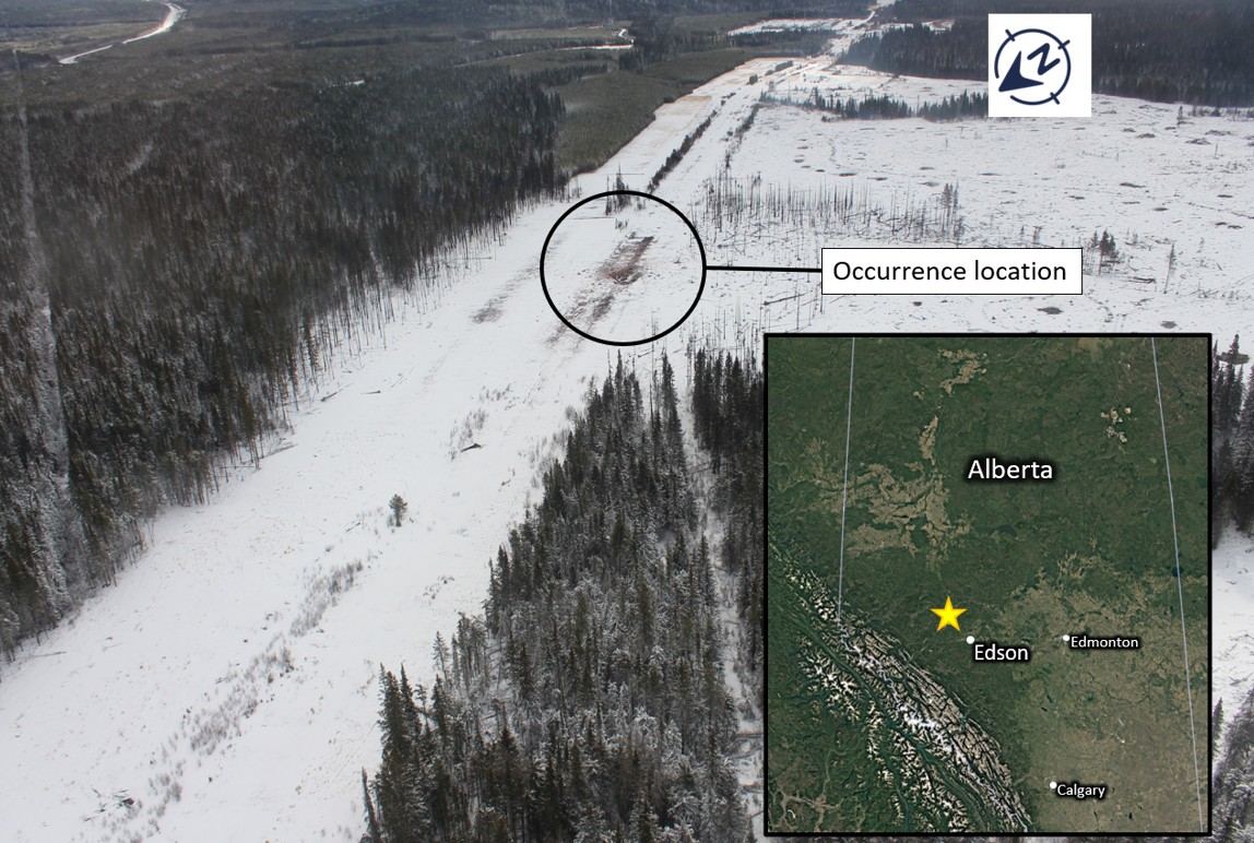
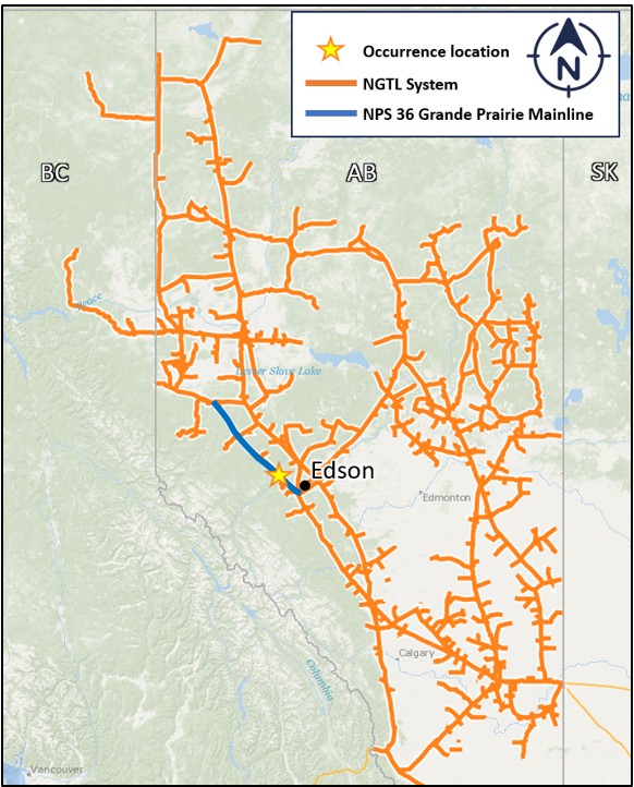
The occurrence took place on a right-of-way used by NGTL (Figure 1). The nearest town to the occurrence site is Edson, Alberta, which is located approximately 36.5 km to the southeast.
In addition to the NPS 36 Grande Prairie Mainline, there are 2 other parallel NGTL pipelines in the right-of-way—a 42-inch pipeline and a 48-inch pipeline delivering natural gas in the same direction. An 8-inch lineThe 8-inch line is owned by Peyto Exploration and Drilling. and a 3-inch lineThe 3-inch line is owned by Secure Energy. owned by third-party companies also run parallel to the NGTL lines.
The occurrence location is surrounded by Crown land for a radius greater than 5 km. There was a work camp building at the Emerson Creek compressor station (located 2.5 km north west of the occurrence site) that had been unoccupied since 01 April 2024 and was in the process of being disassembled at the time of the occurrence. There are no dwellings within a 2 km radius of the occurrence location.
Approximately 5 980 000 m3 of sweet natural gas was released. The resulting wildfire burned a 60.19-hectare area. There were no injuries, and no evacuation of members of the public was required.
At the time of the rupture, the pressure of the NPS 36 Grande Prairie Mainline at the occurrence location was 8110 kPa, within its licensed maximum operating pressure of 8270 kPa. The flow rate was 35 000 000 m3 per day and the gas temperature was 32 °C. The closest upstream compressor station, Emerson Creek, had been put into normal service on 01 April 2024. The station is equipped with 2 compressor units and can deliver pressure and gas flow to the 3 parallel NGTL pipelines operating in the Grande Prairie Mainline right-of-way. The configuration of operating compressor units and flow path is chosen depending on gas demand and other operational considerations. At the time of the occurrence, the compressor station was configured with both compressor units operating and delivering pressure to all 3 NGTL pipelines simultaneously. The ambient temperature was around 2 °C and the wind was from the northwest at 32 km/h.
1.1.1 Sequence of events
On the morning of 16 April 2024, the Emerson Creek compressor station was operating with its 1st compressor unit, A1, active and its 2nd compressor unit, B2, not in use. The Calgary control centre initiated the startup of the B2 compressor unit to increase flow on the NPS 36 Grande Prairie Mainline and the other pipelines in the NGTL right-of-way. It also instructed the on-site operators to open and verify the crossover valves between the NPS 36 Grande Prairie Mainline and the other parallel 42- and 48-inch pipelines. The day of the occurrence was the 1st time that both compressor units were operating in tandem and delivering pressure to all 3 NGTL pipelines in commonIn common mode, all downstream pipelines receive the same compressor station discharge pressure. mode. The timeline for the startup of the B2 compressor unit and the rupture at the occurrence location is detailed in Table 1.
Time | Description | NPS 36 Grande Prairie Mainline pressure* |
|---|---|---|
0809 | Crossover valve to 42-inch pipeline is opened | 7756 kPa |
0940 | B2 unit starts delivering pressure to the pipeline system | 7602 kPa |
1006 | Crossover valve to 48-inch pipeline is opened | 8088 kPa |
1045 | NPS 36 Grande Prairie Mainline rupture | 8110 kPa |
* The NPS 36 Grande Prairie Mainline pressure was measured at the Emerson Creek compressor station.
1.1.2 Occurrence notification and response
The Calgary control centre was actively monitoring the pressures of the NPS 36 Grande Prairie Mainline pipeline and the Emerson Creek compressor station due to the startup of the B2 compressor unit. The on-duty gas controller at the Calgary control centre, through the Supervisory Control and Data Acquisition system, monitored the gradual increase of the Emerson Creek compressor station discharge pressure and, at 1048, noticed that the pressure was dropping. At 1050, an operator at the compressor station called the Calgary control centre to report an explosion and fire and indicated that they suspected that the NPS 36 Grande Prairie Mainline had ruptured. After receiving this call, the TC Energy gas controller decided to shut down and isolate the suspected ruptured section of the pipeline.
An 800 m emergency planning zone was established by TC Energy around the occurrence location to limit access to the occurrence site. At the time of the occurrence, 21 TC Energy and contractor personnel, the only people within this zone, were evacuated.
1.1.2.1 Pipeline isolation
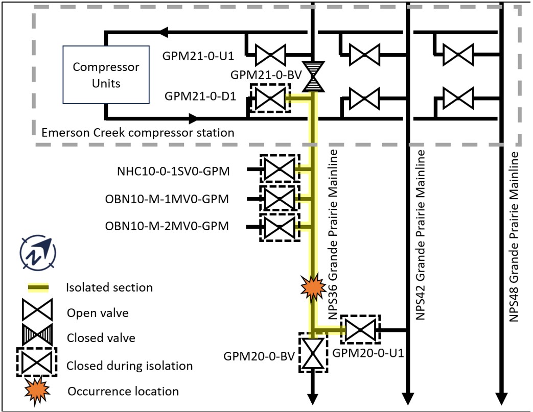
Following the decision to shut down the pipeline, staff at the compressor station initiated the closure of the valve upstream of the rupture location. Technicians were dispatched to downstream valves to complete the isolation of the ruptured section of the pipeline. The pipeline isolation sequence of events is presented in Table 2. A schematic of the isolation is presented in Figure 2.
Time | Description |
|---|---|
1045 (approximately) | The NPS 36 Grande Prairie Mainline ruptures at Kilometre Post 36.5 |
1048 | The controller at the Calgary control centre notices that the Emerson Creek compressor station discharge pressure is dropping |
1050 | A TC Energy operator at the Emerson Creek compressor station phones the Calgary control centre to report an explosion and a fire near the station |
1052 | All compressor units at the Emerson Creek compressor station are shut down |
1059 | Valve GPM21-0-D1 upstream of the rupture location is closed |
1106 | Technicians are dispatched to downstream valve locations |
1114 | Valves OBN10-M-2MVO-GPM and OBN10-M-1MVO-GPM are confirmed to be closed |
1221 | Valve GPM21-0-BV is confirmed to be closed |
1224 | Valves GPM20-0-BV and GPM20-0-U1 are closed |
1236 | Valve NHC10-0-1SVO-GPM is closed* |
1345 | The pipeline fire self-extinguishes |
* The customer upstream of this valve was already isolated from the NPS 36 Grande Prairie Mainline at the time of the occurrence.
1.1.3 Return to service
The ruptured section of the pipeline was replaced on 15 May 2024 and the NPS 36 Grande Prairie Mainline was returned to service under a reduced operating pressureInspection Officer Order JB-001-2024, issued by the Canada Energy Regulator, directed that the NPS 36 Grande Prairie Mainline operate at a pressure not above 80% of the 60-day high pressure before the incident, or 80% of the maximum operating pressure, whichever is lower. on 27 May 2024.
1.2 Site examination
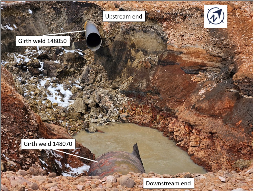
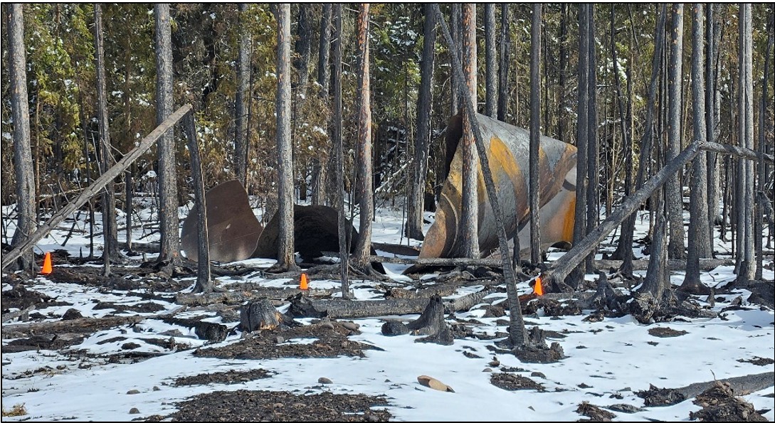
The rupture and explosion created a 7 m-deep crater approximately 40 m by 20 m (Figure 3). The occurrence area is on a gradual southeastern slope on a grassy right-of-way surrounded by coniferous forest. The surface soil is mineral/organic with mineral subsoil consisting of fine and coarse particle size. The material from within the crater consisted of small pebbles and rocks ranging in diameter from 1 to 5 cm, boulders, clay, and shale rock from depths below 5 m.
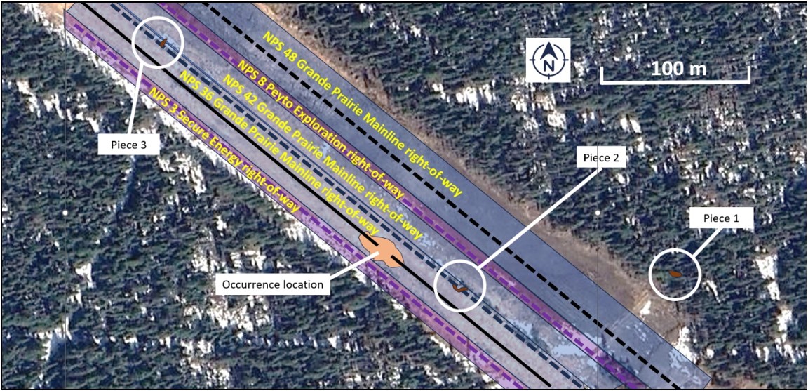
The NPS 36 Grande Prairie Mainline was exposed at both the upstream and downstream ends of the ruptured section. Three large pipe piecesThe pieces were identified as Piece 1, Piece 2, and Piece 3. that were ejected during the rupture were located in the vicinity of the crater (Figure 4). All of the ejected pipeline material, approximately 20 m, was recovered. The largest piece, which included the rupture origin, was located 200 m east of the occurrence location (Figure 5). No damage to other nearby NGTL or third-party infrastructure was reported.
1.3 NPS 36 Grande Prairie Mainline
The NPS 36 Grande Prairie Mainline is part of the NGTL system, a natural gas gathering and transportation system in Alberta and northeastern British Columbia. The NGTL system collects and transports natural gas produced in the Western Canadian Sedimentary Basin to markets in Canada and the United States. The NGTL system has approximately 25 400 km of operating pipelines with about 1100 receipt points and over 300 delivery points.
1.3.1 Description of the pipeline
The NPS 36 Grande Prairie Mainline originates at the Gold Creek compressor stationThe Gold Creek compressor station is at valve site GPM80. and terminates at the Edson meter station,The Edson meter station is at valve site GPM10. for a total length of 205 km (Figure 6). There are 4 compressor stations along the pipeline route: Gold Creek, Latornell, Berland River, and the newly commissioned Emerson Creek, which is located 2.5 km upstream of the occurrence location. There were no pressure restrictions imposed by the Canada Energy Regulator (CER) or the operator on the pipeline at the time of the occurrence.
1.3.2 Pipeline construction
Construction of the NPS 36 Grande Prairie Mainline was completed on 06 May 1981. It was designed and constructed in accordance with the applicable provisions of Canadian Standards Association (CSA) Z184 and has the following specifications:
- maximum operating pressure: 8270 kPa
- class location: Class 1
- type: double-submerged arc-welded longitudinal-seam pipe
- nominal wall thickness: 9.79 mm
- steel grade: CSA Z245.2-M1979 GR.483
- specified minimum yield strength: 483 MPa
The external coating was polyethylene tape coating, which was machine-applied during construction.
Before being put in service, the NPS 36 Grande Prairie Mainline was subjected to a 24-hour hydrostatic test to a pressure of 10 343 kPa. No hydrostatic test failures were reported.
1.3.3 Emerson Creek compressor station
On 01 April 2024, the Emerson Creek compressor station was commissioned and started operation. This station was designed to raise the pressure downstream for the purpose of increasing the throughput of the pipeline system. An assessment of the impacts of this station on the downstream pipelines was conducted in 2021 by TC Energy. At the time of the assessment, the established operating pressureThe established operating pressure is the pressure to which a segment of pipeline is typically exposed. for the pipe downstream of the proposed station was 7808 kPa. The assessment indicated that the predicted maximum expected operating pressure was 8270 kPa, which is the licensed maximum operating pressure for this pipeline. The assessment took into account the effects of increased pressure and temperature and determined that there was no additional risk to the NPS 36 Grande Prairie Mainline downstream of the station.
1.3.4 Cathodic protection system
The NPS 36 Grande Prairie Mainline is cathodically protected by an impressed current cathodic protection (CP) system. The system includes 104 monitoring points and has 2 influencing anode ground beds along the Grande Prairie Mainline right-of-way.The anode ground beds are located at Berland River and Edson. The CP system is surveyed annually to monitor performance.
The 2022 CP survey showed no CP deficiencies in the vicinity of the occurrence.
The 2023 CP survey showed a reading less electronegative than TC Energy’s criteria at a test post 1.77 km away from the occurrence location.The reading was less negative than -850mV recorded at Test Station 1120400+038.428-TS. An electrical bond was installed in early 2024 at the test post where the sub-criteria measurement was found during the survey, which remediated the CP level.
1.4 Laboratory examination
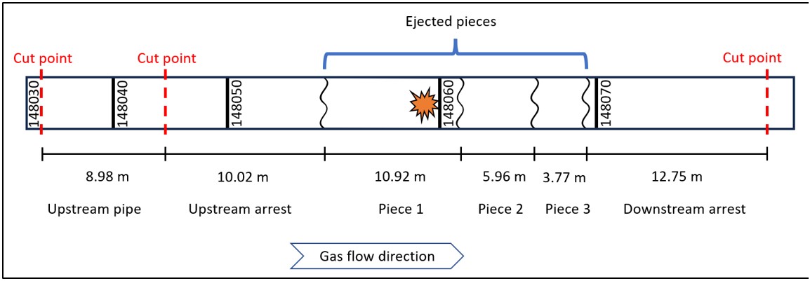
Three ejected pipe pieces were secured on site at the occurrence location. Sections of pipe, including where the fracture stopped propagating, were excavated and cut out. The recovered pipe material was from pipe jointsA pipe joint is a section of pipe between two girth welds. Joints on the NPS 36 Grande Prairie Mainline are identified by the upstream girth weld number. 148030 to 148070 (Figure 7). The ejected pieces, cut-out pipe sections, and soil samples were sent to Acuren Laboratories in Edmonton, Alberta, to determine the mechanical properties of the pipeline and its mode of failure.
1.4.1 Materials testing
The chemical composition and tensile properties of undeformed pipe sections met the requirements of CSA Z245.2-M1979 and CSA Z245.1-2022 for Grade 483 as specified.
The diameterThe specified outside pipe diameter of the pipe was 914.4 mm (36 inches). of the undeformed pipe sections examined were all found to meet the requirements of both the CSA Z245.2-M1979 standard that was in effect at the time of pipe manufacture and the current CSA Z245.1-2022 standard. Wall thickness measurements on all pipe sections also met the specified requirements,The specified nominal wall thickness was 9.79 mm. including at the rupture location, where it measured 10.08 mm.
1.4.2 Cracking and corrosion
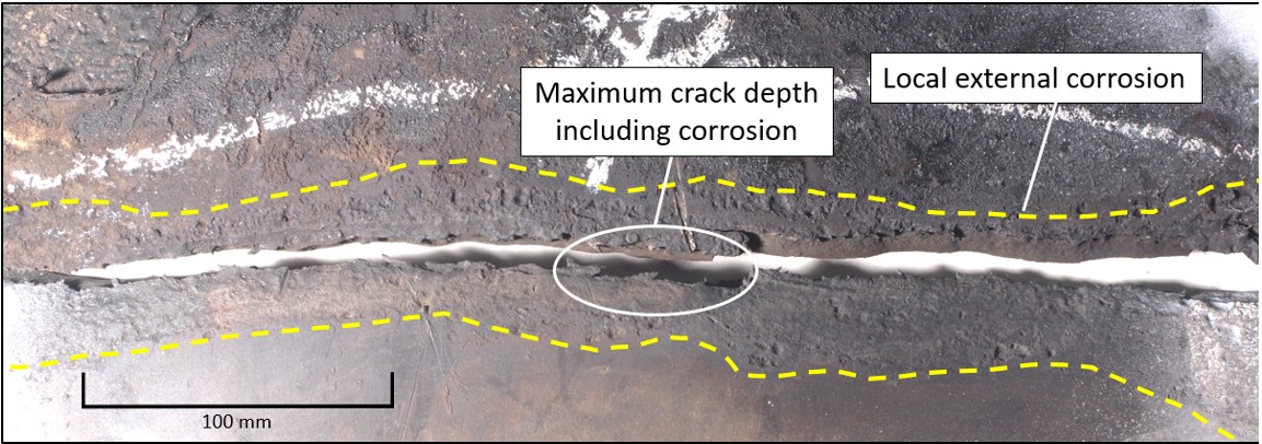
The examined pipe components revealed the presence of general corrosion and stress corrosion cracking. The laboratory analysis determined the failure of the NPS 36 Grande Prairie Mainline to be the result of axially oriented near-neutral pH stress corrosion cracking. The crack at the rupture location was between 8.96 m and 9.33 m downstream of girth weld 148050. All other fractures were ductile fractures resulting from the force of the pipe rupture. External corrosion was present in the local area around the rupture location (Figure 8).
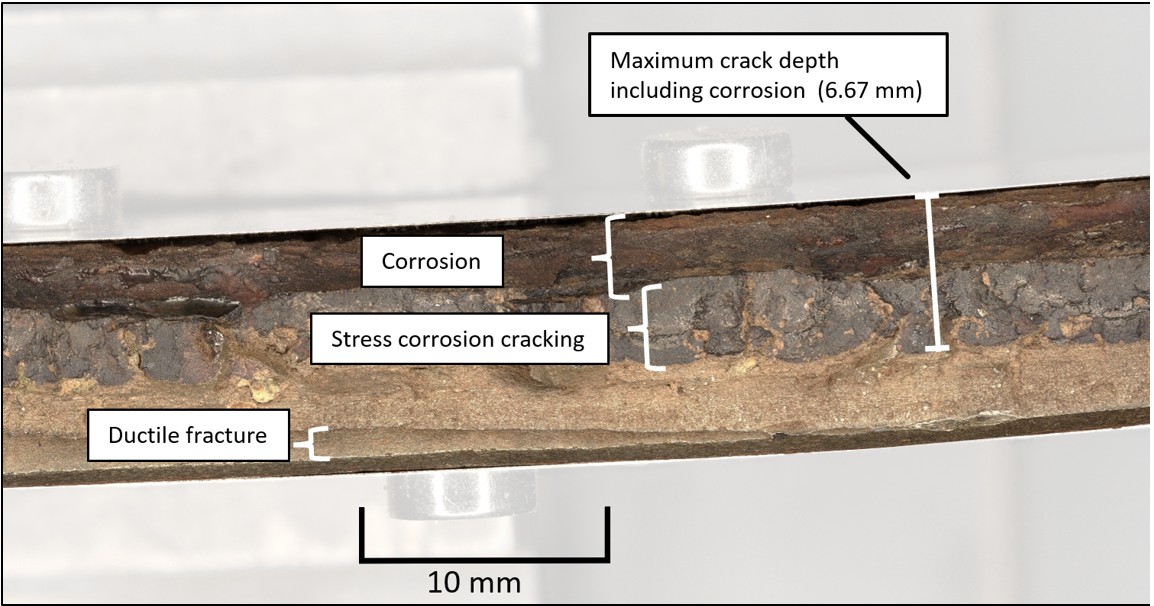
The maximum crack depth, including corrosion,All crack depth measurements include the corrosion. at the rupture location was 6.67 mm, or 67% of the pipe wall thickness (Figure 9).In the vicinity of the deepest crack, the average estimated wall thickness was 10.08 mm. The next deepest cracks on joint 148050 were found to be at maximum depths of 3.86 mm and 2.02 mm, respectively. Cracks on joint 148070 had maximum depths from 1.03 mm to 1.25 mm; otherwise all other measured crack depths were less than 1.00 mm.
The external corrosion tended to be relatively shallow. The deepest corrosion was found on Piece 1. The maximum pit depth was found to be 3.51 mm along the rupture surface; this depth was directly associated with the crack at the rupture location. A few isolated areas within the corrosion adjacent to the rupture location were over 3 mm deep.
1.4.3 Pipe coating
The pipe coating was analyzedThe analysis was performed using Fourier transform infrared spectroscopy. and determined to be high-density polyethylene tape coating. The double-layer tape coating was initially bonded with polyisobutylene and silicate minerals. The tape coating was assessed with the use of 3-dimensional laser scanning. The pipe was scanned with the remaining tape coating still in place, followed by a scan with the disbonded tape removed. A final scan was conducted after the pipe was sandblasted to remove all remaining tape coating and reveal the corroded pipe surface. An example coating assessment scan is presented in Figure 10. Where tape remained on the recovered pipe sections, a considerable area was found to be disbonded. Corrosion, where present, tended to follow areas of coating disbondment and tape wrap lines.
1.4.4 Soil testing
Soil samples were collected from the site and analyzed. The soil resistivity was measured to be between 7580 and 23 300 Ohm-cm and had an average pH of 6.85.
Bacterial analysis was also performed on soil samples. The results determined that both the types of microbes present and the amount detected constituted a relatively high risk for microbial-induced corrosion.Microbial-induced corrosion refers to the deterioration of metallic materials that is accelerated or modified by the presence of microorganisms.
1.5 Near-neutral pH stress corrosion cracking
Near-neutral pH stress corrosion cracking (SCC) on pipelines occurs as a result of the combination of a susceptible metallic material, a suitable environment, and propagates under applied or residual tensile stress, such as hoop stress. This mechanism initiates on the external surface of susceptible pipe and can grow in both depth and length (circumferentially or longitudinally).
The type and condition of the external coating are critical factors in the initiation of near-neutral pH SCC on the exterior surface of pipelines. Polyethylene tape coating was widely used in the 1960s and 1970s on new pipeline construction. This type of coating has a tendency to disbond from the pipeline. The period of time between the installation of the pipeline and the disbondment of the tape coating varies widely and is difficult to determine accurately. The tape coating may disbond soon after construction if it is not applied correctly, or years later due to soil or environmental conditions.
The failure of the tape coating will allow the exterior environment—including groundwater, which has a near-neutral pH—to come in contact with the pipe surface while shielding it from the CP current. SCC may then randomly initiate. Once initiated, some of the SCC will continue to grow as a consequence of the near-neutral pH environment and mechanical forces, such as hoop stressThese stresses are exerted by the pressurized medium contained within the pipe. in a pipe, and it may form colonies of cracks. Colonies of cracks that are long in the longitudinal direction and narrow in the circumferential direction have the potential to coalesce, which accelerates the SCC growth rate and increases the potential of a rupture.
In the 28 years since the National Energy Board’sOn 28 August 2019, the National Energy Board became the Canada Energy Regulator (CER). The National Energy Board will be used throughout the report when pertaining to activities carried out before the transition date. Public Inquiry Concerning Stress Corrosion Cracking on Canadian Oil and Gas PipelinesNational Energy Board, Public Inquiry Concerning Stress Corrosion Cracking on Canadian Oil and Gas Pipelines: report of the inquiry, MH-2-95, 1996, available at https://publications.gc.ca/collections/Collection/NE23-58-1996E.pdf (last accessed 22 September 2025). and its attendant recommendations, many measures have been put in place by the pipeline industry and regulators to help address SCC. These measures included developing and publishing industry-recommended practices and updating federal regulations and pipeline standards. New requirements to develop and implement management systems and integrity management programs were also put in place. This resulted in improvements to the management of SCC by Canadian pipeline operators.
Pipeline operators manage the risks due to the presence of SCC through an SCC management program, which requires a systematic approach to managing pipeline sections that have identified near-neutral pH SCC as a hazard. This type of program uses specific knowledge of the pipelines (design, construction, operation, and inspection history) and applies best practices from across the industry.
1.6 In-line inspection
In-line inspection (ILI) is a non-destructive examination using tools that travel through the pipeline to determine the condition of the pipe. These tools are equipped with sensors that detect cracks, flaws, corrosion, coating disbondment, or geometry anomalies. The data are recorded and analyzed to identify features of interest. After pipe features of interest are identified, pipeline operators can plan to address these features, which can include repairs or pipe replacement.
Typically, pipelines are designed with launching and receiving infrastructure to facilitate the use of ILI tools. For natural gas pipeline integrity management, the most commonly used tool types are electromagnetic acoustic transducer (EMAT), which targets the detection of cracking, and magnetic flux leakage (MFL), which targets metal loss anomalies like corrosion.
1.6.1 Electromagnetic acoustic transducer in-line inspection technology
When an EMAT ILI is performed, an ultrasonic signal is induced in the pipe wall electromagnetically and detected by the tool. Unlike traditional ultrasonic piezoelectric transducers, an EMAT does not rely on the transduction of ultrasonic waves from the sensor to the pipe through a liquid couplant. Because no liquid couplant is required, EMAT tools are ideal for inspecting gas pipelines.
Pipe wall features such as cracks and corrosion will result in reflections of the induced ultrasonic signal. These reflections will be detected by a receiver sensor and recorded. The signal’s characteristics and its time of acquisition, when combined with that of other sensors, provide information about a given feature’s type, size, depth, and location. A typical inspection generates hundreds of thousands of reflection signals, with only a small number of these being reportable features.
1.6.2 Probability of detection and identification
Cracks and other features of interest detected by ILI tools are not measured directly but rather interpreted from sensor signals. The industry reference document for qualifying a tool’s ability to detect defects and to quantify the uncertainty of an ILI tool measurement is American Petroleum Institute standard API 1163.American Petroleum Institute (API), API Standard 1163, In-line Inspection Systems Qualification (3rd Edition, September 2021).
The probability that a given inspection tool will detect a feature of interest, the probability of detection (POD), is based on the physical capabilities of the tool and the size of the defect. The standard requires that the performance specifications clearly state detection thresholds and PODs.
The probability that a sensor signal will be correctly identified as a specific feature type is known as the probability of identification (POI). An ILI tool performance specification must clearly state a statistically derived POI. Similarly, an inspection tool must state a statistically derived sizing accuracy.
With criteria defined by the pipeline operator, these probabilities and crack sizing accuracy are combined to give the total probability that features of interest will be reported; this is called the probability of reporting (POR) (Figure 11).
1.6.3 In-line inspection tool used on the NPS 36 Grande Prairie Mainline
The NPS 36 Grande Prairie Mainline is fitted with launching and receiving facilities to allow the use of ILI tools to clean and inspect the pipeline. All previous EMAT inspections on the NPS 36 Grande Prairie Mainline were conducted by a third-party, Baker Hughes. Baker Hughes is a global pipeline service provider that has inspected thousands of kilometres of pipeline in Canada with its EMAT ILI tools in the last 10 years. The ILI tool used by Baker Hughes is the EMATScanCD ILI tool.
Baker Hughes’ EMAT technology was initially developed between 2007 and 2010. The development and refinement of the tool hardware, software, and analysis procedures used full-scale testing with artificial features created to demonstrate the viability of the technology. The EMATScanCD tool inspection specifications for POD, POI, and feature sizing were built on this foundational work.
Since 2010, continuous performance monitoring of the EMATScanCD tool, including POD, POI, and sizing predictions, has been occurring as the tool is used in the field. Operators provide the results of integrity excavations to verify the features as found in the field. Cut-out sections of pipeline with known features have also been provided to Baker Hughes by pipeline operators to further refine the tool’s algorithms and to update classification guidelines. POD and POI are derived following API 1163 using a dataset that includes artificial and as found features.
Selected specifications for the EMATScanCD tool are presented in Table 3.
Specification* | Value |
|---|---|
Minimum crack depth | 2 mm |
Minimum crack length | 50 mm |
Probability of detection (at minimum length and depth) | 90% |
Probability of identification | 80% |
Depth sizing accuracy | +/- 1.1 mm at 80% certainty +/- 1.5 mm at 90% certainty |
* The specification assesses items at a 95% confidence level.
1.6.4 Data analysis process
After EMAT ILI field inspection activities, a data quality check is performed to verify that sensors are functioning and that the dataset is complete. Once this check is completed, an initial automated process identifies signal patterns in the data that may indicate a feature of interest.Features of interest are classified by Baker Hughes as “Crack-like,” “Crack Colony,” and “Weld Anomaly.” Non-reportable feature types include “Metal Loss,” “Inclusion,” and “Fitting,” among others. This automated process results in a large number of these indications, which are each referenced to the axial and circumferential measurements of the pipe.
After the automated process is completed, a team of data analysts, each of whom works independently, analyzes signal patterns to determine if any of the indications represents a feature of interest. Each analyst reviews thousands of indications with the aid of classification guidelines developed by Baker Hughes. Quality control of this work is performed by more senior analysts. The majority of indications in an inspection represent non-injurious features, material inclusions, and welded fittings, which are all filtered out at this stage. Signal patterns that are found to indicate potential cracks are assigned an estimated size and included in a list for further analysis by a review committee.
The review committee is composed of 4 senior analysts who independently review the list of potential cracks. Review committee membership is not fixed and is organized for each project. At a review committee meeting, each feature is discussed and a decision is made as to which cracks will be included in the final report to the customer and which ones will be downgraded to a non-reportable feature type. Depending on the project, there will be either 1 or 2 rounds of review committee meetings. The decision to downgrade a feature needs to be unanimous; if any one analyst believes the feature is a crack meeting the reporting threshold,The reporting threshold of a feature of interest is a pre-defined minimum size beyond which the feature will be reported. it will be included in the final report.
While the final decisions of the review committee meetings are recorded, the content of discussions and rationale for decisions are not systematically captured in review committee documentation, nor are they shared with the customer. At the conclusion of review committee meetings, features that do not meet the reporting threshold or are downgraded to a non-reportable type are removed from the final list. Only reportable feature types and cracks that meet the reporting threshold are included in the report.
Features reported on previous inspections of the same pipeline are reviewed to compare them to the current inspection. Similarly, new reportable features in the most recent inspection are reviewed against the historic inspection data. This information is presented in tabular format in the inspection report delivered to the customer. Aside from the comparison to previously reported features, no information about non-reportable feature types or cracks that do not exceed the reporting threshold is included in the inspection report.
The use of previous inspection data as part of the routine data analysis is not systematic and is only used on an ad hoc basis when an analyst requires more context. Historic data are generally not consulted in order to avoid biasing the analyst while identifying and classifying crack-like features.
1.6.5 In-line inspection history
Since its original construction, the NPS 36 Grande Prairie Mainline had been inspected multiple times using various types and generations of ILI technologies starting with magnetic flux leakage tools in 1997. The pipe was first inspected for cracks using an EMAT tool in 2013 and was subsequently inspected in 2018 and 2022.
The crack at the rupture location was detected in previous ILIs of the pipeline (Table 4). However, it was not reportableFollowing the established process, features below the reporting threshold are not reported to the end users. in any of the reports provided to TC Energy.
Inspection run | Classification | Feature depth | Notes |
|---|---|---|---|
2013 EMAT | “Crack field” | 1-2 mm | Below reporting threshold |
2018 EMAT | “Crack field” | 1-2 mm | Below reporting threshold |
1.6.6 2022 in-line inspection
The most recent EMAT inspection commenced on 13 October 2022 and the final report was issued to TC Energy on 12 January 2023. Of the total 205 km length of the NPS 36 Grande Prairie Mainline, 191 km of pipeline were inspected.The pipeline sections that were not inspected had a heavier wall thickness, which was outside the specifications of the EMATScanCD tool. All sensors on the EMATScanCD tool functioned correctly and no issues were reported with data quality. There were 9 total features reported to TC Energy.
A summary of the analysis process is presented in Table 5.
Process step | Number of indications |
|---|---|
Automated feature detection | Over 2 million |
Committee review* | Over 600 |
Reported to TC Energy | 9 |
* Includes features from 2 separate review committees.
During the automatic stage of the data analysis, a signal pattern indicating a potential feature of interest was detected at the location of the feature that failed in this occurrence.It was identified as feature set 337-007945. The analyst review included the feature as a potential crack. During quality control, the feature was classified as a “crack field” with an estimated depth of 3.2 mm. The feature was then included in a list of features to be reviewed by the review committee.
1.6.6.1 Review committee
The feature was discussed by a 4-person review committee as part of Baker Hughes’ analysis process. As part of their independent reviews ahead of the meeting, 3 of the 4 analysts elected to downgrade the feature. During discussion, the review committee ultimately decided to downgrade the feature from a reportable “crack field” type to a non-reportable “metal loss” feature classification. As part of this decision-making process, the feature was not compared against the indications observed in the 2018 or 2013 inspections, and there was no requirement to do so. The decision of the review committee to downgrade the feature was unanimous after discussion. However, the rationale for this decision was not documented. Baker Hughes conducted a post-accident review of the signal data and indicated that the feature should have been classified as a “crack colony.” With a “crack colony” classification, the feature that ruptured would have been reported as a crack with an estimated depth of 3.4 mm.
1.6.7 In-line inspection tool data analyst training and experience
The training and certification of Baker Hughes’ ILI personnel involve formal classroom training, on-the-job training, and certification examinations.
Baker Hughes has a written practice for ILI inspection personnel, per the provisions of the ANSI/ASNT ILI-PQThe American Society for Nondestructive Testing, Inc., In-Line Inspection Personnel Qualification and Certification (2017). standard applicable to ILI personnel in the pipeline industry. This written practice outlines requirements for field operators and data analysts for certification levels I, II, and III. These levels relate to the level of experience, seniority, and responsibility expected for the role. Personnel must re-certify every 3 years through training and testing, including for the same qualification level.
The initial analysis of crack-like indications is conducted by level I and II analysts, with quality control being conducted by level II or III analysts. Review committees are composed of the most senior, level III, analysts.
1.7 Variability of human performance
Variability is an inherent part of every aspect of human functioning, from the molecular level to complex sociotechnical systems.T. J. Smith, R. A. Henning, M. G. Wade, and T. Fisher, Variability in Human Performance (United States: CRC Press), 2014, p. xiii-5. When discussing the variability of human performance, the concept can be understood in 2 different ways:
- “Differences in individual or system performance at any given point in time”Ibid, p. xiii.
- “Changes across time in performance within or between individuals or systems”Ibid.
Across a variety of domains, criteria, and categories, human performance exists along a distribution of possible outcomes, any of which may manifest depending on the variables present that interact to influence a person's performance.
While human performance variability has historically been viewed negatively and as a cause of accidents, more recently, it is better understood as an asset as it enables us to manage complex work systems that are unable to be described in detail and require day-to-day adaptation on the part of human operators.E. Hollnagel, Safety-I and Safety-II: The Past and Future of Safety Management (United States: CRC Press), 2014, pp. 44-45 and 118-122. Regardless of how it is viewed, human performance variability is an element of system performance that must be recognized and accounted for in terms of risk management as it can affect operations in a variety of ways.
1.8 Regulatory requirements for integrity management
The Canadian Energy Regulator Onshore Pipeline Regulations (the Regulations) require a company to establish, implement, and maintain a management system and various protection programs, including an integrity management program (IMP). The Regulations further require pipeline operators, through incorporation by reference, to adhere to applicable mandatory provisions of the latest edition of CSA Z662,Canadian Standards Association, CSA Z662: Oil and gas pipeline systems (2023). which provides the minimum requirements related to a pipeline’s design, construction, operation, maintenance, deactivation, and abandonment.
While the CER, in its Guidance Notes for the Canadian Energy Regulator Onshore Pipeline Regulations,Canada Energy Regulator, Guidance Notes for the Canadian Energy Regulator Onshore Pipeline Regulations (2013), available at https://www.cer-rec.gc.ca/en/about/acts-regulations/cer-act-regulations-guidance-notes-related-documents/onshore-pipeline/guidance-notes-for-the-canada-energy-regulator-onshore-pipeline-regulations.html (last accessed 23 September 2025). provides direction in developing an IMP, regulated companies have flexibility and discretion to develop the content of their plans. In general, regulated companies develop IMPs tailored to their specific operations and take corrective actions as required, in compliance with applicable provisions and criteria set out in CSA Z662.
The CER expects companies, as part of their IMPs, to proactively identify and continually monitor the specific hazards associated with their pipelines and associated facilities, and to update their programs immediately when new hazards are identified.
CER-regulated companies are held accountable to operate safely during all phases of a pipeline life cycle. The CER monitors the effectiveness of each company’s program on an ongoing basis using audits and compliance verification activities to ensure that pipelines and associated facilities are suitable for continued safe, reliable, and environmentally responsible service.
The CER does not regulate ILI service providers but does keep up to date with the most recent progress made in the industry. The CER regularly meets with pipeline operators in annual information exchange venues that include discussions about ILI technology and its role within pipeline operator IMPs.
1.8.1 Stress corrosion cracking management best practices
The industry-recommended practices for managing near-neutral pH SCC are contained within CSA SPE 225.7Canadian Standards Association, Managing near-neutral pH stress corrosion cracking (2022). This document was originally developed by the Pipeline Integrity Working Group under the auspices of the Canadian Energy Pipeline Association (CEPA), a voluntary, non-profit industry association that was representing major Canadian transmission pipeline companies. The ownership of this document was transferred to the CSA Group in November 2021, shortly before CEPA ceased its operations. and API RP 1176.American Petroleum Institute (API), Recommended Practice 1176: Assessment and Management of Cracking in Pipelines (2016). The basic components for near-neutral pH SCC management are as follows:
- Susceptibility assessment – the assessment of a pipeline segment based on attributes such as age, diameter, coating type, operating pressure, and soil type.
- Investigation to detect the presence of SCC
- Characterization and mitigation of SCC – if an investigation reveals SCC, the severity of the SCC is classified to enable decisions to be made regarding suitable crack mitigation, and determination of reassessment interval.
- Document, learn, and report – documenting decision processes used in evaluating susceptibility and effectiveness of mitigation activities.
- Condition monitoring – monitoring the condition of the pipeline for changes that might affect the SCC susceptibility.
1.9 Pipeline integrity management program
TC Energy’s IMP is guided by a risk assessment developed by TC Energy, the System Wide Risk Assessment (SWRA). The SWRA creates a digital twin of TC Energy’s pipeline network. The digital twin is segmented into smaller sectionsSections average 70 m in length, with a maximum of 200 m. that are analyzed individually.
Risk is a function of the probability of a pipeline failureThe type of failure that predominantly influences risk levels in the model is a pipeline rupture. and the consequences of the failure. The SWRA model contains 2 criteria for risk: individual risk (IR) and societal risk (SR). The individual risk criterion is intended to protect individuals that may live, work, or be occasionally present near the pipeline.Canadian Standards Association, CSA Z662: Oil and gas pipeline systems (2023), Annex B, Clause B.6.1.2.1, states “The broadly acceptable individual risk threshold is 1×10⁻⁶/year and the maximum tolerable risk threshold is 1×10⁻⁴/year.” The societal risk criterion is intended to protect populations along the pipeline from occurrences that can involve multiple casualties.Ibid., Clause B.6.1.2.2: Societal risk. CSA Z662, Annex BIbid., Annex B., provides guidelines for quantitative risk assessment of natural gas pipelines.
Threats listed in The American Society of Mechanical Engineers (ASME) standard B31.8S,The American Society of Mechanical Engineers, B31.8S: Managing System Integrity of Gas Pipelines (2022). along with additional threats identified by TC Energy,External corrosion, internal corrosion, stress corrosion cracking, circumferential stress corrosion cracking, seam weld manufacturing defect, hard spot, first and second party external interference, third party external interference, construction defects, deformation, weather outside forces, equipment malfunction and incorrect operations, and thermal expansion. are considered in the SWRA. Threats such as external corrosion and SCC can interact with one another and these interactions are also considered.
The total risk results are compared against the criteria for both IR and SR. If either of the total risk criteria are exceeded, the largest contributing threats are addressed as part TC Energy’s IMP, resulting in threat-specific preventive, assessment, control, or mitigations. Data from integrity activities to assess the state of the pipeline network are used as inputs into the SWRA.
Threats can be time-dependent, such as external corrosion, static, or resident threats like manufacturing-related defects, or time-independent such as external interference. Each threat is managed by a threat management team.
Cracks reported by ILI and from integrity excavations are also fed into the SWRA process to determine the risk of failure. An SWRA is performed on each segment to calculate the total risk for all threats.
1.9.1 TC Energy requirements for in-line inspection technologies
TC Energy has requirements for ILI technologies. For EMAT inspections, the requirements state that inspection tools shall detect, identify, and size cracks with a minimum of 90% POD and 80% POI for features meeting the minimum tool length and depth tolerance specifications.
For cracks deeper than 5 mm or more than 50% of the pipe wall thickness in depth,This requirement applies to cracks with a minimum length of 75 mm for 36-inch pipelines. TC Energy requires that inspection tools detect and identify these cracks 100% of the time in alignment with the ILI performance specification.
1.9.2 Cracking threat management
As per TC Energy’s IMP, SCC is reviewed annually during TC Energy’s SWRA cycle. This process combines all knowledge and information available at the time of the assessment. The SWRA addresses all threats, which include SCC, and establishes assessment priorities as part of TC Energy’s IMP.
TC Energy has criteria to determine if a pipeline segment is susceptible to SCC. Examples of criteria used to determine susceptibility include the age of the pipe, coating type, operating pressure, and whether SCC has been discovered in the past.
The NPS 36 Grande Prairie Mainline meets TC Energy’s SCC susceptibility criteria due to
- possible coating disbondment due to low-performance coating;
- more than 10 years since construction;
- previous SCC findings on this pipeline;
- operating pressure greater than 60% specified minimum yield strength (SMYS).
EMAT ILI is TC Energy’s primary assessment method for identifying crack threats on TC Energy pipelines, including on the NPS 36 Grande Prairie Mainline. TC Energy uses 2 ILI service providers to conduct these inspections: either Baker Hughes or Rosen is selected for a particular run based on tool availability and operational considerations. All reported features from either service provider are delivered in a standard format and assessed by TC Energy following its procedure for the analysis of EMAT ILIs.
All reported cracks are evaluated to identify features that require immediate action. Cracks reported to TC Energy after an ILI are evaluated as immediately actionable if they show cracking with a depth of more than 50% of the pipe wall thickness or predicted failure pressures below acceptable safety factor thresholds. Immediate action can include a self-imposed pressure restriction and/or an integrity management project to excavate the crack location and perform repairs if necessary. In the evaluation process, the reported cracks are sized accounting for the tool tolerance. A growth rate is applied to all reported cracks to determine when action is required and when a pipeline segment will be scheduled for re-inspection. The results of the crack evaluation are also an input to the SWRA. The risk model assumes the presence of undetected cracks based on the segment’s SCC susceptibility. The undetected cracks are assumed to be the maximum undetected crack size at the EMAT tool’s specified reporting thresholds. For segments of pipeline that do not have a current ILI, these undetected cracks are continually grown until a new inspection is completed. For the NPS 36 Grande Prairie Mainline, TC Energy uses a crack growth rate of 0.3 mm/year and the next inspection was scheduled for 2025.Seven years is the maximum re-inspection interval for re-inspections according to TC Energy Engineering Procedures TEP-IN-EMAT-G Analysis of EMAT In-line Inspection Data for CDN Pipelines (CDN).
As part of the management of SCC, TC Energy conducts integrity excavations in response to ILI findings along with opportunistic inspections when pipeline segments are excavated for other purposes.
Since 2013, EMAT ILIs of the NPS 36 Grande Prairie Mainline have prompted TC Energy to conduct 32 integrity excavations. All features excavated were found to be either within tool tolerances or oversized.Oversized indicates that the tool predicted the crack would be bigger than its real size. TC Energy provides EMAT ILI providers with results from integrity excavation activities for the purpose of continuous improvement of the EMAT technology, including tool data analysis algorithms and procedures.
1.9.2.1 Cracking within corrosion
SCC is a threat that TC Energy recognizes as one that can interact with external corrosion. In 2017, TC Energy and Baker Hughes completed a study on crack sizing for cracks that occur within corrosion. The study found that the Baker Hughes EMAT tool was able to predict absolute crack depths when the crack was coincident with external corrosion. The dataset of 169 features showed that crack size and depth predictions performed better than the stated tool specifications.
1.9.3 Previous stress corrosion cracking failures on TC Energy pipelines
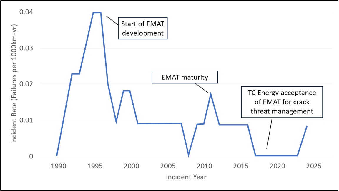
SCC failures on TC Energy’s pipelines prompted inquiries by the National Energy Board in 1993 and 1995. These inquiries contributed to the understanding of SCC and how to manage its effects. Since that time, EMAT technology has matured to become the primary tool for TC Energy and the rest of the pipeline industry to manage SCC. The frequency of SCC failures has declined since the adoption of this technology. After a validation period, TC Energy accepted the use of EMAT ILI in 2018 as the primary tool for the management of SCC. This occurrence is the first instance of a rupture on a TC Energy pipeline that has been inspected by an EMAT tool (Figure 12).
1.10 TSB laboratory reports
The TSB completed the following laboratory report in support of this investigation:
- LP122/2024 – Failure Analysis of Natural Gas Pipeline Rupture and Fire (Review of Acuren Laboratory Report)
2.0 Analysis
The analysis will focus on the condition of the pipe with an increased operating pressure, the identification of cracks as part of the in-line inspection data analysis process, crack evaluation, and the risk assessment used for managing the threat of stress corrosion cracking. The incident response was conducted in a timely manner and was not considered contributory to the consequences of the accident.
2.1 The occurrence
On 16 April 2024, the NPS [nominal pipe size] 36 Grande Prairie Mainline pipeline (NPS 36 Grande Prairie Mainline) ruptured at Kilometre Post 36.5, which is approximately 2.5 km downstream of the Emerson Creek compressor station. That morning, the B2 compressor unit was started and configured to deliver pressure to the pipeline system in tandem with the A1 unit, which was already running.
Before the commissioning of the Emerson Creek compressor station on 01 April 2024, the pipeline at the occurrence location was historically subjected to an average operating pressure of around 7808 kPa. The new compressor station was designed and installed to boost the pipeline’s pressure, increasing the flow of gas through the NPS 36 Grand Prairie Mainline and the 2 parallel NOVA Gas Transmission Ltd. (NGTL) pipelines. The pressure downstream of the station was expected to reach the pipeline’s maximum operating pressure of 8270 kPa.
At 0940 on the day of the occurrence, with both compressor units operating, the pipeline pressure was increased to 8110 kPa; the rupture occurred approximately 5 minutes later. While the planned pressure increase was within the allowable operating limit of 8270 kPa for this pipeline, the failure pressure was the highest operating pressure that the occurrence location had experienced since the pipeline had been constructed. Before the commissioning of the compressor station, an assessment conducted by TC Energy determined that an increase in pressure did not pose a risk to the integrity of the pipeline.
2.2 Near-neutral pH stress corrosion cracking
Near-neutral pH stress corrosion cracking (SCC) on pipelines is a result of the combination of a susceptible metallic material, an applied or residual tensile stress, and a suitable environment. It takes place on the external surface of susceptible pipe and can grow in both depth and length.
The crack at the rupture origin was determined, through laboratory analysis, to be the result of near-neutral pH SCC occurring within a groove of external corrosion. The maximum crack depth, including corrosion, was measured to be 6.67 mm, or 67% of the wall thickness. The total length of the feature was approximately 370 mm.
Laboratory examination of the failed pipe section also found that the external polyethylene tape coating on the NPS 36 Grande Prairie Mainline in the vicinity of the occurrence location had degraded and that corrosion was present where the coating had disbonded from the pipe surface. When polyethylene tape coating disbonds from the pipe surface, it can locally reduce the effectiveness of the pipeline’s cathodic protection system. Testing of the soil showed microbiological activity with the potential to corrode the pipeline steel. With the external coating compromised, the pipeline steel was exposed to the external environment where corrosion could occur.
Findings as to causes and contributing factors
The operating pressure of the NPS 36 Grande Prairie Mainline increased to a point at which an existing crack failed. As a result, the pipeline ruptured and an explosion and fire ensued.
The soil conditions and the pipeline’s disbonded coating, which exposed its steel surface, and its internal gas pressure initiated near-neutral pH SCC at the rupture location.
2.3 In-line inspection
The NPS 36 Grande Prairie Mainline had been inspected with an electromagnetic acoustic transducer (EMAT) tool multiple times since being put into service, as part of TC Energy’s integrity management program to manage the threat of cracking. The most recent EMAT inspection, conducted in 2022 by Baker Hughes, reported 9 features exceeding the criteria of 2 mm in depth and 50 mm in length. The crack that failed at the rupture origin was not included in the report for this inspection.
The analysis process at Baker Hughes uses trained and experienced analysts that follow classification guidelines to interpret the signal patterns generated from an in-line inspection (ILI) and determine their meaning. The classification guidelines are qualitative in nature and the analysis process relies on human interpretation to identify if a signal pattern represents a crack or a different type of anomaly.
The signal pattern generated by the feature at the rupture origin was detected during the automated data process stage and included in a list of indications for further processing. At that stage, an analyst initially identified the feature as a crack, prompting it to be included in a list of features for further consideration by a review committee. Each of the 4 senior analysts on the review committee examined every identified feature on this list independently according to their own interpretation of the classification guidelines. The committee then met and discussed each feature to determine whether it should be included in the final report to the pipeline operator.
At the review committee meeting, the feature at the rupture origin was discussed. Three of the 4 senior analysts had initially determined that the feature was not a crack. After discussion, the review committee unanimously determined that this feature should be downgraded to a non-reportable “metal loss” classification. The inspection data for the previous ILI conducted in 2013 and 2018 were not consulted as part of the discussions leading to the downgrade. The final decision of the review committee was recorded, but the rationale for coming to this decision was not recorded as part of the analysis process.
Finding as to causes and contributing factors
The feature at the origin of the rupture, which was caused by SCC and detected by an ILI conducted in 2022, was classified as non-reportable by the inspection service provider. As a result, it was not included in TC Energy’s ILI analysis process or risk assessment for the NPS 36 Grande Prairie Mainline.
2.4 Human performance variability in data analysis
TC Energy has used Baker Hughes’ EMAT inspections for many pipelines within its network. TC Energy provides Baker Hughes with reports from excavated features to help further refine its technology and processes. Compiled data from pipelines inspected by Baker Hughes for TC Energy show that the EMAT tool performance consistently exceeds the service provider’s specifications for the detection and sizing of cracks. The EMAT technology is physically capable of detecting cracks, including those that occur within corrosion such as the one that failed in this occurrence.
While EMAT technology has become invaluable as a tool for pipeline integrity management, the inspection process still relies quite heavily on human interpretation of the large volumes of data being generated to identify features that meet the threshold for reporting to customers. These interpretations are based on evaluation criteria that are qualitative in nature, meaning that they provide ranges and describe general characteristics of features but are not able to provide a clear answer for every case. Despite the work being conducted by experienced personnel who have been trained and certified in accordance with industry best practices, these qualitative assessments are subjected to the natural human performance variability inherent in how humans perform most tasks.
This risk presented by human performance variability is mitigated by the multiple layers of quality control and review for EMAT data, including a review committee composed of 4 senior analysts. During a committee review, any 1 of the 4 analysts on the committee can elect to include a feature in a final report; consensus is not required.
Since this Baker Hughes inspection process has been in place, this occurrence represents the only case where a misidentified feature from an EMAT inspection led to a pipeline failure, an indicator that Baker Hughes’ inspection process is reliable.
In this occurrence, the review committee unanimously determined that the signal pattern corresponding to the feature at the rupture location did not indicate a crack and downgraded the feature to a non-reportable type. Despite the reliability of EMAT ILI for detecting cracks, the variability of human performance introduces the possibility that a crack will go unreported on any given inspection.
Finding as to risk
The variability of human performance in the analysis of EMAT ILI data introduces the possibility that a pipeline crack is not identified, resulting in a missed opportunity to manage it.
2.5 Risk-based pipeline integrity management
TC Energy’s integrity management program is guided by a System Wide Risk Assessment (SWRA), which estimates the individual or societal risk from all threats for any given location in its pipeline network. If any risk is determined to exceed an acceptable level, the largest contributing threats are addressed with preventive, assessment, control, or mitigation actions.
TC Energy utilizes EMAT ILIs to manage the threat of SCC. On an ongoing basis, TC Energy provides inspection service providers with information about crack sizes as found in the field to improve the capabilities of the tools and the associated data analysis. Based on TC Energy’s excavation data, EMAT tools have consistently exceeded their stated accuracy specifications for sizing cracks, and since 2018, TC Energy has used this type of inspection as the primary method for managing SCC on its pipelines. Despite the continual improvements of the technology, pipeline operators are aware that the probability of detection, identification, sizing, and reporting of cracks from an EMAT inspection is subject to uncertainties inherent to the capabilities of the tool and the analysis of inspection data.
EMAT ILI reports produced by service providers are presented as a list of features that exceed an established reporting threshold. However, through analyzing the EMAT data to produce these reports, inspection service providers also have a large amount of information about features that do not meet the reporting threshold or are otherwise determined to be not reportable. This type of information is generally not included in the reports provided to pipeline operators.
The list of features and their locations on the pipeline included in the inspection reports provide information to pipeline operators to direct their integrity management activities in the field. For the purposes of the SWRA, the calculation of the probability of failure due to SCC depends on whether a pipe segment has reported cracks from an ILI. If the pipe segment has reported cracks, the probability of failure is the combined probability of failure of all the cracks on that segment. Since ILI inspection reports do not typically provide information about features determined not to be reportable, the risk model assumes the presence of undetected cracks based only on the segment’s SCC susceptibility. Without any specific information about their locations and characteristics, uncertainties related to the possible presence of unreported features in any given segment are not accurately captured by the SWRA. Consequently, the SWRA may not accurately evaluate the possibility of unreported features being present or their likelihood of failure in any given pipe segment.
Finding as to risk
If a pipeline risk assessment does not include information about the locations and characteristics of unreported features from in-line inspections, the calculated probabilities of failure for the pipe segment being assessed may not accurately reflect the condition of the pipe.
3.0 Findings
3.1 Findings as to causes and contributing factors
These are factors that were found to have caused or contributed to this occurrence.
- The operating pressure of the NPS [nominal pipe size] 36 Grande Prairie Mainline pipeline increased to a point at which an existing crack failed. As a result, the pipeline ruptured and an explosion and fire ensued.
- The soil conditions and the pipeline’s disbonded coating, which exposed its steel surface, and its internal gas pressure initiated near-neutral pH stress corrosion cracking at the rupture location.
- The feature at the origin of the rupture, which was caused by stress corrosion cracking and detected by an in-line inspection conducted in 2022, was classified as non-reportable by the inspection service provider. As a result, it was not included in TC Energy’s in-line inspection analysis process or risk assessment for the NPS [nominal pipe size] 36 Grande Prairie Mainline pipeline.
3.2 Findings as to risk
These are factors in the occurrence that were found to pose a risk to the transportation system. These factors may or may not have been causal or contributing to the occurrence but could pose a risk in the future.
- The variability of human performance in the analysis of electromagnetic acoustic transducer in-line inspection data introduces the possibility that a pipeline crack is not identified, resulting in a missed opportunity to manage it.
- If a pipeline risk assessment does not include information about the locations and characteristics of unreported features from in-line inspections, the calculated probabilities of failure for the pipe segment being assessed may not accurately reflect the condition of the pipe.
4.0 Safety action
4.1 Safety action taken
4.1.1 TC Energy
In response to the occurrence, TC Energy applied pressure restrictions on the NPS [nominal pipe size] 36 Grande Prairie Mainline pipeline (NPS 36 Grande Prairie Mainline) in compliance with the Canada Energy Regulator’s direction in Inspection Officer Order JB-001-2024. An engineering assessment was completed for the return to service of the pipeline section between valves GPM21 and GPM20, at a reduced operating pressure.
In May 2024, an integrity excavation was completed for the adjacent NPS 42 Grande Prairie Mainline Loop pipeline near the occurrence location to verify the absence of external pipe coating damage. The inspection was completed, confirming no impact to the coating of the adjacent pipeline.
In June 2024, an electromagnetic acoustic transducer (EMAT) inspection was completed on the NPS 36 Grande Prairie Mainline with an alternative in-line inspection (ILI) vendor’s EMAT tool. A circumferential magnetic flux leakage (MFL) inspection was also completed. In response to the 2024 ILI inspections, integrity excavations were initiated on the NPS 36 Grande Prairie Mainline as per TC Energy’s stress corrosion cracking (SCC) management procedures.
4.1.2 Baker Hughes
Baker Hughes conducted an internal investigation and provided results to TC Energy and the TSB.
Baker Hughes contacted pipeline operators within Canada and outside Canada that may have been affected to share and implement any learnings from the NPS 36 Grande Prairie Mainline occurrence.
Baker Hughes also implemented process steps for the mandatory recording of downgrade decision rationale at committee review in the EMAT data analysis steps within the EMAT project Quality Management System documentation for any modifications of feature classification.
4.1.3 Canada Energy Regulator
On 06 May 2024, the Canada Energy Regulator (CER) issued Inspection Officer OrderInspection Officer Orders issued by the CER can be amended or rescinded based on the progress of actions taken by the pipeline operator. JB-001-2024 to the NOVA Gas Transmission Ltd. (NGTL) Accountable Officer directing NGTL to not operate the NPS 36 Grande Prairie Mainline segments at a pressure above 80% of the respective segment 60-day high pressure before the occurrence, or 80% of the maximum operating pressure, whichever is lower.
The CER conducted the inspection of an integrity excavation to verify adherence of the company’s procedures to the requirements of the Canadian Energy Regulator Onshore Pipeline Regulations and of the Canadian Standards Association’s CSA Z662: Oil and gas pipeline systems standard.
This report concludes the Transportation Safety Board of Canada’s investigation into this occurrence. The Board authorized the release of this report on 27 August 2025. It was officially released on 09 October 2025.

![Figure 11. Example of an in-line inspection system demonstrating relationship of probability of detection, probability of identification, and sizing accuracy with probability of reporting (Source: adapted from American Petroleum Institute’s API Standard 1163 [2021], Annex G, Figure G.1) Figure 11. Example of an in-line inspection system demonstrating relationship of probability of detection, probability of identification, and sizing accuracy with probability of reporting (Source: adapted from American Petroleum Institute’s API Standard 1163 [2021], Annex G, Figure G.1)](/sites/default/files/2025-10/P24H0018-figure-11-ENG.jpg)
