Natural gas pipeline rupture
TransCanada PipeLine Limited
Line 100-1, 762-Millimetre-Diameter Pipeline
Main Line Valve 111A-1, from kilometres 11.12 to 11.16
Near Marten River, Ontario
The Transportation Safety Board of Canada (TSB) investigated this occurrence for the purpose of advancing transportation safety. It is not the function of the Board to assign fault or determine civil or criminal liability. This report is not created for use in the context of legal, disciplinary or other proceedings. See Ownership and use of content. Masculine pronouns and position titles may be used to signify all genders to comply with the Canadian Transportation Accident Investigation and Safety Board Act (S.C. 1989, c. 3).
Summary
At approximately 1144 Eastern daylight time on 26 September 2009, TransCanada's Line 100-1 ruptured near Marten River, Ontario. At 1151, Gas Control at TransCanada's Calgary office became aware of this event when Main Line Valve 112-1, on the upstream side of Compressor Station 112, automatically shut off due to low pipeline pressure. At the time of the occurrence, TransCanada was transporting sweet natural gas. The escaping gas did not ignite. A large crater was created and pipe pieces were ejected from the failed pipeline section and spread around the occurrence site. There were no injuries.
Factual information
The accident
Prior to the occurrence, the pipeline system had been operating normally under ordinary conditions. The operating pressure and temperature at this location were estimated to be 5228 kPa (approximately 750 pounds per square inch) and 12.5°C. For the TransCanada PipeLine Limited (TransCanada) Line 100-1, between Compressor Station 110 and Compressor Station 112, the maximum allowable operating pressure (MAOP), as approved by the National Energy Board (NEB), is 6895 kPa.
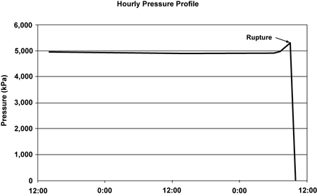
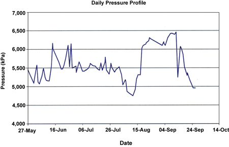
In the vicinity of the occurrence, there are three parallel pipelines buried approximately 0.914 meters (m) below ground, spaced approximately 20 m and 43 m apart. Just before the occurrence, the flow rate in Line 100-1 between Compressor Station 110 and Compressor Station 112 was 7 100 000 cubic metres per day (m³/day), or approximately 252 million cubic feet per day. The Supervisory Control and Data Acquisition (SCADA) operating data indicates that the rupture occurred at approximately 1144Footnote 1 (see Figure 1). The volume of natural gas lost during the occurrence is estimated to be 1 430 000 cubic metres (or 50 750 000 cubic feet).
At 1147, SCADA telemetry indicated abnormal and falling pipeline pressures upstream of Compressor Station 112, with an associated low pressure alarm in Calgary Gas Control (Gas Control) on Line 100-1. At 1151, TransCanada's Main Line Valve (MLV) 112-1, located upstream of Compressor Station 112, closed automatically as its low pressure shut-off was triggered. This MLV is a 30-inch diameter full opening ball valve that can be operated automatically from the station control room, remotely by Gas Control, or locally by hand, if required. When MLVs are equipped with an automatic low pressure shut-off control sensing (LPSOCS) system, the valve will automatically close when a low pressure situation is detected in the pipeline. Using the SCADA telemetry system, the Gas Control operator (the operator) verified that there had been a pipeline break on Line 100-1 in Northern Ontario.
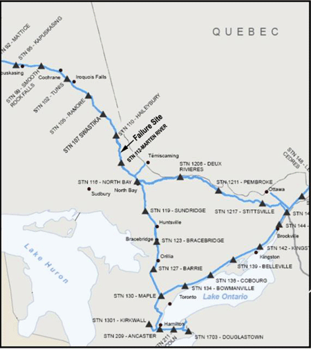
Shortly thereafter, Gas Control received telephone notification from the Ontario Provincial Police on its Emergency Hot-Line that a pipeline failure had occurred approximately 700 metres upstream of Compressor Station 112, located near Marten River, Ontario (see Figure 2).
At 1200, the SCADA telemetry indicated that MLV 111A-1, immediately upstream of the occurrence site, also closed automatically after its low pressure shut-off had been triggered. This MLV is a 30-inch diameter full opening ball valve that is also equipped with the LPSOCS system. As a result of these automatic MLV closures, the flow of natural gas on Line 100-1 was stopped between the compressor stations 110 and 112.
On 12 September 2009, TransCanada had had a pipeline failure on Line 100-2 at Englehart, Ontario (TSB Report Number P09H0073), which is located upstream of the present occurrence site. As a safety precaution, the adjacent section of Line 100-3 had been taken out of service until the integrity of the pipe surface, which had been exposed by the Line 100-2 failure, could be confirmed. At approximately 0945, on 26 September 2009, the adjacent section of Line 100-3, between MLV 107 to MLV 108, was being returned to normal pipeline service. During the pipeline repairs of Line 100-2, this section of lines 100-2 and 100-3 had been isolated from normal pipeline operations; the remainder of lines 100-2 and 100-3 stayed open for natural gas movements; and the operating pressures in lines 100-1, 100-2 and 100-3 had decreased below maximum operating pressure (MOP) in the course of normal operational conditions. With Line 100-3 back in service on 26 September 2009, the return from decreased operating pressures to normal operations resulted in an increase in pipeline pressures across the entire system downstream of the Englehart Compressor Station, at the time of the Line 100-1 failure. During this period of time, the pressure on all three pipelines was below MOP, the result of flow demand on the operating system.
The nearest home to the rupture site is located approximately 1.6 km to the southeast. The nearest town to the occurrence site is Temagami, Ontario with a population of approximately 1000 residents, located approximately 30 km north of the incident site. The nearest roadway is located approximately 0.3 km to the east. Highway 11 is located approximately 1 km east of the incident site.
On the day of the occurrence it was raining with a light wind and the temperature was 24°C.
Actions by gas control operator
After receiving the alarm notification of an event on the system, the operator initiated the established procedure for verifying pipeline breaks. Review of the SCADA telemetry confirmed that there had been an abnormal pressure drop on Line 100-1 between compressor stations 110 and 112.
The operator then initiated the remote command feature "ISOLATE ALL" via the SCADA system to Station 112, and did the same for Station 110 a moment later. The SCADA telemetry confirmed the isolation of MLVs between compressor stations 110 and 112 for lines 100-1, 100-2, and 100-3 (see Figure 3). These pipelines were also isolated from each other as the tie-over valves between the pipelines closed (the tie-over valves allow for the movement of natural gas between the pipelines when required). Gas Control then dispatched regional personnel to isolate all the lines in the area of the occurrence.
Site examination
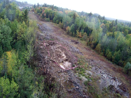
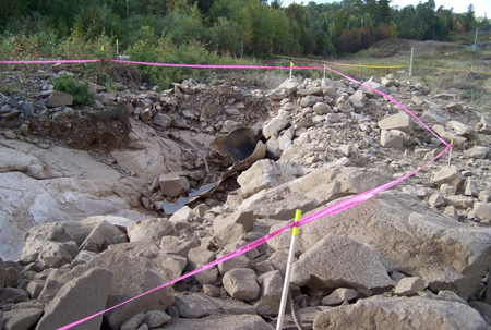
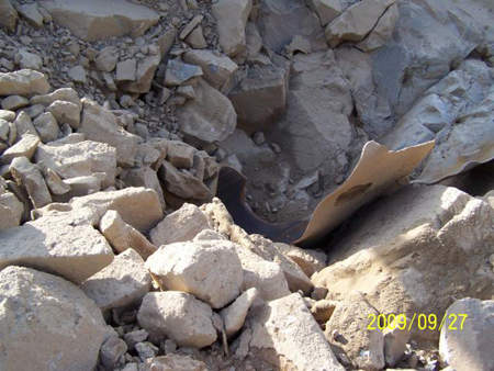
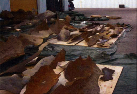
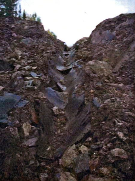
During the rupture, a section of pipe separated from the pipeline and was scattered throughout the area in more than 40 pieces of varying sizes (see Photo 1). The upstream and downstream joints of the pipe were severely damaged (see Photos 2 and 3). Pieces of pipe were found up to approximately 100 m away from the site of the rupture.
The upstream and downstream fracture arrests were cut off the ends of the pipe and retained for further examination. More than 40 pieces of pipe were also collected (see Photo 4).
Site clean-up and pipeline restoration
The failure on Line 100-1 occurred in an area of bedrock within MLV-111A section. This pipeline was covered with a sand pad protection onto which a bedrock of fractured granite had been laid. The granite cover was blasted out at the time of construction in the late 1950s and was subsequently reused to bury the pipeline. The local area is characterized by a series of undulating depressions that are mostly poorly drained organics over bedrock and upland bedrock areas.
The failure site was located on a high spot of undulating land that was well drained and surrounded on both sides by boreal forest. The TransCanada pipeline easement is located on Crown Land. During the rupture, a portion of a cathodic protection groundbed and the power distribution system for the cathodic protection system were damaged.
Numerous pieces of pipe were ejected onto the pipeline right of way and into the adjacent forested area. Figure 4 identifies the locations where pipe pieces were found.
Lines 100-2 and 100-3 were not affected by the pipeline rupture and were quickly returned to normal service, but at a reduced operating pressure. However, the valve section between MLV 111A-1 and MLV 112-1 on Line 100-1 remained locked-in, with no natural gas movements in the MLV section, until the repairs were complete. The remainder of Line 100-1 stayed in service at a reduced operating pressure.
The explosion exposed 37.7 m of pipeline, and damaged a total of 82.95 m of pipe. The damaged portions of Line 100-1 were replaced with 85 m of pre-tested pipe (i.e., hydrostatically tested and conforming to NEB's authorized pressures). At 1500 on October 30, the pipeline repairs were completed.
At 1630 on November 3, Line 100-1 between MLV 111A-1 and 112-1 was returned to normal service and operated at full line pressure. There were no operational problems encountered on start-up.
After the repairs were done and the line had returned to normal service, the exposed pipeline was backfilled. On November 4, site repairs and restoration work were completed.
TransCanada pipeline system - Overview
With the addition of the Alberta System (previously referred to as Nova Gas Transmission) to federal jurisdiction in April 2009, TransCanada became the largest high/low pressure natural gas delivery system in North America. TransCanada's natural gas system extends from British Columbia to Quebec and consists of more than 39 000 km of buried pipe and 118 compressor stations. The mainline portion of the system is comprised of up to eight pipelines at certain locations and is divided into 30-km intervals (approximately) by isolation valves.
The original Line 100-1 pipe, components and bolting material were manufactured in accordance with the requirements of the American Society of Mechanical Engineers (ASME) B31.8 - 1955 titled "Gas Transmission and Distribution Piping Systems".
Class of pipeline
Most of the TransCanada mainline system was laid in sparsely-populated regions and is classified as Class 1 according to existing industry standards. In more populated areas or where there are other risk factors (e.g., close proximity to schools, hospitals, etc.), heavier wall pipe thicknesses, classified as Class 2, 3 or 4 are installed. A Class 4 location represents an area of heavy urban population.
Line 100-1 had an outside diameter of 762 millimetres (mm) (30 inches), a MAOP of 6895 kPa and the pipe wall thickness was 9.53 mm for this Class 1 location. The pipe thickness is based on a common pipe grade of 359 megaPascals (MPa) (American Petroleum Institute [API] pipe grade X-52). Sections of the Line 100-1 pipe were manufactured in 1958 by A. O. Smith Line Pipe at its Milwaukee, Wisconsin plant and then randomly installed during original construction.
Recorded information
A review of the SCADA trend logs for compressor stations 110 and 112 indicated that, in the 5 months prior to the occurrence, no unusual operating event had taken place in this section of the pipeline (see Figure 5).
Laboratory analysis of the failed pipe
The pieces of failed pipe collected at the rupture site were sent to the Acuren Group Inc. Laboratory (the laboratory) in Edmonton, Alberta, for a series of tests: visual examination, dimensional measurements, non-destructive inspection, and metallurgical testing. The laboratory work determined that:
- The pipe strength in the area of the failed joint met the requirements of the API 5LX-X52 specification in place at the time of installation as well as the current requirements of the CSA Z245.1, Grade 359.
- The pipe had a nominal diameter of 30 inches (762 mm) and a wall thickness of 9.53 mm, with a flash butt weld, typical for pipe manufactured in the 1950s.
- A hard spotFootnote 2 on the pipe surface of one of the pieces was identified as the location of the rupture initiation. The hard spot would have been formed as a result of local quenching of the steel plate, immediately following the final hot rolling pass, and had been present in the steel surface since the time of its manufacturing.
- The toughness of the material was determined through a Charpy impact test of the pipe steel, which is a standardized method to determine the amount of energy absorbed by a material during fracture. The test determined that the pipe toughness near the point of failure was relatively poor (with a hard spot on the pipe surface located at the 5:30 to 6:00 o'clock position) and accounted for the extensive brittle fractures found in the entire pipe joint involved in the rupture.
- The rupture in TransCanada's Line 100-1 was the consequence of a one-time failure event resulting from the combination of a hard spot in the pipe, a tensile stress caused by the internal gas pressure and the probable presence of atomic hydrogen in the steel at the rupture location.
Staff from the Transportation Safety Board (TSB) were present at the laboratory and found the nature of the work performed and methodologies used consistent with good failure analysis practice.
Removal of A.O. Smith pipe due to hard spots
On 08 July 1969, TransCanada experienced a pipeline failure that was attributed to a hard spot in a pipe manufactured by A.O. Smith, situated 9.8 km from the MLV 111A-1. It was determined that hard spots were likely to be found in A.O. Smith pipe as a result of its manufacturing process. TransCanada initiated a pipe integrity program (PIP) to identify and replace A.O. Smith pipe across the pipeline system. TransCanada determined that the A.O. Smith pipe had been placed randomly across the system during its original construction, which complicated the pipe removal and replacement project.
TransCanada was required by the NEB, pursuant to the Order SG-1-78 (the Order) to undertake programs related to the integrity management of hard spots associated with A.O. Smith pipe on this pipeline. Specifically, the Order mandated that TransCanada replace all locations of A.O. Smith pipe on Line 100-1, when encroachment changes occurred in locations near areas of high hazard consequences, such as road crossings, hospitals, and private residences. In 1978, TransCanada began a comprehensive replacement program of A.O. Smith pipe.
Between 1969 and 1999, TransCanada replaced approximately 44 km of the original Line 100-1 due to the presence of hard spots.The replacement pipe met the conditions of the Order. The closest section that had been replaced in accordance with the Order was located at MLV 112, approximately 13.49 km away from the area of this occurrence. The pipe was replaced in 1979.
In the 1990s, in-line inspection (ILI) tools with the capability of detecting and locating hard spots were being developed. Utilizing a High Magnetization In-Line Inspection (HMILI) tool to magnetize the pipe surface, then following with a second ILI tool to record locations where the magnetic charge had not diminished, TransCanada was able to identify with a high degree of accuracy the location of A.O. Smith pipe for removal purposes. In view of the development of those tools, the NEB amended the Order on July 28 2000 with Amended Order AO-1-SG-1-78 (Amended Order).
Since 2000, the pipe replacement program has consisted of utilizing a HMILI tool with a residual magnetic charge detection function to detect hard spots in the pipe.
Due to the risks associated with hard spots, the Order and Amended Order are still in effect. As part of TransCanada's ongoing program, all valve sections, including the vicinity of this occurrence at MLV 111A-1, are monitored on an annual basis for any population density increases near the A.O. Smith pipe to determine whether pipe should be replaced or tested for hard spots. Since the Amended Order has been issued, there had been no pipe replacement or integrity verification issues in the area of this occurrence.
Hydrostatic testing of Line 100-1
When Line 100-1 was originally installed in 1958, the section between MLV 111A-1 and MLV 112-1 was pressure-tested for natural gas in accordance with the requirements of the American Standards Association (ASA) standard titled "Gas Transmission and Distribution Piping Systems ASA B31.8", which was in effect at the time. A test pressure of 7085 kPa was held for 24 hours.
Beginning in 1968, the NEB approved a re-rating program for all of Line 100-1 to permit TransCanada to operate the pipeline system at a higher operating pressure. The re-rating program consisted of, amongst other items, complete hydrostatic testing and repair of all ruptures and leaks. In 1974, during the re-rating test of the occurrence section of pipeline, water was used as the hydrostatic test medium. The test pressure achieved during this 24 hour test qualified the pipeline for a MAOP of 6895 kPa (i.e. minimum test pressure was 1.25 times MAOP).
In-line inspection of Line 100-1 for corrosion
As part of TransCanada's annual Pipeline Maintenance Plan (PMP), TransCanada inspects its pipelines using magnetic flux leakage (MFL) ILI tools. This type of inspection device is designed to identify internal and external metal loss, such as surface corrosion. MFL ILI tools do not measure the depth of the corrosion directly. The operator interprets the electronic signal received from the ILI in order to determine the depth and length of any identified corrosion pit. The interpreted measurement is not very precise. An accurate measurement of any identified corrosion pit can only be made by excavating the pipeline and taking direct surface measurements with a hand-held device or by cutting out a section of the pipeline.
The failed section of Line 100-1 was internally inspected using MFL ILI tools, launched from MLV 110 and received at MLV 116, in 1999 and 2004:
- In 1999, the greatest depth of metal loss recorded was 70% of pipe wall thickness, but the corrosion site was not located in the failed valve section. Near the rupture site, seven post-ILI excavations were conducted that resulted in four cut-outsFootnote 3.
- In 2004, the greatest depth of metal loss recorded was 88% of pipe wall thickness. This reading was not taken in the failed section. A subsequent excavation revealed that the actual depth of metal loss was 59% of pipe wall thickness.
The next MFL inspection was planned for 2010.
In-line inspection of Line 100-1 for hard spots
During the original construction, approximately 385 km of A.O. Smith pipe was installed within 80 valve sections on Line 100-1. At the time of the present occurrence, 38 of those sections had been internally inspected using a HMILI tool with a residual magnetic charge detection function to locate hard spots.
The section of Line 100-1 between MLV 110-1 and MLV 116-1 had been inspected in February 1997 in the course of a trial ILI initiated by TransCanada to help develop a new hard spot detection tool. The inspection was for tool development purposes and was not a result of population encroachment. The only usable data was from MLV 111 to MLV 111A. Three excavations were undertaken as part of the tool validation process but no hard spots were found. From 2000 until the occurrence, no pipe replacements or integrity verifications resulting from the Amended Order were done between MLV 110-1 and 116-1. Following this occurrence, TransCanada made plans to inspect Line 100-1 for hard spots between MLV 61-1 and 75-1 and between MLV 110-1 and 116-1.
Cathodic protection of Line 100-1
Since its initial construction, Line 100-1 has been under continuous cathodic protection (CP), which is measured in millivolts (mV) relative to the copper-copper sulphate reference electrode. In the vicinity of the rupture site, CP potential is provided by two rectifiers:
- The upstream rectifier is located at MLV 111A. This rectifier powers three remote groundbeds and a distributed groundbed within the first 6.43 km of the valve section.
- The downstream rectifier is located at MLV 112. The rectifier powers two distributed ground-beds and two remote ground-beds.
As part of the PMP, pipe-to-soil potentials (PSP) and close interval potential surveys (CIS) are conducted. Prior to the occurrence, the most recent PSP survey had been conducted in April and June of 2009. The respective recorded values were -1028 mV and -1163 mV in the vicinity of the failure. These values conform to TransCanada's standards for CP.
CIS surveys are conducted on an as-required basis to verify and optimize CP system operations. The most recent CIS survey was conducted in 2000 to verify the operation of the CP system following new anode installations in 1999. This CIS survey recorded 'off' potential values of about -1000 mV at all points tested, which conforms to TransCanada's standards for CIS. There were no CP anomalies detected during this survey.
Prior to the occurrence between MLV 111A-1 and 112-1, there were no external coating repairs performed. As well, there was no indication of ground water problems at the occurrence site. After the occurrence, during pipeline repairs, it was observed that rain water was accumulating in the ditch. However, no seepage of water was observed emanating from the ditch walls during the repair work.
The exterior of the pipe at the occurrence site was coated in asphalt enamel. The exterior coating in the area where the pipe failed showed evidence of poor condition and extensive exterior coating disbondment (see Photo 5).
Regulatory requirements regarding pipeline integrity management
Pursuant to section 40 of the NEB's Onshore Pipeline Regulations, 1999 (SOR/99-294) (NEB Regulations), federally regulated pipeline companies are required to develop pipeline integrity management programs. Section 41 of these regulations requires a company which finds a level of defect in excess of that allowed by Canadian Standards Association Z662-07, Oil and gas pipeline systems (CSA Z662-07), to document the particulars of the defect, its likely cause and the corrective action taken or planned. Section 10.2.1 of the CSA Z662-07 requires operating companies to develop, implement, and maintain a documented safety and loss management system for the pipeline system that provides for the protection of people, the environment, and property. Section 10.3.3 of CSA Z662-07 requires that leaks and breaks be investigated to determine their causes, and that measures be taken to prevent the occurrence of leaks or breaks due to similar causes.
TransCanada's integrity management process for pipelines
In response to pipeline failures during the period from 1961 to 1978 associated with hard spots on Line 100-1, TransCanada began planning an intensive field program, which was eventually referred to as the Pipeline Maintenance Program (PMP). Since 2000, this program has consisted of utilizing a HMILI tool with a residual magnetic charge detection function to detect hard spots in the pipe.
A pipeline rupture on Line 100-2 in August 1985 was associated with stress corrosion cracking (SCC). TransCanada began inspecting its pipelines for SCC following this event. In response to the detection of the SCC mechanism in Line 100-1 in Northern Ontario, TransCanada expanded the PMP for Line 100-1 to address this integrity issue. The SCC program included hydrostatic testing of susceptible sections of the system and investigative excavations along the pipeline.
TransCanada's Integrity Management Process for Pipelines (IMPP) is the governing document for integrity management of its pipeline facilities, including Line 100-1. The IMPP uses a risk-based pipeline integrity management process (i.e., System-Wide Risk Assessment (SWRA)) to address safety and service reliability of the pipeline system, as well as to address regulatory requirements and various pipeline standards. The IMPP discusses the safety and service reliability of the pipeline system, as well as the regulatory requirements and other related standards (e.g., Canadian Standards Association pipeline standards).
Within IMPP, as part of Hazard Identification and Risk Assessment, SWRA information is used to develop the annual PMP. While not fully implemented, TransCanada considered its approach to hazard identification and risk management fully compliant with pipeline regulations and equivalent to American Society of Mechanical Engineers Standard (ASME) B31.8S titled "Managing System Integrity of Gas Pipelines", dated 2004. At the time of the occurrence, TransCanada was in the process of implementing this management system governing the delivery of integrity management programs on the pipeline system.
As TransCanada developed its IMPP, the company considered the ASME B31.8S and adopted some of the requirements of that standard. However, since the standard is a non-mandatory consensus standard, TransCanada did not adopt certain requirements it deemed were not appropriate to its pipeline system. For example, there were no changes to TransCanada's IMPP with respect to the use of the HMILI tool in the valve sections downstream of Line 100-1 compressor stations.
Risk assessment results for Line 100-1
In 2009, TransCanada's IMPP identified the following time-dependent threats for Line 100-1:
- external corrosion
- stress corrosion cracking
- steel pipe manufacturing.
TransCanada also identified other general hazards to pipeline facilities, including third-party mechanical damage, incorrect operations and equipment failure. Its Operating and Maintenance Practices and Procedures helps mitigate general threats associated with equipment failures and incorrect operations. Mitigation of third-party mechanical damage is achieved through its Integrated Public Awareness program.
External corrosion for Line 100-1
To mitigate the threat of External Corrosion on Line 100-1, TransCanada conducted a number of defect management condition assessments utilizing an MFL tool. The most recent ILI was conducted in 2004. Between 2004 and 2009, no sites were excavated for corrosion in the section of pipeline from MLV 111A to MLV 112.
After the occurrence, the intact lengths of pipe upstream and downstream of the failed pipe were inspected on-site for both internal and external corrosion. No visible signs of corrosion were observed. An inspection of the external surface made with a hand-held device revealed fifteen areas of external corrosion, the deepest of which measured 1.8 mm deep (19% of wall thickness). There was no evidence of internal corrosion.
Stress corrosion cracking for Line 100-1
Stress Corrosion Cracking (SCC) is a type of pipe defect commonly referred to as Environmentally Assisted Cracking (EAC). The IMPP for Line 100-1 recognizes EAC-type defects as an active threat. As part of the PMP, the SCC program has been in place since 1985 in response to a SCC failure on Line 100-2 and subsequent finding of SCC on Line 100-1. TransCanada's monitoring and mitigative programs, which are a part of PMP, include conducting inspection excavations for SCC. As part of the annual PMP, specific sections of Line 100-1 are hydrostatically re-tested to identify potential zones of SCC. Since the mid-1980s, no hydrostatic retesting had been performed on the occurrence section.
After the occurrence, the section of Line 100-1 where the rupture occurred was both visually and non-destructively inspected for signs of SCC. Visually, there were no signs of SCC or any other EAC-type surface defect on the failed pipe or on the adjacent pipe sections exposed in the failure. Non-destructive inspection of the intact segments of pipe removed from the pipeline following the occurrence revealed no indications of EAC-type surface defects.
Steel pipe manufacturing
TransCanada was required by the NEB, pursuant to the Order and Amended Order, to undertake programs related to the integrity management of hard spots associated with A.O. Smith pipe on this pipeline. Specifically, the Order and Amended Order mandate that TransCanada replace and/or verify the integrity of all locations of A.O. Smith pipe on Line 100-1, when encroachment changes occur in locations near high hazard consequence areas, such as road crossings, hospitals, and private residence.
Analysis
The accident
The pipeline rupture occurred at a hard spot that had been present in the pipe steel since manufacturing and prior to the exterior coating application in the field. The hard spot was formed in the pipe mill, during local quenching of the steel plate immediately following the final hot rolling pass. The sudden rapid cooling of the steel plate produced the hard spot. The rupture of Line 100-1 occurred during normal operations. The tensile stress on the pipe surface from the internal gas pressure and the build-up of atomic hydrogen in the steel had weakened the pipe.
During the 1974 re-rating pressure program, the pipeline was retested to a higher pressure level to confirm that Line 100-1 could operate at a higher MOP. Following successful completion of these tests, the pipeline occurrence section was authorized for the higher operating pressure which increased the operating stress levels on the pipe surface.
The external surface of the pipe was coated with asphalt coating during initial pipeline construction which had disbonded over time. In response to disbondment problems, pipeline companies will typically apply higher levels of CP current. Since CP current energizes the exterior pipe surface, atomic hydrogen is produced from the interaction of the CP system and the presence of ground water on the pipe surface.
As the exterior coating had disbonded, ground water came into contact with the pipe, allowing for the build-up of atomic hydrogen on the pipe surface.
Although some sections of Line 100-1 were internally inspected using a HMILI tool, only identifiable hard spot locations were addressed and repaired. Line 100-1 between MLV 110-1 and 116-1 had never been inspected for hard spots using a proven HMILI tool.
Repair or removal of hard spot defects in A.O. Smith pipe
In response to integrity issues associated with A.O. Smith pipe, TransCanada began a pipe integrity and pipe replacement program for Line 100-1. Mandated by the NEB to replace and/or verify the integrity of all high-risk locations of A.O. Smith pipe on Line 100-1, TransCanada has concentrated its efforts on those high risk locations and not at all locations where A.O. Smith pipe had been installed.
TransCanada considers it has taken an approach to managing the hard spots in its system that is appropriate for the low density of features on Line 100-1 and the low frequency of failure. Its position is based on the following arguments: the cumulative length of susceptible pipe on Line 100-1 is very limited; it is also known from hard spot ILI that the density of actual hard spots on the pipe is low; the actual frequency of hard spot failures on Line 100-1 is low - the two most recent failures were in 1978 and 2009, thirty-one years apart.
While hard spot defects are considered in TransCanada's IMPP for Line 100-1, if all the hard spot locations on A.O. Smith pipe in the line are not identified and repaired, there is a risk that a critical hard spot defect will not be detected in a timely manner, leading to a pipeline rupture.
Pressure reversals
A pressure reversal is the failure of a defect at a pressure below the test or operating pressure which the defect had previously survived. The failure is due to defect growth produced by the higher pressure and possible damage during depressurization.
During the two weeks prior to this occurrence, Line 100-1 had been operating below previously established operating pressures due to operational considerations associated with a line break on Line 100-2 and subsequent closure of Line 100-3 between MLV's 107 and 108. At the time of this occurrence, TransCanada had begun to return the closed section of Line 100-3 to service. Pressures were therefore increasing on Lines 100-1, 100-2 and 100-3 due to flow demand on the system. Line 100-1 ruptured as the pressures were increasing but still below MOP. Pressure reversals are not considered unusual and pipelines have been known to fail at existing defects following a shutdown and re-start of the system.
The following TSB Laboratory report was completed:
- LP 023/2010 - Review of Pipeline Failure Examination, TransCanada Pipeline Line 100-1, 26 September 2009
Findings
Findings as to causes and contributing factors
- The rupture of Line 100-1 occurred at a hard spot in the pipe during normal operations. The tensile stress on the pipe surface from the internal gas pressure and the probable build-up of atomic hydrogen in the steel had weakened the pipe.
- While the external surface of the pipe was coated with asphalt coating during initial pipeline construction, over time extensive disbonding of the exterior coating occurred, requiring increased current for cathodic protection and allowing ground water to contact the pipe surface.
- Atomic hydrogen probably built up on the pipe surface due to the interaction of ground water and the increased cathodic protection current.
- Although certain sections of Line 100-1 were internally inspected using a proven high-magnetization-type in-line inspection tool, in accordance with TransCanada's risk management program, Line 100-1 had not been inspected with such a tool in the vicinity of the rupture since the criteria imposed by National Energy Board SG-1-78 and AO-1-SG-1-78 did not apply to that location.
Finding as to risk
- While hard spot defects are considered in TransCanada's IMPP for Line 100-1, if all hard spot locations on A.O. Smith pipe in the line are not identified and repaired, there is some risk that a critical hard spot defect will not be detected in a timely manner, leading to a pipeline rupture.
Other finding
- While pipeline reversals are not considered unusual, pipelines have been known to fail at existing defects in the system following a shutdown and re-start of the system.
Safety action
Safety action taken
Following the occurrence, TransCanada initiated the following safety actions:
- TransCanada conducted an In-Line Inspection (ILI) of segments of Line 100-1 for hard spots from MLV 62 to 75 and from MLV 110 to 116. The remaining 11.5 km of uninspected A. O. Smith pipe in Line 100-1 will be inspected in conjunction with the next scheduled MFL ILI for Line 100-1.
- TransCanada completed the magnetic flux leakage (MFL) corrosion ILI planned for 2010.
This report concludes the Transportation Safety Board's investigation into this occurrence. Consequently, the Board authorized the release of this report on 13 December 2010.
