Main-track train derailment
Canadian National Railway Company
Train B73041-15
Mile 18.9, Napadogan Subdivision
Pangburn Station, New Brunswick
The Transportation Safety Board of Canada (TSB) investigated this occurrence for the purpose of advancing transportation safety. It is not the function of the Board to assign fault or determine civil or criminal liability. This report is not created for use in the context of legal, disciplinary or other proceedings. See Ownership and use of content. Masculine pronouns and position titles may be used to signify all genders to comply with the Canadian Transportation Accident Investigation and Safety Board Act (S.C. 1989, c. 3).
Summary
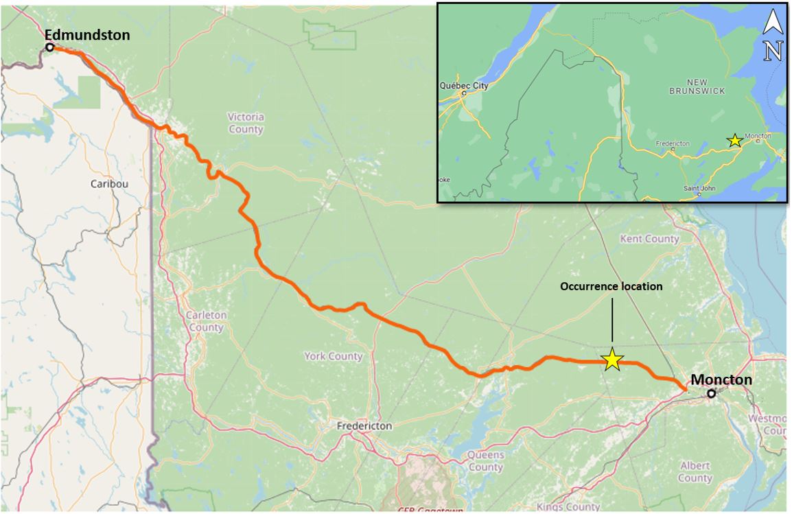
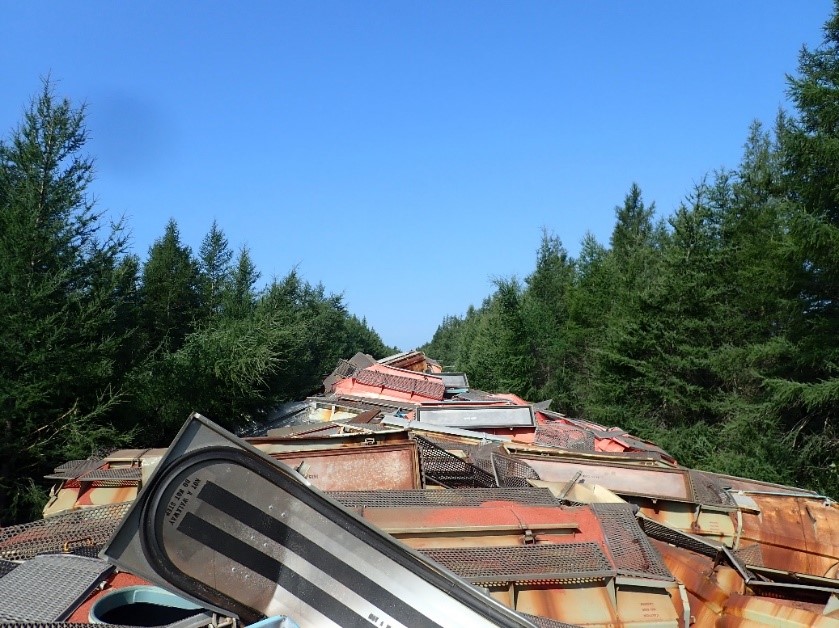
On 21 August 2021, at approximately 1300 Atlantic Daylight Time, Canadian National Railway Company train B73041-15 was travelling eastward at 39 mph on the Napadogan Subdivision when it derailed 30 hopper cars loaded with potash at around Mile 18.9 near Pangburn Station, New Brunswick. As a result of the derailment, 27 of the 30 cars were breached, releasing most of their product. There were no dangerous goods involved and no fire. No one was injured.
1.0 Factual information
On 21 August 2021, Canadian National Railway Company (CN) train B73041-15, a freight train loaded with potash, departed EdmundstonFootnote 1 en route to Moncton, travelling eastward on the CN Napadogan Subdivision.
The train was a unit trainFootnote 2 operated in a distributed power configuration. It consisted of 2 head-end locomotives (CN 3888 and CN 2908), 133 hopper cars loaded with potash, and 2 remote-controlled locomotives at the tail end (CN 3824 and CN 2849). It weighed 19 852 tons and measured 6552 feet.
Each hopper car measured about 47 feet, with a loaded weight of 286 000 pounds.
The crew consisted of a locomotive engineer (LE) and a conductor; both crew members met established rest and fitness requirements and were qualified for their respective positions.
1.1 The occurrence
The train was travelling at the authorized speed of 50 mph on a descending grade when it approached an area under a permanent slow order (PSO) at Mile 19.8, which restricted train speed to 40 mph. There was an advance speed restriction sign near Mile 21.5. Approximately 1700 feet before entering the PSO zone, the LE applied the dynamic brakes (DB) in combination with the train air brakes. The train began decelerating and entered the PSO zone at 47 mph. Approximately 2 minutes later, at 1249,Footnote 3 the train speed had been reduced to 39 mph when a train-initiated emergency brake application occurred. Once the train had stopped, at 1250, it was determined that 30 cars had derailed and that 27 of the derailed cars had breached, releasing product. There were no dangerous goods involved in the derailment and no fire. No one was injured.
The derailment occurred in a remote location at Mile 18.9 near Pangburn Station, approximately 32 km west of Moncton (Figure 1).
1.2 Site examination
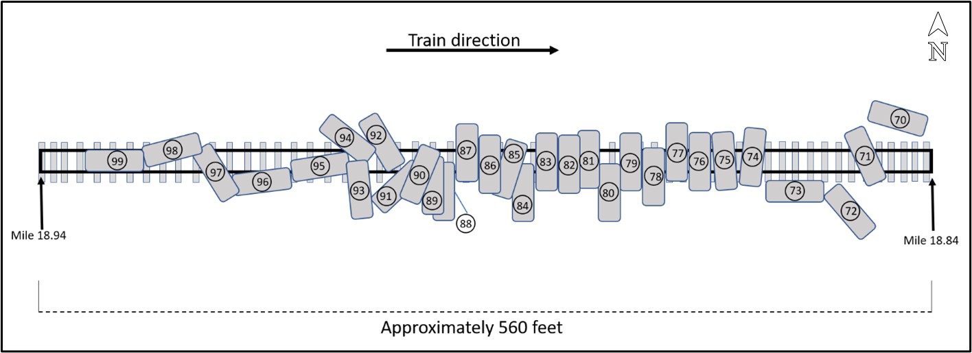
The head end of the train had come to a stop at around Mile 17.80. The 2 head-end locomotives and the first 69 cars had remained on the track. Behind these, 30 cars (positions 70 to 99) had derailed (Figure 2). The cars at the tail end of the train (positions 100 to 133) followed by the 2 remote-controlled locomotives had not derailed.
The derailed cars were in an area covering approximately 560 feet, starting at Mile 18.84 and extending to Mile 18.94 (Figure 3). They had come to rest in various positions along the right-of-way:
- The first 2 derailed cars (positions 70 and 71) were upside down—the 1st to the north of the track, the other over the track bed.
- The next 2 derailed cars (positions 72 and 73) were upright, to the south side of the track.
- The remaining derailed cars were mostly perpendicular to the track bed, in a jackknife pattern over the top of the track bed.
The derailed cars in positions 71, 75, 76, and 77 had bent or broken draft assembly components.Footnote 4 All breaks in the draft assembly components appeared to be clean, with no visible pre-existing defects, indicating that the components had broken as a result of the accident.
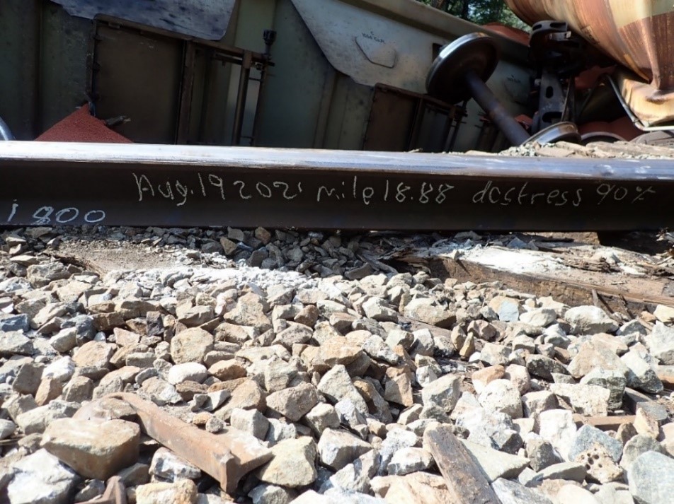
A piece that had broken off the coupler on the 2nd derailed car (position 71) was found at Mile 18.88, about 500 feet from the car’s final resting position at Mile 18.84. The track structure under the derailed cars was completely destroyed. Some pieces of rail found in the wreckage had chalk marks, indicating that track work had recently been performed in the area. On a piece recovered from the north rail, the mark read “Aug. 19 2021 mile 18.85.” On a piece recovered from the south rail, the mark read “1800 Aug. 19 2021 mile 18.88 destress 90 °F” (Figure 4).
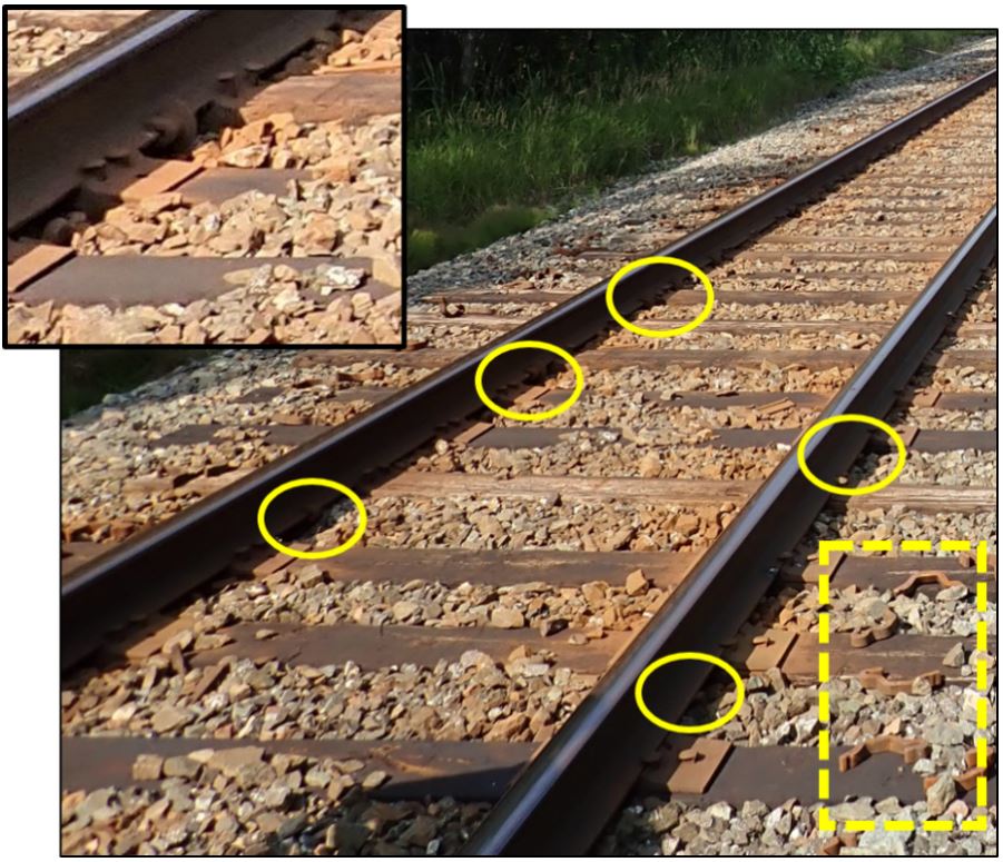
West of the derailment site, track anchors had shifted away from the ties, and there were signs of rail movement across the anchors and ties (Figure 5). On the ground, there were new anchors not yet installed. To the east, from Mile 18.2 to Mile 18.88, the installed anchors looked new, consistent with track work having been performed.
1.3 Weather information
At the time of the occurrence, the visibility was good with partly cloudy skies. The temperature was approximately 25 °C.
In the week before the occurrence, the daytime high temperatures ranged from 25 °C to 31 °C, and the nighttime low temperatures ranged from 11 °C to 18 °C (Table 1).
| Date | Daytime high temperature (°C) | Nighttime low temperature (°C) | Atmospheric conditions |
|---|---|---|---|
| 2021-08-14 | 31.2 | 18.0 | Clear |
| 2021-08-15 | 26.5 | 13.1 | Clear |
| 2021-08-16 | 25.0 | 11.0 | Clear |
| 2021-08-17 | 29.2 | 12.6 | Clear |
| 2021-08-18 | 28.1 | 14.9 | Partially clear |
| 2021-08-19 | 29.4 | 18.4 | Clear |
| 2021-08-20 | 30.1 | 17.2 | Partially clear |
| 2021-08-21 | 25.2 | 15.2 | Partially clear |
1.4 Recorded information
1.4.1 Forward-facing camera
The lead locomotive was equipped with a forward-facing camera. Based on a review of the recording, there were no track anomalies as the head end of the train passed over the occurrence site.
1.4.2 Locomotive event recorder
Each locomotive was equipped with a locomotive event recorder (LER). Table 2 lists significant train handling events based on data downloaded from the head-end and tail-end locomotives, from the time the train started to decelerate at Mile 20.58 until it came to a stop at Mile 17.80.
| Time | Mile | Event | Lead locomotive tractive effort (KIPS) | Trailing locomotive tractive effort (KIPS) | Train speed (MPH) |
|---|---|---|---|---|---|
| 1246:27 | 20.58 | The LE begins decreasing throttle from position 5 to idle. | 0 | 0 | 50 |
| 1246:34 | 20.48 | The LE sets the throttle to idle. | 0 | 0 | 50 |
| 1246:39 | 20.41 | The LE makes a minimum air brake application (7 psi). | 0 | 0 | 50 |
| 1247:00 | 20.12 | The LE sets up the DB; distributed power is still operating in synchronous mode. | 0 | 0 | 50 |
| 1247:17 | 19.89 | The LE starts to increase the DB from position 1 to position 8 (maximum position); the operation takes 9 seconds to complete. | 9 | 5 | 49 |
| 1247:33 | 19.80 | The head end of the train enters the PSO zone. Speed is approximately 47 mph. | 39 | 39 | 47 |
| 1248:00 | 19.71 | The LE releases the air brakes. | 42 | 42 | 44 |
| 1248:07 | 19.24 | The LE decreases the DB to position 4. | 30 | 43 | 44 |
| 1248:15 | 19.14 | The LE increases the DB to position 5. | 25 | 23 | 43 |
| 1248:17 | 19.12 | The LE decreases the DB to position 4. | 22 | 24 | 43 |
| 1248:31 | 18.95 | The LE increases the DB to position 5. | 26 | 25 | 42 |
| 1248:36 | 18.89 | The LE increases the DB to position 6. | 32 | 29 | 42 |
| 1249:04 | 18.57 | The LE decreases the DB to position 3. | 19 | 37 | 41 |
| 1249:13 | 18.47 | The LE increases the DB to position 4. | 21 | 19 | 41 |
| 1249:26 | 18.46 | The train speed decreases to 39 mph. | 27 | 28 | 39 |
| 1249:31 | 18.27 | The LE decreases the DB to position 2. | 18 | 28 | 39 |
| 1249:34 | 18.24 | The LE decreases the DB to position 1. | 11 | 16 | 39 |
| 1249:40 | 18.17 | The LE sets the DB to the OFF position. | 0 | 2 | 39 |
| 1249:42 | 18.15 | A train-initiated emergency brake application occurs as the train is travelling at 39 mph. | 0 | 0 | 39 |
| 1250:32 | 17.80 | The train comes to a stop. | 0 | 0 | 0 |
1.5 Subdivision information
The Napadogan Subdivision consists of a single main track that extends east to west from Pacific Junction, near Moncton (Mile 0.0), to Edmundston (Mile 219.4). Train movements are governed by the centralized traffic control system, as authorized by the Canadian Rail Operating Rules, and dispatched by a rail traffic controller located in Edmonton, Alberta.
In 2020, traffic on the subdivision was 17.7 million gross ton-miles per mile.
1.6 Track information
The track on the Napadogan Subdivision is a Class 4 track under the Transport Canada–approved Rules Respecting Track Safety, also know as the Track Safety Rules (TSR).
In the area of the derailment, the track is on a 0.4% grade and runs through the Canaan Bog Protected Natural Area; there are soft substrate conditions due to the bog.
The track has a speed limit for freight trains of 55 mph from Mile 34.8 to Mile 19.8, with the exception of any slow order. From Mile 19.8 to Mile 18.2, train speed is restricted to 40 mph by a PSO.Footnote 5 There are advance speed restriction signs placed approximately 1.7 miles from either end of the PSO zone. These signs were in place at the time of the derailment and were not obstructed.
The track structure in the area of the derailment consisted of continuous welded rail (CWR); some rails were 132 pounds, others were 136 pounds.Footnote 6 The rails lay on 8-foot hardwood ties, except from about Mile 19.5 to Mile 18.8, where 12-foot ties were used as part of the mitigation measures implemented for the bog conditions. The general condition of the ties was within the standards set out in the TSR.Footnote 7 The rail was secured to the hardwood ties with double-shouldered tie plates, some 12 inches, others 14 inches, with a mixed spike pattern. The ballast was 3-inch mainline ballast, clean, with good drainage.
1.6.1 Track inspections
For federally regulated track, the regulatory requirements for track maintenance and inspections are set out in the TSR, which are the minimum safety requirementsFootnote 8. According to the TSR, Class 4 CWR track with annual traffic between 15 and 35 million gross tons must
- be visually inspected (on foot or in a track vehicle) twice weekly,Footnote 9
- receive an electronic geometry car inspection by a heavy geometry inspection vehicle twice annually,Footnote 10,Footnote 11 and
- receive a rail flaw inspection 3 times annually.Footnote 12
Inspections of the Napadogan Subdivision were conducted in accordance with regulatory requirements. The latest inspections were as follows:
- a visual inspection by hi-rail vehicle on 20 August 2021
- the last inspection using a heavy geometry vehicle was on 08 July 2021, and an inspection using a light geometry vehicle on 06 August 2021
- a rail flaw inspection using ultrasonic testing technology on 15 July 2021
No defects were reported.
1.7 Thermal stress in continuous welded rail
Steel expands under heat and contracts under cold conditions, subjecting the rail to thermal forces. Forces exerted by expansion and contraction of the rail create stress in the material and structure of the track. As CWR is fixed along its length, its freedom of longitudinal expansion and contraction is limited, making it especially susceptible to thermal stress.
The compressive forces exerted when a rail’s temperature increases can cause track buckling (lateral deformation of the track), while the tensile forces that occur when a rail cools and shrinks can lead to increased track alignment irregularities, track pull-apart failures at joints, or rail fractures.
The temperature of the rail is affected by the ambient temperature, and heat buildup from direct exposure to sunlight. According to CN’s Engineering Track Standards, “on a sunny day, the rail temperature can be 30 °F, or 17 °C warmer than the ambient temperature. Cloud cover, wind and precipitation can reduce this difference.”Footnote 13
Rail temperature is also affected by the passage of trains, especially during braking, which generates friction heat from the wheel contact with the rail.
1.7.1 Rail neutral temperature
The neutral temperature of a rail is the temperature at which it is free of any tensile or compressive stress. CWR is installed at a temperature (the preferred rail laying temperature) determined for each operating area.Footnote 14 Over a rail’s service life, ambient temperature variations, track maintenance, and traffic-induced movements can cause a redistribution of the internal stresses in the rail, thus lowering the neutral temperature over time. When the neutral temperature of a rail is lowered, compressive stresses in the rail begin to build at a lower ambient temperature. This scenario creates instability in the track and lowers its resistance to compressive thermal stress.
1.7.2 Mitigation of rail stress
To mitigate the buildup of excessive stress in CWR, railways conduct track destressing work, which consists of cutting the rail and removing anchors to release any built-up stress and return the rail to its neutral temperature. During this process, the rail should be kept as near to the preferred rail laying temperature as possible. Once the stress is released, any excess rail is removed or new rail is added if required. The rails are then welded back together and re-anchored.
1.8 Track destressing work in the area of the occurrence
The track in the vicinity of the derailment had shown previous signs of tie and anchor movement and was identified in 2020 by CN as requiring preventive maintenance. Rail destressing and anchor replacement was scheduled to be performed from Mile 18.2 to Mile 19.9.
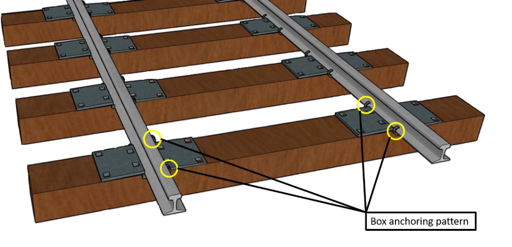
The destressing work began on 17 August 2021, working east to west. As part of this effort, reinstalled rails were box-anchored, which means that the rails were secured with 4 anchors per tie (Figure 6). Box anchoring creates a fixed point in the track, which is considered one of the most secure ways to anchor a track and prevent movement. In contrast, the section of track that was not destressed had intermittent anchors (1 or 2 per tie), and some had shifted away from the tie, providing less securement.
On 19 August 2021, the work was completed to Mile 18.88 on the south rail and to Mile 18.85 on the north rail, with plans to return the following week. The location where the destressing work stopped was indicated by chalk markings on the rails.
1.9 Hot weather inspections
To detect signs of thermal stress in rail and to identify areas of track susceptible to buckling, railway workers routinely perform visual inspections by hi-rail vehicles for signs of compressive thermal rail stress.
CN’s hot weather inspection standard for CWR indicates that, when ambient temperatures reach or are expected to reach 30 °C or higher, hot weather inspections must be conducted and, if warranted, speed restrictions must be issued for the affected areas.Footnote 15
Current inspection methods rely on judgment by track maintenance workers, who must check the track structure for physical signs of degradation, such as:
- misalignment, for instance flats in a curve or kinks in tangent sections of track,
- insufficient ballast at the ends of the ties,
- poor contact of the rail anchors,
- movement of the rail through the rail anchors, and
- ballast disturbance caused by movement of ties.
Visual inspections have their limitations. Because broad geographic areas are affected by high heat conditions, employees must physically inspect a large territory. Inspections must be conducted during the high heat of the day, which is often limited to a few hours. Physical signs of thermal stress may not always be visible from a moving hi-rail vehicle. To help address these limitations, employees have access to temperature-measuring devices to determine the rail temperature. There are also rail stress measuring devices such as the VERSE (vertical rail stress equipment) tool, which can be used to spot check the levels of rail stress in problematic areas. However, this technology requires the track securements to be removed during testing.
While there is ongoing research for non-destructive testing technologies for rail temperature and thermal stress monitoring, there currently is no widely used or accepted method beyond visual inspections and tools for spot checking.
In the week before the occurrence, hot weather inspections were conducted on each day that the temperature reached 30 °C. The latest hot weather inspection was conducted on 20 August 2021; no signs of rail instability or track susceptibility to buckling were reported in the area of the occurrence.
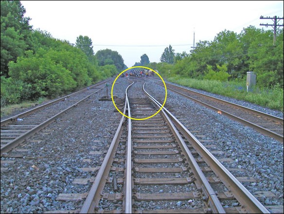
1.10 Track buckles
A track buckle is a lateral shift of the track that occurs when longitudinal compressive stress in the rail overcomes the lateral resistance of the track structure (Figure 7). Track buckles can occur when there is an increase in the longitudinal compressive stress or when there is a decrease in the lateral resistance of the track structure. Track buckles are more likely to occur in the presence of compressive stress.
Zones of tight rail are areas where compressive stresses are present. Theses zones can develop at locations where trains exert high longitudinal forces, such as on descending grades or in curves; longitudinal forces are higher during acceleration and braking. These zones can also develop at locations of soft subgrade such as bogs, where the rail moves excessively under traffic, causing ties to skew and bunch up. The formation of these zones becomes more likely in high traffic areas or when the track structure is not well maintained.
To prevent the development of zones of tight rail in CWR, the rail must be properly supported and secured. Restraining the rail longitudinally and laterally is dependent upon having sound ties, sufficient spikes and anchors, and clean crushed rock ballast. If one or more of these track components are not contributing to the expected resistance to these longitudinal forces, compressive stress can overcome the lateral stability of the track, creating favourable conditions for a track buckle.
1.11 Train traffic in the area of the derailment
Table 3 shows traffic volumes in the area of the derailment after destressing work was stopped on 19 August 2021 until the derailment, based on data from a wayside detector located at Mile 27. Eastbound traffic was in the early morning, with the exception of the occurrence train, which travelled through the area in the early afternoon on 21 August 2021. Including the occurrence train, there was 39% more tonnage moving eastbound (descending the grade) than westbound.
| Date | Time | Direction | Number of axles | Number of rail cars | Train length | Train tonnage |
|---|---|---|---|---|---|---|
| 2021-08-20 | 0113 | East | 392 | 105 | 7140 | 7285 |
| 2021-08-20 | 0339 | East | 626 | 208 | 13 870 | 13 258 |
| 2021-08-20 | 0555 | West | 622 | 207 | 13 554 | 12 583 |
| 2021-08-20 | 0625 | West | 626 | 155 | 8917 | 7383 |
| 2021-08-20 | 1201 | West | 586 | 145 | 9954 | 10 465 |
| 2021-08-21 | 0343 | East | 650 | 161 | 10 713 | 14 986 |
| 2021-08-21 | 0437 | East | 610 | 214 | 13 705 | 14 041 |
| 2021-08-21 | 0716 | West | 522 | 187 | 11 489 | 8287 |
| 2021-08-21 | 0832 | West | 542 | 187 | 12 044 | 11 208 |
| 2021-08-21 | 1238* | East | 556 | 137 | 6552 | 19 852 |
* The occurrence train
1.12 Track-train dynamics
Track-train dynamics is the interaction between a train in motion and the geometry of the track, and encompasses the dynamic forces that can occur between the rolling stock wheels and the rail.
A train travelling on tangent track will generate steady-state longitudinal draft (tensile) and buff (compressive) in-train forces, mainly as a result of throttle or DB modulations and air brake applications and releases. On ascending grades, the train will be stretched and generate draft forces; the magnitude of these forces is based on train trailing tonnage, the steepness of the grade, and train rolling resistance. On descending grades, the train will be bunched and generate dynamic buff forces; the magnitude of these forces is based on train trailing tonnage, the steepness of the grade, and locomotive DB and air brake retardation. The forces created by trains operating on grades are mitigated by the use of DP locomotives within the train consist.
Longitudinal forces are transferred into the track through the interactions between the rails and the wheels of the rolling stock while in motion. These forces are generally higher at the locomotive consist due to tractive and retarding efforts. Wheel oscillation from rolling stock movement also generates lateral forces, which push on the rail and add more dynamic forces between the train and the track. These forces can be lessened through wheel design and rolling stock truck design. The magnitude of the lateral forces is determined by several factors, including the longitudinal forces of the train, the grade of the track, the degree of track curvature, and the presence of worn mechanical components. Steep track gradients and sharp curves are associated with producing higher lateral forces than that of tangent track. At the time of the derailment, the train was operating on tangent track and the lateral forces were nominal.
1.12.1 Cyclic loading
Cyclic loading is the continuous and repeated application of a load, such as the passage of trains on railway track.
Unit trains have a particularly significant effect on the cyclic loading of track. This is because unit train consists are usually uniform; that is, all cars are of the same design and loading, with the car trucks and car bodies responding more or less as one unit. Therefore, each rail car on the train responds to track irregularities in the same manner as the previous car, thereby concentrating cumulative impacts at whatever irregularities are encountered in the track structure. Trains with numerous rail cars of the same design and with high load capacity provide the track little or no opportunity for elastic recovery during their passage.
1.13 Train handling
Train handling refers to managing the operating characteristics of a train over a given territory. These include train length, tonnage, weight distribution, and train slack action in response to undulating terrain, grade, and curvature over which the train is operated.
Train operators must anticipate the train’s buff and draft response and must adapt the train’s operation (using a combination of throttle modulation, locomotive DB and train air brakes) to negotiate changes in terrain.
Planning and situational awareness are the key factors in good train handling, especially with heavy trains. With a ratio of 142.9 tons per operative brake, the occurrence train was considered short and heavy.
According to CN’s Locomotive Engineer Operating Manual, it is important for LEs to use sound judgment when controlling speed, slowing, or stopping a train. The manual states, in part:
The objectives are to minimize forces transmitted to the track structure, and to minimize in-train forces making full use of:
– advance planning;
– throttle manipulation;
– gradual application and release of throttle, DB, and automatic brake;
– proper balance between the use of DB and automatic brake.Footnote 16
In this occurrence, the manner in which the dynamic and train air brakes were used did not sufficiently slow the train to meet the PSO speed restriction. As a result, the train entered the PSO zone at a speed of 47 mph, 7 mph over the limit.
Finding: Other
Although the train handling in this occurrence did not fully conform to CN’s operating procedures, the investigation was unable to determine whether improved train handling would have sufficiently reduced the stresses to avoid the accident.
1.13.1 Dynamic brake applications
The DB system is a supplementary braking system available on the locomotives only. It uses energized traction motor magnetic fields to create a resistance that helps to slow the train. The DB system is preferred in train operations to control train speed as it does not take up air from the train consist, has a graduated release, and promotes fuel efficiency. DB has significant retarding force when it is in use. The air brake system provides additional braking effort, when required.
DB tends to generate higher buff forces throughout the train than the automatic air brakes. DB application concentrates braking effort at the locomotives, which will typically result in the rail cars bunching together as train slack compresses. For this reason, DB should be applied gradually and incrementally to avoid excessive forces.
1.14 TSB laboratory assessment of train handling and in-train forces
The TSB laboratory reviewed the LER data and performed a train dynamics simulation using the Train Energy and Dynamics Simulator (TEDS) software program to assess train handling and in-train forces in this occurrence.
Based on the LER data, it was determined that, shortly before the train entered the 40 mph PSO zone, there was a heavy application of the dynamic brakes (DB effort was increased to maximum—from position 1 to position 8—in 9 seconds). The train entered the PSO zone at an approximate speed of 47 mph and had decelerated to about 39 mph when the train-initiated emergency brake application occurred.
The results of the train dynamics simulations indicated that, before the train-initiated emergency brake application, the maximum simulated draft forces were about 60 to 85 kips,Footnote 17 and the maximum simulated buff forces were about 70 to 90 kips. These forces, which take into consideration the heavy application of the DB and the speed of the train at the time of the train-initiated emergency brake application, would not have been sufficient to break couplers with no pre-existing defect nor cause rail rollover of track in good condition.
The TSB laboratory concluded the following regarding the factors that may have contributed to track failure in this occurrence:
- The track in the area of the derailment was on a 0.4% grade. Tractive efforts of trains ascending the grade and compressive efforts of trains descending the grade could cause a reduction of the rail neutral temperature.
- The longitudinal forces induced in the rail by the dynamic braking were about 80 kips.
- It is very likely that the dynamic forces from the passing train, combined with compressive thermal stresses, accelerated track deformation growth, initiating a track buckle, which led to the derailment.
1.15 Previous occurrences involving track buckles
In the 5 years preceding this occurrence, 15 train derailments involving a track buckle were reported to the TSB, one of which (R19C0088) was the subject of an investigation report. Footnote 18
1.16 TSB laboratory reports
The TSB completed the following laboratory report in support of this investigation:
- LP122/2021 – In-Train Force Analysis
2.0 Analysis
Although broken draft assembly components were found on site, it is considered that these components were damaged as a result of the derailment sequence and did not play a contributing role in the accident. Therefore, the analysis will focus on the management, detection and mitigation of thermal stress in continuous welded rail (CWR), and on track-train dynamics.
2.1 The occurrence
On 21 August 2021 at about 1300, Canadian National Railway Company (CN) train B73041-15, a freight unit train loaded with potash, was travelling eastward at 39 mph on the CN Napadogan Subdivision when a train-initiated emergency brake application occurred near Pangburn Station (Mile 18.9), leading to the derailment of 30 cars. At the time of the occurrence, the train was decelerating on a descending grade within a permanent slow order (PSO) zone. This heavy unit train was also the only eastbound train that had travelled through the area during afternoon hours, when the ambient temperature would have been at its highest, since destressing work had stopped on 19 August 2021.
Most of the derailed cars were in a jackknife pattern, indicating a possible sudden track failure. A piece of coupler that had broken off the 2nd derailed car (position 71) was found about 500 feet from the car’s final resting position, which suggests that the car dropped off the track and travelled about 500 feet before coming to rest. This is consistent with the track having buckled under the train.
Finding as to causes and contributing factors
The derailment occurred when the track buckled under the train as it was decelerating on a descending grade near Pangburn Station.
2.2 Thermal stress in continuous welded rail
Thermal rail stress occurs when the steel rail is subjected to temperature variations. Under heat, steel expands, creating compressive forces; under cold conditions, it contracts, creating tensile forces. CWR is especially susceptible to thermal stress as it is fixed along its length, which limits its freedom of expansion and contraction. Compressive forces exerted on rails can cause track buckling, while tensile forces can lead to pull-aparts and fractures of the rail.
High ambient temperatures and exposure to direct sunlight increase a rail’s temperature, subjecting it to compressive thermal stress. On the day of the occurrence, the ambient temperature was about 25 °C and there were periods of direct sunlight. This could have increased the rail temperature up to another 17 °C, potentially bringing the rail temperature beyond 40 °C, creating the conditions for compressive thermal stress in the rail.
Finding as to causes and contributing factors
High ambient temperatures and exposure to direct sunlight on the day of the occurrence contributed to the buildup of compressive thermal stress in the rail.
2.2.1 Rail neutral temperature
To lower the risks associated with thermal stress, CWR is installed at a temperature as near as possible to the rail neutral temperature (the temperature at which it is free of any tensile or compressive stress).
Over a rail section’s service life, a rail’s neutral temperature can decrease due to external factors such as seasonal fluctuations of ambient temperatures, track maintenance activities, and traffic-induced movements. When the neutral temperature of a rail decreases, its resistance to compressive stress is reduced.
To mitigate the buildup of excessive internal stress in CWR, railways conduct track destressing activities, release built-up stress, and return the rail closer to its neutral temperature.
Track in the vicinity of the derailment was identified as requiring destressing and anchor replacement. Track destressing work was being performed in sections of the subdivision to bring the rail back to CN’s preferred rail laying neutral temperature of 32 °C (90 °F). The sections of track that had not yet undergone destressing likely had a lower neutral temperature than 32 °C. Consequently, they had a lower resistance to compressive forces, and these forces would also have begun to build at a lower ambient temperature.
Finding as to causes and contributing factors
The neutral temperature of the rail had decreased over its service life, creating instability at lower ambient temperatures and reducing the ability of the rail to resist buckling when subjected to compressive stress.
2.2.2 Hot weather inspections
To identify rail with excessive thermal stress, track maintenance employees typically conduct visual inspections by hi-rail vehicles, looking for indications of built-up longitudinal stress, such as lifted spikes and rail movement or instability.
Visual inspections can only detect physical signs of track degradation at a particular location on a section of rail. They do not allow the advance identification of harmful levels of residual compressive stress in undisturbed rail or track structure. Consequently, tracks with rails under excessive compressive stress could remain undetected.
Stress measuring devices such as the VERSE (vertical rail stress equipment) tool can also be used to help determine the amount of stress in the rail. This tool measures stress of the rail in a specific location; however, this technology is limited in its practical application because it requires the track securements to be removed during testing.
In this occurrence, a hot weather inspection carried out on the day before the occurrence did not identify any sign of rail instability or track susceptibility to buckling due to excessive compressive thermal stress.
Finding as to risk
If rail instabilities due to excessive thermal stress are not effectively identified and if precautionary measures are not implemented, railway tracks could buckle in service, increasing the risk of a derailment.
2.3 Track–train dynamics
Trains in motion exert longitudinal forces on rolling stock, mainly as a result of throttle or dynamic brake (DB) modulations, and brake applications and releases. These longitudinal forces are transferred into the track through the interactions between the rails and the wheels of the locomotives and rolling stock while in motion, and contribute to the stresses imposed on the rails. Rolling stock variations and movements that also generate lateral forces can push on the rail, adding more dynamic forces between the train and the track. Although the design of wheel profiles and truck frames help mitigate wheel flange contact with the rail and its impact on lateral forces, as these components wear, the impact of these mitigations can be lessened.
In this occurrence, as the train was travelling on a descending grade, there was an application of the DB, which generated longitudinal buff forces shortly before the derailment. According to TSB laboratory calculations, the forces induced in the rail by the dynamic braking were about 80 kips, which are considered to be within the parameters of normal train operations. The passage of trains creates friction heat from the wheel contact with the rails. These forces added to the compressive stress that was already present in the rail due to the high ambient temperature.
Finding as to causes and contributing factors
The longitudinal forces applied to the track as the train was decelerating contributed to an increase of compressive stress in the rail.
2.4 Condition of the track
To withstand train-induced forces, railway tracks must be properly supported and secured. Restraining rails longitudinally and laterally is dependent upon having sound ties, sufficient spikes and anchors, and clean crushed rock ballast. If one or more of these track components are not contributing to the expected resistance to the longitudinal forces exerted by passing trains, compressive stress can overcome the lateral stability of the track, creating favourable conditions for a track buckle.
The track in the area of the derailment was inherently more susceptible to movement due to the bog conditions and the grade. To reduce the risks of rail movement associated with these conditions, a PSO was in effect.
Track securement appropriate for the bog conditions had been done in the area, with longer ties used as a mitigation measure. However, there were signs, such as tie and anchor movement, that rail anchoring had degraded over time.
The track in the area of the derailment had been identified in 2020 by CN as requiring preventive maintenance, and at the time of the occurrence, it was undergoing destressing work. The work had begun on 17 August 2021, going east to west. At the time of the occurrence, destressing was partially completed to Mile 18.88 on the south rail and to Mile 18.85 on the north rail, with plans to return the following week.
In the section of track where the destressing work had been performed, the rails were box-anchored. Box anchoring creates a fixed point on the track and is considered the most secure way to anchor a track and prevent movement. In contrast, the section of track that had not yet been destressed was less tightly secured due to the degraded anchoring, and allowed more movement of the rail.
Findings as to causes and contributing factors
Degraded condition of rail anchoring on the non-destressed sections reduced the strength of the track and its resistance to movement.
The combination of compressive thermal stress and the longitudinal forces from the braking train on a track with a lower rail neutral temperature and degraded rail anchoring likely initiated the track buckle.
3.0 Findings
3.1 Findings as to causes and contributing factors
These are conditions, acts or safety deficiencies that were found to have caused or contributed to this occurrence.
- The derailment occurred when the track buckled under the train as it was decelerating on a descending grade near Pangburn Station.
- High ambient temperatures and exposure to direct sunlight on the day of the occurrence contributed to the buildup of compressive thermal stress in the rail.
- The neutral temperature of the rail had decreased over its service life, creating instability at lower ambient temperatures and reducing the ability of the rail to resist buckling when subjected to compressive stress.
- The longitudinal forces applied to the track as the train was decelerating contributed to an increase of compressive stress in the rail.
- Degraded condition of rail anchoring on the non-destressed sections reduced the strength of the track and its resistance to movement.
- The combination of compressive thermal stress and the longitudinal forces from the braking train on a track with a lower rail neutral temperature and degraded rail anchoring likely initiated the track buckle.
3.2 Findings as to risk
These are conditions, unsafe acts or safety deficiencies that were found not to be a factor in this occurrence but could have adverse consequences in future occurrences.
- If rail instabilities due to excessive thermal stress are not effectively identified and if precautionary measures are not implemented, railway tracks could buckle in service, increasing the risk of a derailment.
3.3 Other findings
These items could enhance safety, resolve an issue of controversy, or provide a data point for future safety studies.
- Although the train handling in this occurrence did not fully conform to CN’s operating procedures, the investigation was unable to determine whether improved train handling would have sufficiently reduced the stresses to avoid the accident.
4.0 Safety action
4.1 Safety action taken
Following the derailment, Canadian National Railway Company issued Operating Bulletin No. 618. This bulletin instructed train crews to avoid excessive braking and limit the dynamic brakes to position 5 or less from Mile 17.0 to Mile 21.2 of the Napadogan Subdivision.
This report concludes the Transportation Safety Board of Canada’s investigation into this occurrence. The Board authorized the release of this report on . It was officially released on .