Gas pipeline rupture
Westcoast Energy inc., carrying on business as
spectra energy transmission
Nig Creek pipeline, kilometre Post 1.93
near Buick, British Columbia
The Transportation Safety Board of Canada (TSB) investigated this occurrence for the purpose of advancing transportation safety. It is not the function of the Board to assign fault or determine civil or criminal liability. This report is not created for use in the context of legal, disciplinary or other proceedings. See Ownership and use of content. Masculine pronouns and position titles may be used to signify all genders to comply with the Canadian Transportation Accident Investigation and Safety Board Act (S.C. 1989, c. 3).
Summary
At 2305 Pacific Standard Time on 28 June 2012, a pipeline rupture and ignition occurred on Westcoast Energy Inc.'s 406.4 mm (16-inch) Nig Creek pipeline, located about 40 km northwest of Buick, British Columbia. Approximately 25 minutes later, a pipeline rupture and ignition occurred on Bonavista Energy Corporation's 168.3 mm (6.625-inch) pipeline installed nearby in the same right-of-way. At the time of the ruptures, both pipelines had been shut down and contained pressurized sour gas. The fire spread to adjacent forested areas. A large crater was created and one piece of the Nig Creek pipe was ejected along with other debris to approximately 20 m from the rupture site. There were no injuries and no evacuation was required.
Factual information
At 2305Footnote 1 on 28 June 2012, the 406.4 mm (16-inch) Nig Creek pipeline, owned by Westcoast Energy Inc. (Westcoast), which was carrying on business as Spectra Energy Transmission, ruptured at Kilometre Post (KP) 1.93. Sour gas escAPIng from the ruptured pipeline ignited and the resulting fire spread to the adjacent forested area. At the time of the occurrence, the pipeline pressure was 6654 kilopascals (kPa).
Approximately 25 minutes later, the 168.3 mm (6.625-inch) Bonavista Energy Corporation (Bonavista) pipeline, located nearby in the same right-of-way, ruptured and the escaping sour gas also ignited. The pipeline pressure and temperature were 869 kPa and 12°C.
At the time of the occurrence, the weather was 14°C with cloudy periods.
The total volume of gas released was 955 000 m³ (approx.) for the Nig Creek pipeline and 6 400 m³ (approx.) for the Bonavista pipeline. The total area burned was approximately 1.6 hectares. There were no injuries and no one was evacuated.
The land surrounding the occurrence site was unsurveyed Crown land located in the Peace River Regional District and owned by the province of British Columbia. The occurrence area (see Figure 1) was sparsely populated, with no homes within 12 km. The nearest road is situated approximately 400 m to the north. Highway 97 is approximately 30 km southwest. The nearest town is Buick, British Columbia, located approximately 40 km to the southeast, with a population of 58 residents.
Westcoast's Nig Creek pipeline
The Nig Creek pipeline is part of Westcoast's sour gas gathering system in northern British Columbia. The pipeline originates at Nig Creek booster station No. 9 (BS-9) and ends at Buick Creek booster station, 45.6 km downstream.
Sour gas arrives at the BS-9 station inlet through a number of gathering lines and other pipelines. At the booster station, the collected sour gas is compressed if required and injected into the Nig Creek pipeline using a system of piping and controls. Additional sour gas is also gathered from various producer receipt points along the pipeline. The sour gas is transported to Westcoast's McMahon gas processing plantFootnote 2 (McMahon plant) for processing.
At the time of the occurrence, the compressor units at the BS-9 station were not operating, and there was no flow through the pipeline due to the unplanned outage of the McMahon plant. When gas flow into the plant is interrupted, sour gas being produced continues to enter the upstream pipeline network and accumulates in the gathering lines. This results in a steady increase of upstream system pressure until the entire gathering network reaches a uniform pressure or until pressure control devicesFootnote 3reach their activation set points.Footnote 4
The Nig Creek pipeline was designed and constructed in 1960 to the American Standards Association (ASA) B31.1.8 code. The 406.4 mm external diameter pipeline has a wall thickness of 6.35 mm. It is constructed to the American Petroleum Institute (API) Grade 52 mild carbon steel, which has a specified minimum yield strength (SMYS) of 359 megapascals (MPa). The pipeline's maximum operating pressure (MOP) as authorized by the National Energy Board (NEB) is 6895 kPa.
The longitudinally welded pipe sections were manufactured in 1960 using low-frequency electric resistance welding. The pipe sections were joined in the field using manual shielded metal arc welding. At the time of construction, there were no requirements to conduct non-destructive examination of electric resistance welds and radiographic inspection was typically performed randomally on 10% of the production girth welds. The pipeline was externally coated with a field-applied asphalt enamel coating.
Bonavista pipeline
The Bonavista pipeline, which is under the jurisdiction of the British Columbia Oil and Gas Commission, was put into service in 1967 with a MOP of 3500 kPa. This pipeline, which was acquired by Bonavista in 2005, forms part of the co MPany's sour gas gathering system in Northern British Columbia and is identified as "Project 22830 Segment 1" (Bonavista pipeline). This 5.8 km pipeline segment has an external diameter of 168.3 mm and a wall thickness of 4 mm. It is made up of electric resistance welded pipe composed of API 5L Grade B carbon steel having a SMYS of 240 MPa. During manufacture, it was externally coated with extruded polyethylene.
The Bonavista pipeline shares the same right-of-way with the Nig Creek pipeline, as the pipes are buried parallel to each other, approximately 3 m apart. The two pipelines transport sour gas, but in opposite directions.
Testing and in-line inspection of the Nig Creek pipeline
In November 1960, a post-construction pneumatic pressure test using sour gas was performed. During this test, several pipe joint failures along the longitudinal seam occurred. No records of the number, cause and location of the failures are available.
Due to the urgent need for gas, the pipeline was permitted to operate temporarily at the reduced MOP of 6206 kPa.
In June 1961, following a successful hydrostatic test, the pipeline was then authorized to operate at its design MOP of 6895 kPa.
Since 1961 and prior to the occurrence, no other pressure test had been performed on the Nig Creek pipeline.
A number of internal inspections of the Nig Creek pipeline were performed as follows:
- In 1986, the pipeline was inspected using a standard resolution magnetic flux leakage (MFL) in-line inspection tool.Footnote 5
- In 1995, the pipeline was inspected using a standard resolution MFL in-line inspection tool.
- In 2004, the pipeline was inspected using a high-resolution MFL tool.
During the 3 internal inspections, no pipe defects were detected in the vicinity of the occurrence. However, some external corrosion was identified elsewhere in the pipeline, resulting in the following repairs:
- Following the 1986 inspection, 6 sections of pipe were replaced to remove external corrosion.
- Following the 1995 inspection, 6 sections of pipe were replaced to remove external corrosion.
- Following the 2004 inspection, 3 composite reinforcement sleeves were installed on a pipe joint at approximately KP 32.9.
Cathodic protection and external coating of the Nig Creek pipeline
Controlling external corrosion on a buried pipeline system is normally accomplished using a dual system of external coatings and cathodic protection (CP). The primary purpose of the external coating is to protect the pipe surface from its environment. If the external coating degrades or fails, the CP system is designed to protect the pipe from corrosion.
On the Nig Creek pipeline (including the girth welds), the external coating consists of field-applied asphalt enamel. Since 1960, this external coating had been repaired at several locations along the pipeline as a result of various investigative excavations and repair work following the in-line inspections of 1986, 1995 and 2004. The repair coating consisted of a petroleum-based tape and adhesive primer system.
No repairs were made to the pipeline coating in the i mmediate vicinity of the occurrence, as no defects had been identified.
The Nig Creek pipeline's CP system components, consisting of rectifiers and anode beds, are located at each end of the pipeline. The CP rectifier closest to the occurrence site is located upstream at booster station BS-9. The test stations closest to the occurrence are located at KP 1.360 (upstream) and KP 2.813 (downstream). The 2 most recent CP surveys were performed in July 2010 and November 2011. From these surveys, it was determined that, in the vicinity of the occurrence, the CP system met regulatory requirements as all negative polarized potential readings exceeded 850 millivolts. As such, no remedial action was required.
Recorded information
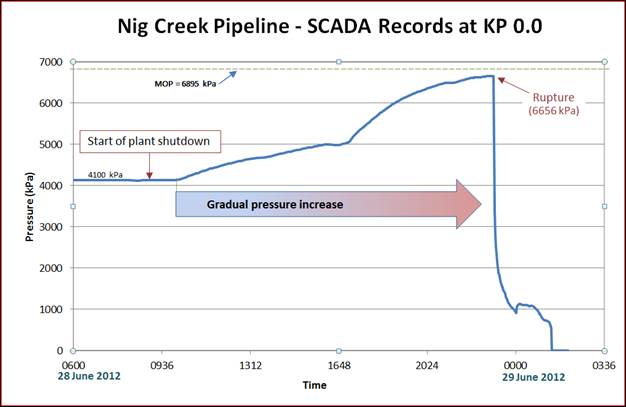
Inlet pressure and flow data from the Nig Creek pipeline's supervisory control and data acquisition (SCADA) records were reviewed for the 2-year period preceding the occurrence (Figure 2.)
Over the 2 year period, the Nig Creek pipeline was operated at an average pressure of 4350 kPa. There were a few times over that period when the pipeline's operating pressure fluctuated for short periods of time, typically 24 to 48 hours. Before June 2012, the previous maximum operating pressure had been 6628 kPa, which occurred on 18 January 2011. Pressure fluctuations on this pipeline typically occur due to operating factors (for example, available supply of gas, maintenance activities and gas processing plant shutdowns).
On the day of the occurrence and starting from approximately 1000, there was a gradual pressure increase in the Nig Creek pipeline from 4100 kPa to 6656 kPa (Figure 3.).
The pressure increase was due to the accumulation of incoming sour gas in the Nig Creek pipeline as a consequence of the McMahon plant shutdown at approximately 0900 on 28 June 2012.
At 2305, at the time of the pipeline rupture, the pressure at KP 0.0 was 6656 kPa,Footnote 6 which was followed by a rapid decompression to approximately 1000 kPa.
On the day of the occurrence, the gas controllers were managing the steady increase in pipeline pressure due to the accumulating gas following the McMahon plant shutdown.
Westcoast's SCADA system
The SCADA system is the overall monitoring and control system of the Westcoast pipeline network. It provides gas control personnel with access to real-time information on line pressures at critical locations throughout the pipeline network. This system also provides important operating parameters for compressor and processing plant facilities and gas quality information for gas deliveries into the pipelines. The SCADA system is used by gas control personnel to operate the compression, pressure control, receipt and delivery facilities both in the raw gas and mainline transmission facilities.
Notification of pipeline rupture
Between approximately 2314 and 2323 on 28 June 2012, 2 sets of low-pressure alarms of medium priority originating from sensors within the BS-9 station were reported by the Westcoast SCADA system and displayed on the system's alarm screens. These screens also display other alarms related the company's entire gathering system. All displayed alarms are sorted by time. The low-pressure alarms were interspersed among the other alarms.
As these low-pressure alarms were occurring, the Westcoast gas controller (Westcoast controller) was monitoring several systems that were operating near their maximum operating pressure. At that time, the primary focus of the Westcoast controller was the prevention of system overpressure. In addition, as the Nig Creek pipeline's pressure dropped, the Westcoast controller was contacted by telephone by several gas producers with requests to come back on line. These producers had been shut down earlier due to high system pressures.
The Westcoast controller became aware of the low-pressure alarms at about 2330 when he responded by issuing alarm "acknowledge" commands. The Westcoast controller initially interpreted these alarms to be related to a change in status at the BS-9 station resulting from the gathering system being pressurized towards the maximum operating pressure. In accordance with company procedures, the Westcoast controller then initiated the retrieval and review of SCADA telemetry data to confirm the cause of the alarms.
At 2330, Bonavista was contacted by a local landowner who reported a large fire on the pipeline right-of-way adjacent to Nig Creek road. Following this notification, Bonavista reviewed its SCADA telemetry data, confirmed that there had been a pressure drop on its pipeline and proceeded to notify Westcoast. No low-pressure alarm had been triggered by the Bonavista SCADA system at that time.
At 2342, the Westcoast controller received a telephone report of a large fire near the BS-9 station from Bonavista personnel. The Westcoast controller notified another gas controller and his supervisor, and i mmediately initiated the company's established response procedure.
At 0005 (29 June 2012), additional low-pressure alarms originating from sensors located at KP 42.65 were reported by the Westcoast SCADA system.
Response to pipeline rupture
In response to the pipeline rupture, the following actions were taken:
- Between 2346 and 2359 (28 June 2012), Westcoast and Bonavista notified their on-call personnel. Pipeline personnel were dispatched to the Nig Creek booster station and to other related Westcoast and Bonavista facilities in the area.
- At 0013 (29 June 2012), the remotely controlled pipeline isolation valve at KP 42.65 was closed by a Westcoast gas controller (see (a) on Figure 4). This action isolated the Nig Creek pipeline near its downstream end.
- At 0115, a series of gas isolation valves located at KP 0.0 in the Nig Creek Pipeline's BS-9 yard were closed by Westcoast personnel, isolating the Nig Creek pipeline upstream of the rupture (see (b) on Figure 4).
- At 0135, the manually operated pipeline isolation valve at KP 20.36 on the Nig Creek pipeline was closed by Westcoast personnel (see (c) on Figure 4). This further isolated the Nig Creek pipeline downstream of the rupture.
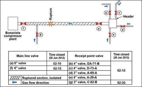
- At 0210, the Bonavista main line valve near the header at the upstream end of the Bonavista pipeline segment was closed by Bonavista personnel (see (a) on Figure 5). Furthermore, the 4 receipt pointsFootnote 7 in the header area were closed (see (b), (c), (d) and (e) on Figure 5). This isolated the Bonavista pipeline upstream of the rupture.
- At 0215, the isolation valve at the KP 17.11 receipt point on the Nig Creek pipeline was manually closed by Westcoast personnel (see (d) on Figure 4).
- At 0215, the Bonavista main line valve at the downstream end of the pipeline near its compressor plant was closed by Bonavista personnel (see (f) on Figure 5).
- At 0230, the isolation valve at the Bonavista receipt point "C-82-B" was closed by Bonavista personnel (see (g) on Figure 5). This completed the isolation of the ruptured section of the Bonavista pipeline.
- At 0245, the Bonavista pipeline was depressurized to 0 kPa.
- At 0350, Westcoast personnel began the process of depressurizing the ruptured segment of the Nig Creek pipeline through a flare system.
- At 0410, the isolation valve at the KP 9.41 receipt point on the Nig Creek pipeline was closed by Westcoast personnel (see (e) on Figure 4). This completed the isolation of the ruptured section of the Nig Creek pipeline.
- Between 0417 and 0435, isolation valves at 3 receipt points located between KP 25.8 and KP 30.87 along the Nig Creek pipeline were manually closed by Westcoast personnel (see (f), (g) and (h) on Figure 4..
- At 0430, the ruptured segment of the Nig Creek pipeline was depressurized to 0 kPa.
- Following the isolation of the ruptured sections of the Nig Creek pipeline and the Bonavista pipeline, the fire was managed by allowing product left within the isolated damaged pipeline sections to burn off. The pipeline fire self-extinguished at 1630 on 29 June 2012.
- The fire in the adjacent forested area was supressed by dropping water from a nearby creek using a helicopter equipped with a water bucket. Westcoast requested and received assistance from the British Columbia Ministry of Forests, Lands and Natural Resource Operations. The forest fire was extinguished at 1700 on 30 June 2012.
- On 14 July 2012, the Nig Creek pipeline and the Bonavista pipeline were repaired by welding in place pre-tested sections of pipe. The crater at the site was then backfilled with soil.
- On 15 July 2012, the Bonavista pipeline was returned to normal service.
- On 21 September 2012, following a successful hydrostatic test of the entire pipeline at a minimum test pressure of 125% MOP, the Nig Creek pipeline was returned to normal service.
Site examination
A detailed site Examination was performed by the TSB following the occurrence. The following was observed:
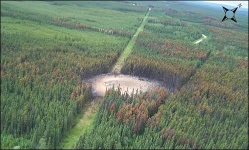
- Approximately 1.6 hectares was burned (see Photo 1).
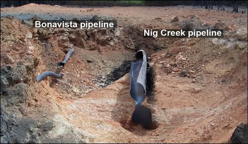
- A large crater (that is, 17 m long, 7.6 m wide and 1.1 m deep) was formed. A 6 m-long piece of pipe had separated from the Nig Creek pipeline and was ejected approximately 20 m to the northeast along with other debris (see Photo 2).
- The remaining damaged section of the Nig Creek pipe, as well as the entire damaged section of the Bonavista pipe, was found within the crater.
- No ground water was present.
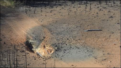
Within the crater, the exterior coating of the Nig Creek pipeline (that is, asphalt enamel) and the exterior coating of the Bonavista pipeline (that is, extruded polyethylene) were completely destroyed by the fire (see Photo 3).
- Upstream and downstream of the failed sections, the exterior coating of both pipelines were in good condition.
- Approximately 17 m of the Nig Creek pipeline and 9 m of the Bonavista pipeline were damaged during the pipeline ruptures and resulting fire.
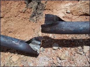
- The Nig Creek pipeline had ruptured along its longitudinal seam weld (see Photo 4).
- The Bonavista pipeline's rupture exhibited a thin-lipped "fish mouth" feature, which is characteristic of a pipe failure due to overheating (see Photo 5).
- The environmental impact consisted primarily of fire damage to the adjacent forested land and loss of top soil within the crater.
The damaged sections of both pipelines, along with short intact sections of pipe upstream and downstream of the damaged area were cut outFootnote 8 and sent to the Acuren Group Inc. laboratory in Richmond, British Columbia, for further analysis.
Laboratory analysis of the failed pipes
The laboratory analysis of the failed sections of the Nig Creek pipeline included visual examination, magnetic particle inspection, coating testing, chemical, metallography, mechanical testing and hardness testing. The following was determined:
- The pipeline rupture was the result of a pre-existing hook crackFootnote 9 that caused a fracture along the electric resistance welded longitudinal seam of a pipe joint (see Photo 6).
- The rupture likely initiated in the downstream section and propagated to the ejected pipe section.
- The hook cracks had been created in the original electric resistance weld when the pipe was manufactured.
- It was not possible to identify a growth mechanism for the hook crack.
- The external coating on the ejected pipe was missing as a result of fire damage.
- The external coating on the upstream and downstream pipe sections, which were outside the fire zone, as well as some partially melted coating closer to the fire, exhibited good adhesion to the pipe.
- Visual examination and magnetic particle inspection of the pipe sections found no evidence of mechanical damage.
- There was no evidence of environmental or service-related degradation (for example, corrosion, thinning or environmental cracking).
The laboratory analysis of the failed Bonavista pipeline segments included visual examination, chemical analysis metallography and hardness testing. It was determined that:
- The rupture of the Bonavista pipeline was the result of overheating due to fire impingement, which had lowered its yield strength, reducing its ability to withstand the internal pressure.
Regulatory requirements for pipeline integrity management
Section 40 of the NEB Onshore Pipeline Regulations, 1999, SOR/99-294 (OPR-99) requires a co MPany to develop a pipeline integrity management program. The OPR-99 also adopt by reference the latest edition of the CSA Z662Footnote 10 standard, which includes provisions pertaining to the content of pipeline integrity management programs.
While the NEB, in its Guidance Notes for the Onshore Pipeline Regulations, provides direction in developing a pipeline integrity management program, pipeline co MPanies have flexibility and discretion to develop the content of their pipeline integrity management program.
It is the NEB's expectation that regulated co MPanies, as part of their pipeline integrity management program, proactively identify and continually monitor the specific hazards associated with their pipelines (regardless of vintage), and i mmediately update their pipeline integrity management program when new hazards are identified. The effectiveness of each regulated company's program is monitored by the NEB on an ongoing basis with the goal of ensuring that pipelines are suitable for continued safe, reliable and environmentally responsible service.
The effect of these provisions is that regulated pipeline co MPanies develop pipeline integrity management programs tailored to their specific circumstances, and initiate corrective action for defects that are known to exist or are found to exceed criteria established by CSA Z662.
Westcoast's pipeline integrity management program
Westcoast's pipeline Integrity Management Program (IMP) for its sour gathering lines in effect at the time of the occurrence includes an in-line inspection program and a corrosion monitoring and control program.
The in-line inspection program includes:
- regular inspections using in-line deformation tools;
- in-line inspections using high-resolution MFL tools;
- an annual review of planned in-line inspections, where adjustments are made based on the results of previous in-line inspections, as applicable;
- the excavation and repair of all potential defects identified by the in-line inspections; and
- the inspection and repair of all excavated pipe for evidence of stress corrosion cracking.
All inspection and excavation information, including repair details, is entered in Westcoast's Geographic Information System (GIS).
The corrosion monitoring and control program includes:
- monthly CP rectifier readings;
- annual pipe-to-soil surveys;
- inhibition of the pipelines to minimize internal corrosion (that is, by continuous injection or batching of chemical inhibitors);
- regular pigging of the pipelines to maintain flow efficiency and prevent the formation of hydrates (that is, by removing liquids, acidic fluids and electrolytes); and
- monitoring of the effectiveness of the inhibitor and pigging programs (that is, by using weight loss coupons and hydrogen probes).
Analysis
The accident
The Nig Creek pipeline ruptured at KP 1.93 when the load-bearing capacity of the pipe was reduced due to a pre-existing hook crack along the electric resistance welded longitudinal seam, which grew by a time-dependent mechanism and led to the explosion and fire.
In the 14 hours (approx.) prior to the rupture, the pipeline experienced a gradual pressure increase from 4100 kPa to 6656 kPa. The pressure increase was due to the accumulating sour gas in the Nig Creek pipeline when the McMahon plant was temporarily shut down. Although the pressure increase stayed below the pipeline's authorized MOP of 6895 kPa, the elevated pressure was sufficient to rupture the pipe along the longitudinal seam starting at the location of the pre-existing hook crack. The pre-existing hook crack did not fail earlier because it had not reached a critical size in relation to the operating stresses it was subjected to during the past 5 decades of operation. While the crack growth mechanism could not be confirmed, it is likely that the hook crack was the initiating crack, which had been growing over an undetermined period of time.
The crater caused by the Nig Creek pipeline explosion exposed the Bonavista pipeline. While this pipeline was not initially damaged by the explosion, it was impinged by the resulting fire. Over about 25 minutes, the Bonavista pipeline overheated locally, which lowered the pipe's strength and reduced its ability to withstand the internal pressure. This led to local swelling of the pipe and yielding of the steel until rupture. The sour gas escaping from the ruptured Bonavista pipeline ignited and contributed to feeding the fire.
Notification of pipeline rupture
The first indication of an anomaly on the Nig Creek pipeline occurred approximately 9 minutes following the line rupture, when the Westcoast SCADA system reported low-pressure alarms originating from sensors within the BS-9 station. The alarms were triggered when the transient gas decompression wave, created by the rupture event and propagating upstream in the ruptured pipe section, started reaching the BS-9 station sensors. These alarms were interspersed among other gathering system alarms displayed on the SCADA system's alarm screen and were all assigned a "Medium Alarm" priority. This made these alarms hard to distinguish from the other concurrent alarms being displayed on the SCADA alarm screen, many of which were also assigned "Medium Alarm" priority.
Furthermore, the descriptions of these alarms led the gas controller to initially interpret them to be related to a change in status at the BS-9 station rather than an anomaly on the Nig Creek pipeline. In addition, while the Westcoast controller was monitoring several systems that were operating near their maximum operating pressure, he received simultaneous telephone calls from gas producers requesting to come back on line.
The concurrent alarms, their priorities and descriptions, as well as the need to respond to a number of operational telephone calls, contributed to a delay of about 16 minutes between the reporting of the alarms by the SCADA system and their acknowledgement.
As a result of multiple inputs and alarms relating to other events, the specific alarms that followed the rupture were not responded to in a timely manner. If excessive workload of system controllers is not properly managed, there is a risk that emergency response will be delayed.
Testing of the Nig Creek pipeline
In 1960, when the Nig Creek pipeline was initially subjected to the post-construction pneumatic test, several pipe joint failures occurred along the longitudinal seam. Seam failures on that vintage of pipe (that is, welded using low-frequency electric resistance) were generally caused by defects such as lack of fusion or hook cracks. For older pipe sections that were welded using a low-frequency electric resistance welding process, there is an increased likelihood for the presence of seam defects (for example, lack of fusion or hook cracks), which increases the risk of in-service failures.
In this occurrence, the pre-existing hook crack remained undetected after surviving a pneumatic test in 1960 and multiple hydrostatic tests in 1961. The successful hydrostatic tests in 1961 were not sufficient to address the development of a time-dependent growth mechanism associated with the original longitudinal seam defects that might later threaten the integrity of the pipeline while in operation.
Pipeline integrity management program
The overall objective of a pipeline IMP is to ensure that hazards and threats affecting the safe operation of the pipeline are effectively identified and mitigated to ensure suitability of the pipeline system for continued service.
Westcoast’s IMP for the Nig Creek pipeline in effect at the time of the occurrence recognized that internal corrosion and external corrosion are integrity hazards. These hazards were managed through the use of corrosion protection and control systems combined with periodic internal inspections using MFL in-line inspection tools and targeted excavations and repairs.
Westcoast’s IMP for the Nig Creek pipeline in effect at the time of the occurrence did not consider cracks and crack-like defects to be a significant hazard to the integrity of the Nig Creek pipeline. Westcoast was of the view that the pipeline’s risk exposure to these types of defects was low, given the pipeline’s physical characteristics, operating environment, inspection and test data and the absence of any low-frequency electric resistance weld-related leaks or failures in this or similar pipe over more than 50 years of continuous service. As such, there was no specific crack and crack-like defect detection and mitigation program in place for the Nig Creek pipeline, and the Nig Creek pipeline had not been subjected to a hydrostatic retest since 1961.
Periodic hydrostatic testing has historically been used by pipeline co MPanies to confirm the integrity of pipeline sections from potential time-dependent threats including corrosion, cracking and manufacturing defects. While hydrostatic testing can demonstrate that, at a specific point in time, the pipeline is capable of withstanding a specific pressure, there are situations where hydrostatic testing can potentially lead to the introduction of additional unwanted failure mechanisms such as the initiation, re-initiation or growth of sub-critical sharp flaws that were otherwise dormant. Other limitations of hydrostatic testing include its inability to detect certain types of sub-critical defects that would only fail at a pressure greater than the pressure they were subjected to during the test, and the potential to compromise the internal corrosion protection of sour gas pipelines by disrupting the pipelines’ internal iron-sulfide surface film.
The Nig Creek pipeline’s IMP included the use of high-resolution MFL in-line inspection tools to mitigate corrosion-related threats. While this type of in-line inspection tool has been successful in identifying corrosion zones, it is not designed to detect cracks and crack-like defects in the pipe.
In-line inspection tools for detecting cracks have been around for many years, and recent advancements in technology have improved the usability of these tools in gas pipelines and enhanced their crack-like defect detection capabilities. In recent years, some of these tools have started to demonstrate their ability to provide improved integrity-related information when co MPared to a point-in-time hydrostatic pressure test. It is expected that such tools will continue to be further developed and improved with the support of a coordinated effort between pipeline co MPanies, tool vendors, service providers, equipment manufacturers and other organizations
However, prior to using crack detection in-line inspection tools, the type of tool and technology being considered should be validated to ensure that it is appropriate for the cracking mechanism that is suspected to affect a specific pipeline, as not all tools and technologies are capable of reliably detecting and discriminating all types of cracks or crack-like features. In those instances where such tools are not readily available or suitable to reliably detect defects of interest, the effective management of cracks and crack-like defects in operating pipelines continues to require complementary measures, including but not limited to periodic hydrostatic testing.
Findings
Findings as to causes and contributing factors
- The Nig Creek pipeline ruptured at KP 1.93 when the load-bearing capacity of the pipe was reduced due to a pre-existing hook crack along the electric resistance welded longitudinal seam, which grew by a time-dependent mechanism and led to the explosion and fire.
- Prior to the rupture, the pipeline experienced a gradual pressure increase due to the accumulating sour gas in the Nig Creek pipeline when the McMahon plant was temporarily shut down.
- The elevated pressure was sufficient to rupture the pipe along the longitudinal seam starting at the location of the pre-existing hook crack.
- The pre-existing hook crack had likely been growing over an undetermined period of time.
- The Integrity Management Program (IMP) did not consider cracks and crack-like defects to be a significant potential hazard to the integrity of the Nig Creek pipeline.
Findings as to risk
- For older pipe sections that were welded using a low-frequency electric resistance welding process, there is an increased likelihood for the presence of seam defects (for example, lack of fusion or hook cracks), which increases the risk of in-service failures.
- As a result of multiple inputs and alarms relating to other events, the specific alarms that followed the rupture were not responded to in a timely manner. If excessive workload of system controllers is not properly managed, there is a risk that emergency response will be delayed.
Other findings
- While in-line inspection tools using magnetic flux leakage technology have been successful in identifying corrosion zones, they are not designed to detect cracks in the pipe.
- In-line inspection tools for detecting cracks have been around for many years, and recent advancements in technology have improved the usability of these tools in gas pipelines and enhanced their crack-like defect detection capabilities.
- In instances where crack-detection in-line inspection tools are not readily available or suitable to reliably detect defects of interest, the effective management of cracks and crack-like defects in operating pipelines continues to require complementary measures, including but not limited to periodic hydrostatic testing.
- The Bonavista pipeline overheated locally due to the pipeline cover being removed by the explosion of the Nig Creek pipeline and the ensuing fire. The heat lowered the Bonavista pipe’s strength and reduced its ability to withstand the internal pressure, leading to local swelling of the pipe and yielding of the steel until rupture.
Safety action
Safety action taken
Following the occurrence, the National Energy Board (NEB) directed Westcoast to conduct the necessary integrity assessments and repairs prior to seeking approval to return the pipeline into service.
The following safety actions were taken by Westcoast:
- A hydrostatic test at a minimum test pressure of 125% of maximum operating pressure was conducted in August 2012 on the entire Nig Creek pipeline. There were no pipe failures during the hydrostatic test.
- In October 2012, the Nig Creek pipeline’s ongoing monitoring and verification plan for the pipeline’s fitness for service was filed with the NEB.
- Additional metallurgical analysis of other pipe removed from the Nig Creek pipeline during the return-to-service hydrostatic test was co mmissioned.
- An axial flaw detection in-line inspection of the Nig Creek pipeline is scheduled for May 2013.
- A control room management review, including a review of supervisory control and data acquisition (SCADA) alarm naming, grouping and prioritization, has been initiated. It is anticipated that this will result in changes in alarm priorities and alarm naming as well as a reduction in the number of alarms a controller must manage.
This report concludes the Transportation Safety Board's investigation into this occurrence. Consequently, the Board authorized the release of this report on 29 May 2013. It was officially released on 04 June 2013.


