West Wind Aviation L.P.
Avions de Transport Régional ATR 42-320, C-GWEA
Fond-du-Lac, Saskatchewan
The Transportation Safety Board of Canada (TSB) investigated this occurrence for the purpose of advancing transportation safety. It is not the function of the Board to assign fault or determine civil or criminal liability. This report is not created for use in the context of legal, disciplinary or other proceedings. See Ownership and use of content. Masculine pronouns and position titles may be used to signify all genders to comply with the Canadian Transportation Accident Investigation and Safety Board Act (S.C. 1989, c. 3).
Executive summary
On 13 december 2017, an Avions de Transport Régional ATR 42-320 aircraft (registration C-GWEA, serial number 240), operated by West Wind Aviation L.P. (West Wind), was scheduled for a series of instrument flight rules flights from Saskatoon through northern Saskatchewan as flight WEW282.
When the flight crew and dispatcher held a briefing for the day’s flights, they became aware of forecast icing along the route of flight. Although both the flight crew and the dispatcher were aware of the forecast ground icing, the decision was made to continue with the day’s planned route to several remote airports that had insufficient de-icing facilities.
The aircraft flew from Saskatoon/John G. Diefenbaker International (CYXE) to Prince Albert (Glass Field) Airport (CYPA) without difficulty, and, after a stop of about 1 hour, proceeded on toward Fond-du-Lac Airport (CZFD). On approach to Fond-du-Lac Airport, the aircraft encountered some in-flight icing, and the crew activated the aircraft’s anti-icing and de-icing systems.
Although the aircraft’s ice protection systems were activated, the aircraft’s de-icing boots were not designed to shed all of the ice that can accumulate, and the anti-icing systems did not prevent ice accumulation on unprotected surfaces. As a result, some residual ice began to accumulate on the aircraft.
The flight crew were aware of the ice; however, there were no handling anomalies noted during the approach. Consequently, they likely did not assess that the residual ice was severe enough to have a significant effect on aircraft performance. The crew continued the approach and landed at Fond-du-Lac Airport at 1724 Central Standard Time.
According to post-accident analysis of the data from the flight data recorder, the aircraft’s drag and lift performance was degraded by 28% and 10%, respectively, shortly before landing at Fond-du-Lac Airport. This indicated that the aircraft had significant residual ice adhering to its structure upon arrival. However, this data was not available to the flight crew at the time of landing.
The aircraft was on the ground at Fond-du-Lac Airport for approximately 48 minutes. The next flight was destined for Stony Rapids Airport (CYSF), Saskatchewan, with 3 crew members (2 pilots and 1 flight attendant) and 22 passengers on board.
Although there was no observable precipitation or fog while the aircraft was on the ground, weather conditions were conducive to ice or frost formation. This, combined with the residual mixed ice on the aircraft, which acted as nucleation sites that allowed the formation of ice crystals, resulted in the formation of additional ice or frost on the aircraft’s critical surfaces.
Once the passengers had boarded the aircraft, the First officer completed an external inspection of the aircraft. However, because the available inspection equipment was inadequate, the First officer’s ice inspection consisted only of walking around the aircraft and looking at the left wing from the top of the stairs at the left rear door, without the use of a flashlight on the dimly lit apron.

Although he was unaware of the full extent of the ice and the ongoing accretion, the First officer did inform the captain that there was some ice on the aircraft. The captain did not inspect the aircraft himself, nor did he attempt to have it de-iced; rather, he and the First officer continued with departure preparations.
Company departures from remote airports, such as Fond-du-Lac, with some amount of surface contamination on the aircraft’s critical surfaces had become common practice, in part due to the inadequacy of de-icing equipment or services at these locations. The past success of these adaptations resulted in this unsafe practice becoming normalized and this normalization influenced the flight crew’s decision to depart.
Although the flight crew were aware of icing on the aircraft’s critical surfaces, they decided that the occurrence departure could be accomplished safely. Their decision to continue with the original plan to depart was influenced by continuation bias, as they perceived the initial and sustained cues that supported their plan as more compelling than the later cues that suggested another course of action. At 1812 Central Standard Time, in the hours of darkness, the aircraft began its take-off roll on Runway 28, and, 30 seconds later, it was airborne.
As a result of the ice that remained on the aircraft following the approach and the additional ice that had accreted during the ground stop, the aircraft’s drag was increased by 58% and its lift was decreased by 25% during the takeoff.
Despite this degraded performance, the aircraft initially climbed; however, immediately after liftoff, the aircraft began to roll to the left without any pilot input. This roll was as a result of asymmetric lift distribution due to uneven ice contamination on the aircraft.
Following the uncommanded roll, the captain reacted as if the aircraft was an uncontaminated ATR 42, with the expectation of normal handling qualities and dynamic response characteristics; however, due to the contamination, the aircraft had diminished roll damping resulting in unexpected handling qualities and dynamic response. Although the investigation determined that the ailerons had sufficient roll control authority to counteract the asymmetric lift, due to the unexpected handling qualities and dynamic response, the roll disturbance developed into an oscillation with growing magnitude and control in the roll axis was lost.
This loss of control in the roll axis, which corresponds with the known risks associated with taking off with ice contamination, ultimately led to the aircraft colliding with terrain 17 seconds after takeoff.
The aircraft collided with the ground in a relatively level pitch, with a bank angle of 30° left. As a result of the sudden vertical deceleration upon contact with the ground, the aircraft suffered significant damage, which varied in severity at different locations on the aircraft due to impact angle and variability in structural design.
Neither current design standards for transport category aircraft, nor those in effect at the time the ATR 42 was certified, specify minimum loads that a fuselage structure must be able to tolerate and remain survivable, or minimum loads for fuselage impact energy absorption. As a result, the ATR 42 was not designed with such crashworthiness parameters in mind.
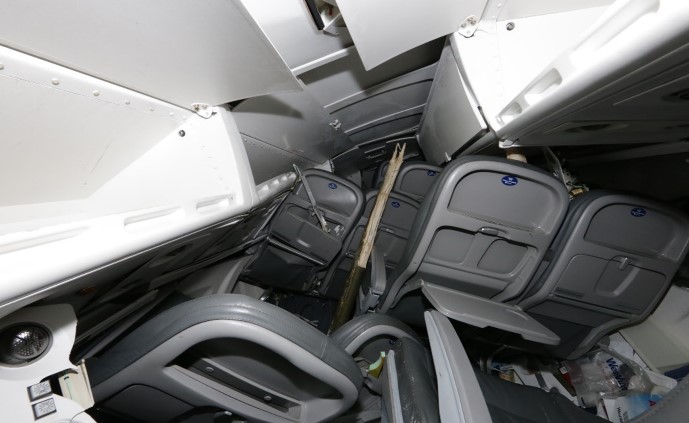
The main landing gear at the bottom of the centre fuselage section was rigid, and, on impact, did not absorb or attenuate much of the load. The impact-induced acceleration was not attenuated because the landing gear housing did not deform. This unattenuated acceleration resulted in a large inertial load from the wing, causing the wing support structure to fail and the wing to collapse into the cabin.
The reduced survivable space between the floor above the main landing gear and the collapsed upper fuselage caused crushing injuries, such as major head, body, and leg trauma, to passengers in the middle-forward left section of the aircraft. Of the 3 passengers in this area, 2 experienced, serious life-changing injuries, and 1 passenger subsequently died.
The collapse of part of the floor structure compromised the restraint systems, limiting the protection afforded to the aircraft occupants when they were experiencing vertical, longitudinal, and lateral forces. This resulted in serious velocity-related injuries and impeded their ability to take post-crash survival actions in a timely manner. Unaware of the danger, most passengers in this occurrence did not brace for impact. Because their torsos were unrestrained, they received injuries consistent with jackknifing and flailing, such as hitting the seat in front of them.
As a result of unapproved repairs, the flight attendant seat failed on impact, resulting in injuries that impeded her ability to perform evacuation and survival actions in a timely manner.
Although the TSB has previously recommended the development and use of child restraints aboard commercial aircraft, planned regulations have yet to be implemented by Transport Canada. As a result, the occurrence aircraft was not equipped with these devices, and an infant passenger who was unrestrained received flailing and crushing injuries during the accident sequence.
By the time the aircraft came to a rest, all occupants had received injuries. Passengers began to call for help within minutes of the impact, using their cell phones. Numerous people from the nearby community received the messages and quickly set out to help.
The passengers and crew began to evacuate, but they experienced significant difficulties as a result of the aircraft damage. It took approximately 20 minutes for the first 17 passengers to evacuate, and the remaining passengers much longer; it took as long as 3 hours to extricate 1 passenger, who required rescuer assistance.
As a result of the accident, 9 passengers and 1 crew member received serious injuries, and the remaining 13 passengers and 2 crew members received minor injuries. One of the passengers who had received serious injuries died 12 days after the accident.
There was no post-impact fire, and the emergency locator activated on impact.
Early in this investigation, it became clear that more information was needed to determine whether the underlying factors identified in this occurrence were present elsewhere in the Canadian commercial aviation industry.
To assess the risks involved with winter operations at remote northern airports, and specifically the risk posed by aircraft taking off with frost, ice, or snow adhering to critical surfaces, the TSB conducted an online survey of pilots who were directly exposed to operations at remote airports throughout Canada.
The responses received to several questions showed that operations at these remote airports were routinely affected by the unavailability and inadequacy of equipment to inspect, de-ice, or anti-ice aircraft.
The combined probability and severity of this safety deficiency poses a high risk to transportation safety. The risk likely varies from airport to airport, depending somewhat on the frequency of operations; however, identifying high-risk locations for immediate mitigation can quickly reduce the likelihood of aircraft taking off with frost, ice, or snow adhering to any critical surface at those locations.
Transport Canada, air operators, and airport authorities have the capacity to identify high‑risk locations, analyze them for hazards and risks, and take mitigating action.
Therefore, in December 2018, the Board recommended that
the Department of Transport collaborate with air operators and airport authorities to identify locations where there is inadequate de-icing and anti-icing equipment and take urgent action to ensure that the proper equipment is available to reduce the likelihood of aircraft taking off with contaminated critical surfaces.
TSB Recommendation A18-02
The most notable information received from the survey showed that, in the past 5 years, 74% of pilots had seen aircraft take off with contaminated surfaces, in contravention of regulations and the clean aircraft concept. This majority indicates that the issue is systemic, rather than isolated to a small number of operators or a select few locations.
There are many defences in place to ensure the clean aircraft concept is followed, such as regulations, company operating manuals, and standard operating procedures. However, all of these defences rely singularly on flight crew compliance. As seen in this occurrence, when a single-point compliance adaptation is made, aircraft may depart with contaminated surfaces, despite several adequate administrative defences in place.
To mitigate this hazard, Transport Canada and air operators must take urgent action to ensure better compliance.
Accidents related to contaminated aircraft will continue to occur until the industry and the regulator approach the issue as systemic and take action to eliminate underlying factors that can negatively affect pilot compliance.
Therefore, in December 2018, the Board recommended that
the Department of Transport and air operators take action to increase compliance with Canadian Aviation Regulations subsection 602.11(2) and reduce the likelihood of aircraft taking off with contaminated critical surfaces.
TSB Recommendation A18-03
When West Wind commenced operations into CZFD in 2014, no effective risk controls were in place to mitigate the potential hazard of ground icing. Transportation companies have a responsibility to manage safety risks in their operations; however, compliance with regulations can provide only a baseline level of safety. When implemented properly, SMS enables companies to manage risk effectively and make operations safer. For SMS to be effective, it must be supported by a positive safety culture. If a company’s safety culture tolerates unsafe practices, there is a risk that these practices will continue and become a company norm.
Safety management is an issue on the TSB’s Watchlist 2020, which identifies the key safety issues that need to be addressed to make Canada’s transportation system even safer.
The investigation also revealed a number of instances in which Transport Canada’s surveillance policies and procedures were inconsistently applied to the oversight of West Wind. This is not the first time that such inconsistencies in Transport Canada’s oversight of commercial aviation in Canada have been identified. As detailed in the findings of several TSB investigations, there have been a number of past examples where Transport Canada has been slow to either identify or to rectify unsafe conditions at an operator. Transport Canada’s inconsistent application of its own policies and procedures for the 2016 assessment of West Wind and subsequent post-assessment corrective action plan verifications, as well as the ad hoc approach to enhanced monitoring, resulted in ineffective oversight of an operator that had a history of system-level (i.e., safety management system [SMS]) and systemic (e.g., operational control) non-compliance issues.
If the application of Transport Canada’s surveillance policies and procedures is inconsistent, there is a risk that resulting oversight will be ineffective at ensuring that operators are able to effectively manage the safety of their operations.
Regulatory surveillance is also an item on the TSB’s Watchlist 2020.
1.0 Factual information
1.1 History of the flight
1.1.1 General
On 13 December 2017, the West Wind Aviation L.P. (West Wind) Avions de Transport Régional (ATR) 42-320 aircraft (registration C-GWEA, serial number 240), was conducting West Wind flight 282 (WEW282), which consisted of a series of instrument flight rules flights through northern Saskatchewan.
WEW282 originated from Saskatoon/John G. Diefenbaker International Airport (CYXE), and was scheduled to make stops at Prince Albert (Glass Field) Airport (CYPA), Fond-du-Lac Airport (CZFD), Stony Rapids Airport (CYSF), Wollaston Lake Airport (CZWL), Points North Landing Airport (CYNL), and back to CYPA before terminating at CYXE.
WEW282 was being operated under Subpart 705 of the Canadian Aviation Regulations (CARs).Footnote 2 The flight was chartered by Transwest Air, a West Wind subsidiary, to transport overflow passengers and cargo from a scheduled flight operated by Transwest Air that was flying the same route ahead of WEW282.
1.1.2 Pre-flight planning and dispatch
At 1215,Footnote 3 a West Wind dispatcher began organizing the WEW282 operational flight plans (OFPs) for all 7 segments of the planned flight. WEW282 was planned to depart from CYXE at 1430 with no passengers on board and a fuel load of 8200 pounds. The plan was for WEW282 to complete the scheduled route without taking on additional fuel at any stops en route. At 1225, the OFP for the occurrence flight was completed.
The WEW282 crew, which comprised 2 pilots and 1 flight attendant (FA), reported for duty at the West Wind hangar at CYXE at approximately 1330. The FA proceeded with her duties to get the aircraft cabin ready for the flight, while the captain and First officer (FO) met with the dispatcher for a pre-flight briefing.
The briefing consisted of all of the items required for the flight,Footnote 4 including the current weather; aerodrome and area forecasts for takeoff, en route, destination, alternate and the return trip segments; and the forecast icing in the area of operations.
1.1.3 Saskatoon to Fond-du-Lac
For the departure from CYXE, the captain was seated in the left seat and was the pilot flying (PF). The FO, who was also captain-qualified, was seated in the right seat and was the pilot not flying (PNF). The pilots were planning to switch seats and flying duties for the rest of the day after landing at CYSF.
WEW282 departed CYXE at 1406 and, following an uneventful flight, arrived at CYPA at 1442. WEW282 departed CYPA at 1532, with 15 passengers on board, and was cleared by air traffic control (ATC) to fly direct to CZFD at flight level (FL) 220.Footnote 5 The takeoff, climb, and cruise segments of the flight were uneventful.
At 1657, WEW282 was in cruise flight approximately 86 nautical miles (NM) south of CZFD when ATC issued a clearance to depart controlled airspace and provided the crew with the 1654 automated weather observation system (AWOS) aerodrome routine meteorological report (METAR) for CYSF (see section 1.7.2.1 Aerodrome routine meteorological reports).
At 1658, the crew of a Saab 340 operating as Transwest Air flight 280 (TW280) informed WEW282 that TW280 was also inbound to CZFD and was approximately 6 minutes ahead. Shortly thereafter, the crew of another aircraft, a Beechcraft 1900 operating as WEW660, announced that they were also inbound to CZFD and were ahead of TW280.
At 1702 civil twilight ended, and night began. Four minutes later, the WEW282 flight crew briefed for the RNAV (GNSS)Footnote 6 instrument approach procedure for landing on Runway 28. At 1710, the crew of TW280 broadcasted that they were 6 miles to the south of the airport and had the runway in sight.
At 1713:15, while WEW282 was descending through 8100 feet,Footnote 7 it began to encounter in-flight icing. The captain instructed the FO to increase ice protection from Level 1 to Level 2 (see section 1.6.2 Aircraft ice protection systems), and the aircraft’s torque was increased from less than 5% to 50%.
Thirty seconds later, while the aircraft was descending through 7600 feet, the master caution single chime sounded and the CAUTION and ICINGFootnote 8 alert lights illuminated, indicating that ice accretion was detected on the ice probe. Five seconds after icing conditions were detected by the ice detector, the captain instructed the FO to engage Level 3 ice protection (pneumatic airframe de-icing systems).
Three minutes after the probe initially detected icing conditions, as the aircraft was descending through 4700 feet, the torque was reduced to 35% and the aircraft performance monitoring (APM)Footnote 9 system’s DEG PERF light illuminated.Footnote 10 The ICING light remained illuminated.
At 1719:50, as the aircraft was established on the extended runway centreline, the APM’s INC SPD (increase speed) flashing light illuminated.Footnote 11 The airspeed was 156 knots indicated airspeed (KIAS), and the descent rate was approximately 250 fpm. Shortly thereafter, the torque increased to 55% and airspeed increased to 167 KIAS. Fourteen seconds after the initial illumination, the INC SPD light extinguished; however, the APM’s DEG PERF light remained illuminated.
At 1720:43, while the aircraft was descending through 3000 feet, the flaps were set to 15° and the landing gear was extended. At the same time, the APM’s DEG PERF light extinguished.Footnote 12 The descent rate increased to 750 fpm.
Forty seconds later, while the aircraft was descending through 2900 feet, the ICING light also extinguished and remained off for the remainder of the flight, indicating that ice was no longer accreting on the probe. Flaps were extended to 30° at 1721:57.
At 1722:23, while the aircraft was descending through 2100 feet, both pilots acquired visual reference with the runway, and 1 minute later, after letting the de-icing system run through 1 more cycle, the crew returned ice protection to Level 1. Following this selection, the crew briefly discussed the presence of residual ice on the aircraft.
While the aircraft was descending through 1450 feet, the captain disengaged the autopilot. No anomalies were noted during the remainder of the approach, and the aircraft landed on Runway 28 at 1724:44.
1.1.4 On the ground at Fond-du-Lac
At 1726:19, WEW282 cleared the runway and taxied to the apron. WEW660 already had its engines running and was ready to start taxiing for departure, which it did immediately after WEW282 taxied past, and subsequently departed from Runway 10.
At 1727:42, once the aircraft was stopped on the apron, the flight crew of WEW282 engaged the parking brake, shut down the left engine, and activated the propeller brakeFootnote 13 for the right engine. Eight of the 15 passengers on board were destined for Fond-du-Lac and disembarked; the other 7 were destined for later stops and remained on board.
The flight crew then left the cockpit to assist with loading. At about 1745, loading was completed, and the captain returned to the cockpit and began programming the next flight into the flight management system (FMS) and calculating the weight and balance. The FO proceeded to the airport terminal building to escort passengers to the aircraft.
At 1754, TW280 taxied away from the apron and subsequently departed from Runway 28. The FO of WEW282 then escorted 15 passengers to the aircraft; these passengers included 1 child and 1 passenger in a wheelchair.
Once the passengers had boarded the aircraft, the FO walked around the aircraft to conduct a visual external inspection. Although this inspection was accomplished during the hours of darkness on the dimly lit apron and without the use of a flashlight, the FO observed contamination on the nose of the aircraft and some residual ice on the leading edges of the wings, engine intakes, and the vertical stabilizer. The FO completed the external inspection by visually examining the left wing from the top of the airstair door on the left side of the rear cabin.
By 1803:40, the FO had returned to the cockpit. He told the captain that he noticed that there was more ice outside than he had originally thought. The captain, who was working on departure calculations, acknowledged, and then the FO pointed out that ice was also sticking to the power lines. The captain again acknowledged, and, referring to the ice on the power lines, the FO said that the ice was on the aircraft as well. The captain responded in a way that indicated he was not concerned. The discussion lasted for 9 seconds before the captain returned to his calculations.
Within 15 seconds from the beginning of the icing discussion, the captain told the FO that they had 7 more passengers than anticipated, and instructed the FO to begin the before-start checklist.
1.1.5 Taxiing for departure from Fond-du-Lac
The proposed flight plan for WEW282 for the 42 NM eastbound flight from CZFD to CYSF was to fly direct at an altitude of 7000 feet.

At 1805, while the before-start check was being conducted, the captain briefed the normal speeds on the 35 000-pound take-off card (Figure 1) because the aircraft was heavier than originally planned. The crew then set the speed bugs as per the normal (non-icing) numbers on the card: V1/VR 100 KIAS,Footnote 14 V2 106 KIAS,Footnote 15 VLO 127 KIAS,Footnote 16 and VLO icing 147 KIAS.Footnote 17
By 1806:35, the right engine propeller brake was released, the left engine was started, and the aircraft began to taxi for Runway 28.
The taxi and backtrack for Runway 28 was slightly longer than that for Runway 10, and the takeoff was in the opposite direction of the planned flight. However, the captain discussed that although the winds were light, they were favouring Runway 28, and because the aircraft was heavier than originally planned, it would be better to use the into-wind runway.
The FO responded that he agreed and that, with the amount of ice that was on the aircraft, he would rather have a couple of knots of headwind.
As part of the taxi checks, at 1807:45 the captain conducted the take-off briefing. During this briefing, the captain mentioned the known potential threat of departing toward an area of darkness, and how they would mitigate this.
The captain called for before-takeoff checks at 1809:07. In response to the checklist item regarding anti-ice, the captain decided that Level 1 icing protection was sufficient for takeoff.
At 1810:48, the aircraft was stopped on the threshold of Runway 28, in position for takeoff. Ten seconds later, while completing the before-takeoff checks, the captain visually observed the left spoiler from the cockpit window and acknowledged having it in sight. Shortly afterward, the FO visually observed the right spoiler from the cockpit window and reported that he had it in sight, but just barely. This spoiler check is considered the last-chance inspection to check for surface contamination before takeoff.
Between 1811:33 and 1811:58, the crew completed the line-up checks and then made a traffic advisory broadcast on the aerodrome traffic frequency to report that they were rolling for departure from Runway 28. This was the last radio transmission from the WEW282 flight crew before the occurrence.
1.1.6 Takeoff from Fond-du-Lac
At 1812:01, the captain began to increase power, and WEW282 commenced the take-off roll. As instructed by the captain, the FO set the power to the appropriate take-off setting and, at 1812:18, announced that the airspeed was increasing through 70 KIAS.
As the aircraft reached a speed of 100 KIAS at 18:12:29, the FO announced that the speed had reached V1 and VR, and the captain began to rotate the aircraft to 10° of nose-up pitch.
The aircraft lifted off the runway at 1812:31, and, within a second, the FO announced a positive rate of climb, which was immediately followed by the captain instructing the FO to raise the gear and engage the yaw damper. The airspeed was 108 KIAS, and the FO raised the landing gear selector. At that same moment, the aircraft began an uncommanded roll to the left.
The captain immediately applied control inputs to stop the roll, which increased to full right aileron, and the aircraft quickly went from a left bank to right bank. The captain responded to the right bank with partial left aileron input, and the aircraft quickly went into a left bank.
At 1812:37, while applying correction for the second roll to the left, which again increased to full right aileron, the captain asked if this was being caused by the ice. These oscillations continued, and their severity began to increase.
At 1812:39, while the aircraft was reaching a peak left bank of 32.7°, the aircraft’s pitch increased through 20.7°, the angle of attack (AOA) vane angle increased through 18.4°, and the stall warning sounded for 1.6 seconds. The FO announced the stall, and the captain moved the elevator from 9.5° nose up to 14.5° nose down.
At 1812:42, with the aircraft now in a 24.0° right bank, it reached its peak height of 142 feet above ground at 107 KIAS. The captain called for maximum power, and the FO pushed both power levers to the maximum. Airspeed began to increase.
At 1812:46, the stall warning sounded again, and the aircraft’s enhanced ground proximity warning system (EGPWS) announced a BANK ANGLE warning. The aircraft was rolling left, through 40.0° of left bank, with full right aileron applied, at 122 KIAS, and beginning to descend.
One second later, the aircraft’s left bank reached its peak of 63.3°, and the aircraft began to contact trees. The stall warning sounded briefly.
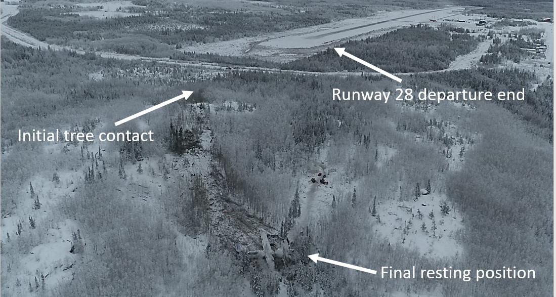
At 1812:48 the aircraft collided with the ground in a 32.0° left bank with approximately 4° of nose-up pitch. The aircraft slid along the ground for about 9 seconds and came to a rest at 1812:57 (Figure 2).

1.1.7 Post-accident events
At 1812:57, the captain and FO, still strapped into their seats with the cockpit section sitting on its right side, began to carry out emergency procedures. To ensure the engines were shut down, the FO pulled the right engine fire handle at 1813:25 and the left fire handle shortly afterward.
At 1814:39, the flight crew carried out the checklist for ON GROUND ENG FIRE OR SEVERE MECHANICAL DAMAGE and set the emergency locator transmitter to ON. After completing that checklist, the pilots determined there was no communication between the cabin and the flight deck, and chose not to carry out the ON GROUND EMERGENCY EVACUATION checklist.
At 1817, the FO called West Wind dispatch on his cellphone to let them know about the accident and to request assistance. A West Wind flight follower who received the phone call activated the company emergency response plan.
1.2 Injuries to persons
All 22 passengers and 3 crew members were injured (Table 1). Many were rendered temporarily unconscious. The captain and 9 passengers were seriously injured, and 1 of the seriously injured passengers died 12 days after the accident as a result of the injuries received.
| Degree of injury | Crew | Passengers | Persons not on board the aircraft | Total by injury |
|---|---|---|---|---|
| Fatal | 0 | 1 | – | 1 |
| Serious | 1 | 8 | – | 9 |
| Minor | 2 | 13 | – | 15 |
| Total injured | 3 | 22 | – | 25 |
For more detailed information on injuries, see section 1.15.4 Direct effect on occupants.
1.3 Damage to aircraft
The aircraft was destroyed.
Further detailed description of damage to specific structures and components is provided in section 1.12 Wreckage and impact information.
1.4 Other damage
The aircraft collided with trees and the ground in a forested area, causing localized disruption to the forest in the impact zone and debris field.
The aircraft departed CZFD with approximately 3068 L of Jet A fuel on board; however, only 1200 L were recovered following the accident. The remaining 1800 L were spilled on the forest floor during the accident sequence.
1.5 Personnel information
1.5.1 General
Records indicate that the captain, FO, FA, and dispatcher were all certified and qualified with respect to their active roles, in accordance with existing regulations.
| Captain | First officer | |
|---|---|---|
| Pilot licence | Airline transport pilot licence (ATPL) | Airline transport pilot licence (ATPL) |
| Medical expiry date | 01 June 2018 | 01 April 2018 |
| Total flying hours | 5990 | 15 769 |
| Flight hours on type | 1500 | 7930 |
| Flight hours in the 7 days before the occurrence | 18.5 | 7.0 |
| Flight hours in the 30 days before the occurrence | 94.3 | 77.6 |
| Flight hours in the 90 days before the occurrence | 212.3 | 200.5 |
| Flight hours on type in the 90 days before the occurrence | 212.3 | 200.5 |
| Hours on duty before the occurrence | 4.7 | 4.7 |
| Hours off duty before the work period | 19.5 | 19.5 |
1.5.2 Captain
The captain was hired by West Wind on 25 June 2010. In November 2015, he began operating the ATR 42 as an FO and, by July 2017, he was promoted to captain. He had approximately 400 hours as pilot-in-command (PIC)Footnote 18 on the ATR 42.
The captain was on reserve duty the day before the occurrence but did not fly. On 13 December 2017, he began duty at 1330 and reported feeling rested. The planned duty period was about 9 hours. Fatigue was not considered a contributing factor in this occurrence.
A review of training records determined that the captain had completed all required company initial and recurrent training, including:
- Emergency/Fire Evacuation Procedures – 07 May 2016
- SMS [Safety Management Systems] for Employees – 23 January 2017
- Ground and In-Flight Icing Training – 26 September 2017
- ATR 42 Recurrent Ground School – 04 June 2017
- Crew Resource Management (CRM) – 06 June 2017
1.5.3 First officer
The FO was hired by West Wind on 15 June 2000 as an FO on the British Aerospace BAE-31 Jetstream. In November 2005, he began flying the ATR 42 as an FO. In May 2011, he was promoted to a captain position on the ATR 42. On the day of the occurrence, the FO, who usually flew as a captain, was scheduled to fly as an FO due to the unavailability of FOs.
The FO was on reserve duty the day before the occurrence but did not fly. On 13 December 2017, he began duty at 1330 and reported feeling rested. The planned duty period was about 9 hours. Fatigue was not considered a contributing factor in this occurrence.
A review of training records determined that the FO had completed all required company initial and recurrent training, including:
- Emergency/Fire Evacuation Procedures – 01 June 2016
- SMS for Employees – 29 January 2017
- Ground Icing Training – 23 September 2017
- In-Flight Icing Training – 30 September 2017
- ATR 42 Recurrent Ground School – 04 June 2017
- Crew Resource Management – 17 June 2017
1.5.4 Flight attendant
The FA was hired by West Wind on 09 February 2015 and completed initial FA training on 16 March 2015. She then completed line indoctrination on the ATR 42 on 26 March 2015. In March 2017, the FA completed annual FA recurrent training, which included CRM training.
The FA had been on leave for 5 weeks before the accident. West Wind required the FA to review emergency procedures before returning to work. The FA was on reserve duty the day before the occurrence but did not fly. The occurrence flight was the second day back to work for the FA.
On 13 december 2017, the FA began duty at 1330 and reported feeling rested. The planned duty period was about 9 hours. Fatigue was not considered a contributing factor in this occurrence.
1.5.5 Flight dispatcher
The dispatcher was hired by West Wind in 2012 in another role and completed initial dispatch training in November 2017.
On 13 december 2017, the dispatcher began duty at 1200 and reported feeling rested. The planned duty period was about 8 hours. Fatigue was not considered a contributing factor in this occurrence.
1.6 Aircraft information
1.6.1 General
The ATR 42-320 is a pressurized twin-engine turboprop produced by ATR and type-certified in the transport category.
The occurrence aircraft was manufactured in 1991 and acquired by West Wind in 2012. It was configured with 44 passenger seats.
| Manufacturer | ATR-GIE Avions de Transport Régional (ATR) (formerly Aerospatiale) |
|---|---|
| Type, model, and registration | ATR 42-320, C-GWEA |
| Year of manufacture | 1991 |
| Serial number | 240 |
| Certificate of airworthiness / flight permit issue date | 04 March 1988 |
| Total airframe time | 26 481.3 hours, 32 051 cycles |
| Engine type (number of engines) | Pratt & Whitney Canada PW121 (2) |
| Propeller/rotor type (number of propellers) | Hamilton Sundstrand Model 14SF-5 (2) |
| Maximum allowable take-off weight | 37 258 pounds |
| Recommended fuel type(s) | MIL-T-5624, Grade JP5, AST-MD-1655 Grades JET A, Jet A1 |
| Fuel type used | Jet A |
The ATR 42-320 is built with the wing mounted at the top of the fuselage. The empennage is configured with the horizontal tail surface mounted on the top portion of the vertical stabilizer, also known as a T-tail. The height above ground of the wings is 3.76 m and of the horizontal tail surface is 7.75 m. These horizontal surfaces have a combined surface area of approximately 66.2 m2 (Figure 3).
![Illustration of ATR 42 profile (Source: Avions de Transport Régional, ATR 42 Airplane Flight Manual, Revision no. 24 [July 2013], Chapter 01, section 03, p. 1, with TSB annotations)](/sites/default/files/eng/rapports-reports/aviation/2017/a17c0146/images/a17c0146-figure-03.jpg)
1.6.2 Aircraft ice protection systems
The ATR 42 is equipped with an icing advisory system. This system includes an ice detector located on the left wing, an icing evidence probe located on the lower frame of the left cockpit side window and visible to both pilots, and an indicator light located on the central annunciator panel.
The ATR 42 ice protection system permits the aircraft to operate in icing conditions. Ice protection is provided to critical areas of the aircraft by 2 aircraft systems: an electrical system that provides heat to the pitot and static ports, AOA vanes, windshields, propellers, and flight control horns; and a pneumatic system that provides bleed air from the engines to the outboard leading-edge wing de-icing boots, horizontal stabilizer leading-edge boots, engine air intakes, and engine gas path (Figure 4).
![Diagrams showing ice- and rain-protected areas of the ATR 42 (Source: Avions de Transport Régional, ATR 42 Flight Crew Operating Manual, Revision no. 41 [August 2015], Part 1, Chapter 13, section 10, p. 2)](/sites/default/files/eng/rapports-reports/aviation/2017/a17c0146/images/a17c0146-figure-04.jpg)
The ice protection system is controlled by an overhead panel in the cockpit. The panel is divided into 3 segments that allow the flight crew to select the desired level of protection. Level 1, 2, and 3 are terms used by West Wind to describe the icing protection that has been selected on the aircraft. Level 1, or “permanent protection,” includes the probes, ports, and front windows. Level 2, or “anti-icing” adds propellers, horns, side windows, and engine intakes. Level 3 or “de-icing” adds all remaining protection, including wings and stabilizer.
1.6.3 Procedures for atmospheric icing conditions
When atmospheric icing conditions are present, aircraft performance can be degraded. To account for this, specific procedures must be followed. These procedures normally include engaging icing protection and adjusting speeds to ensure that margins of safety are maintained. The change to these speeds can also have an effect on take-off and landing distances.
The limitations section in the ATR 42 Airplane Flight Manual (AFM) states that
Atmospheric icing conditions exist when :
– OAT [outside air temperature] on the ground and for take-off is at or below 10° C or when TAT [total air temperature] in flight is at or below 10°C,
– and visible moisture in any form is present (such as clouds, fog with visibility of less than one mile, rain, snow, sleet and ice crystals). Footnote 19
The normal procedures section describes what must be done when these conditions are present:
Procedure for operation in atmospheric icing conditions :
- As soon as and as long as atmospheric icing conditions exist, the following procedures must be applied :
ANTI–ICING (propellers, horns, side–windows, engines)………………………………ON
PROP MODE SEL................................................................................................ According to SAT
NP set.................................................................................................................................... set ≥ 86 %
Minimum maneuver / operating icing speed...................... BUGGED AND OBSERVED
ICE ACCRETION............................................................................................................... MONITOR
NOTE : horns anti-icing selection triggers the illumination of the ”ICING AOA” green light and lowers the AOA stall warning threshold.Footnote 20
1.6.4 Take-off performance calculations
When determining take-off performance calculations, numerous factors must be considered, including take-off weight, wind, temperature, pressure altitude, equipment in use, icing conditions, runway length available, runway surface and slope, and runway surface contamination. Because most of these factors cannot be changed, take-off performance calculations normally result in adjustments to the take-off weight to accommodate for the other factors. For example, procedures require increased take-off speeds in atmospheric icing conditions, which result in longer take-off distances and greater accelerate-stop distances.
Similarly, runways that are softer, such as those made of gravel or those that are contaminated, result in performance degradation, requiring greater take-off distances than those with dry, hard surfaces. At locations where runways are relatively short, the calculated take-off distances can be greater than the distances available, necessitating a reduction in take-off weight to accommodate. The specific details of how to calculate this performance, and the resulting accommodations, are published in the AFM.
1.6.4.1 Selection of icing speeds
When aircraft are designed, they must meet airworthiness standards in order to receive type certification. Many of those standards are related to take-off performance and include ensuring that obstacle clearance is maintained throughout the take-off path, even in the event of an engine failure while operating in icing conditions.
The standards contained in Chapter 525 – Transport Category Aeroplanes of the Airworthiness Manual, define the limits of this take-off path:
The take-off path extends from a standing start to a point in the take-off at which the aeroplane is 1,500 feet above the take-off surface […]Footnote 21
Thus, when determining whether icing procedures should be used on departure, flight crews must consider that the take-off path continues from the ground up to 1500 feet AGL. This flight path duration is also part of the certification standards,Footnote 22 which ensure that aircraft are designed to meet obstacle clearance requirements when the aircraft enters icing conditions during takeoff.
Even though the standards and regulations state that the take-off path continues to 1500 feet, there is no specific guidance in the manufacturer’s official documents (AFM, Flight Crew Operating Manual [FCOM]), West Wind manuals, or in the Transport Canada Aeronautical Information Manual (TC AIM) with respect to the use of icing procedures if icing conditions are perceived to exist at any point below this altitude.
The only reference identified during the investigation that suggested the take-off path extended up to the 1500 feet limit for the purposes of icing procedures was found in the Cold Weather Operations brochure published by ATR, which states the following:
Take-off in atmospheric icing conditions
According to FCOM 2.02.08 the crew must select “anti-icing” ON to prevent ice accretion on airframe. As soon as “anti-icing” is ON, what [sic] is confirmed by the “ICING AOA” light ON, the crew must monitor speed to stay in the flight envelope.
Furthermore takeoff speeds are increased while “ICING AOA” light is ON, leading to performance reduction.
NOTE: The take-off is assumed to last until the aircraft has reached 1500ft AGL or when 10 minutes elapsed from brakes release, whichever occurs first.Footnote 23
Although there were a few clouds reported below 1500 feet at the time of departure from CZFD, there was no active precipitation observed while the aircraft was on the ground. As a result, the crew determined that icing procedures were not required, chose to leave anti-icing off (although Level 1 was active), and selected non-icing speeds for the takeoff. Additionally, because the crew determined that atmospheric icing conditions did not exist, and non-icing speeds were used, the calculated take-off distance required was not increased, and take-off weights were not decreased to accommodate.
1.6.4.2 Unpaved runways
To provide guidance to those operating on unpaved surfaces, Transport Canada (TC) published Advisory Circular (AC) 700-011 in 2012. With regard to operations in winter, the advisory states:
(1) During periods of extended and deep frost, unpaved surfaces such as gravel runways can have strength characteristics similar to those of runways with paved hard surfaces. Operational experience has indicated that two weeks of ambient temperatures of −20°C or lower may be necessary for an unpaved runway to achieve strength similar to a paved hard surfaced runway. Once frozen solid, the runway will remain in this state, until ambient temperatures increase to above freezing.
[…]
(3) All applicable AFM (Aircraft Flight Manual) performance factors should be applied for frozen unpaved runway operations. The performance factors for operations contained in CASS (Commercial Air Services Standard) 724.44(3) should be applied when operating in accordance with this standard.Footnote 24
The runway surface at CZFD is treated gravel (see specific details in section 1.10 Aerodrome information). The ATR 42 AFM contains performance supplements for operations on dry unpaved runways, but not for operations on frozen unpaved surfaces.
Without specific performance penalties published by the manufacturer, and with guidance stating that frozen unpaved surfaces had qualities similar to paved surfaces, the operator and flight crew determined that a performance penalty was not required for the departure.
1.6.4.3 Runway surface contamination
Similar to the performance degradation that results from unpaved runways, surface contamination such as water, ice, or snow, can affect aircraft take-off performance.
At 0700 on the morning of the occurrence, CZFD issued a runway surface condition report for Runway 10/28 that recorded the conditions as 60% bare and dry and 40% compacted snow patches. A similar report was issued the following morning, after the accident; however, this report recorded that the compacted snow patches were no longer present.
The ATR 42 AFM states that, if more than 25% of the runway is covered by compacted snow, it should be considered contaminated, and this condition is to be used when determining aircraft performance.Footnote 25
Given that the most recent runway surface condition report had been issued 11 hours before the time of departure from CZFD, and the restricting contamination was not present 13 hours later, it could not be determined what the actual surface conditions were at the time of departure. However, surface contamination was not considered when calculating the take-off weight of the occurrence flight.
1.7 Meteorological information
This accident involved critical surfaces of an aircraft that became contaminated with ice as a result of in-flight ice accretion on approach and further ice accretion on the ground. This ice accretion was a result of the weather conditions at the time.
This section will focus on the forecast weather conditions, the actual conditions, and how the ice formed on the aircraft.
1.7.1 Forecast conditions
1.7.1.1 Flight planning
There are no recorded weather observations for CZFD, and no METARsFootnote 26 or aerodrome forecasts (TAFs)Footnote 27 are issued for the airport. The nearest airport for which METARs and TAFs are issued is CYSF, 42 NM east of CZFD. However, personnel at CZFD are available to provide a general description of local weather conditions on request.
Because there are no formal weather products for CZFD, pilots and dispatchers use the graphic area forecasts (GFAs)Footnote 28 for the area, as well as the METAR and TAF for CYSF, in planning flights to CZFD.
At 1330, after the flight crew of WEW282 arrived for their flight and approximately 1 hour before the flight’s scheduled departure time from CYXE, a company dispatcher briefed the flight crew on the weather conditions for the route.
The briefing included information about the conditions at CZFD, as observed by local personnel, and a review of the GFA for northern Saskatchewan, including the clouds and weather chart, and the icing, turbulence, and freezing level chart.
The crew were given a printed weather package, which included copies of the GFAs, METARs, and TAFs for the intended route of the flight. At the time of the briefing, there were no recent pilot weather reportsFootnote 29 and no significant meteorological information (SIGMET)Footnote 30 or aviation weather advisories (AIRMET).Footnote 31
1.7.1.2 Aerodrome forecasts
The most recent TAFFootnote 32 for CYSF available at the time of briefing had been issued at 1143. The forecast was based on automatic observations and predicted that, at the time of WEW282’s arrival at CZFD, the conditions at CYSF would be
- variable winds at 3 knots,
- visibility greater than 6 SM,
- no precipitation, and
- overcast ceiling at 1500 feet AGL.
The forecast also predicted a temporary change in weather between 1200 and 2400, for an hour or less, that involved a decrease to 4 SM visibility in light snow and mist, and an overcast ceiling at 700 feet AGL.
This aerodrome forecast was updated throughout the day, and the most recent forecast available at the time of WEW282’s departure from CZFD had been issued at 1739. This forecast predicted the conditions would be
- winds from 280°T at 5 knots,
- visibility greater than 6 SM in light snow,
- scattered clouds at 1000 feet AGL, and
- an overcast ceiling at 2000 feet AGL.
The forecast also predicted a temporary change in weather between 1800 and 0600, for an hour or less, that involved a decrease to 2 SM visibility in light snow and mist, scattered cloud at 700 feet AGL, and an overcast ceiling at 1000 feet AGL.
The guidelines for reporting TAFs in Canada are found in the Manual of Standards and Procedures for Aviation Forecasts.Footnote 33 In the manual, the only provisions for the forecast of icing in a TAF is freezing rain (FZRA), freezing drizzle (FZDZ), or freezing fog (FZFG). Fog and FZFG is to be forecast only if visibility is expected to be below ⅝ SM. There is no provision for forecasting freezing mist (FZBR) for conditions in which icing is expected to occur on surfaces, with visibility of ⅝ SM or greater, in the absence of precipitation.
Similar guidance is found in the International Civil Aviation Organization’s (ICAO’s) Manual of Aeronautical Meteorological PracticeFootnote 34 and the U.S. Federal Aviation Administration (FAA) Advisory Circular (AC) 00-45H.Footnote 35 The FAA circular specifically states, “FZBR is not a valid significant weather combination and will not be used in TAFs.”
1.7.1.3 Graphic area forecasts
GFAs are issued 4 times daily, with a validity period of 12 hours. Each issue is a collection of 6 charts: 2 charts valid at the beginning of the forecast period, 2 charts valid 6 hours into the forecast period, and the final 2 charts valid 12 hours into the forecast period. Each specified time has a chart depicting clouds and weather conditions, and a second chart depicting icing, turbulence, and freezing level conditions.
The most recent GFAs for the Prairies region at the time of briefing had been issued at approximately 1130 and were valid for 1200 and 1800. The information in the GFAs relevant to CZFD is provided in Table 4.
| Valid time | Clouds and weather | Icing, turbulence, and freezing level |
|---|---|---|
| 1200 | Overcast clouds based at 2000 to 3000 feet above sea level (ASL), topped at 8000 feet ASL, and visibility more than 6 SM | Moderate mixed icing in clouds based at 2000 to 3000 feet ASL and topped at 8000 feet ASL |
| Patchy areas of visibility 4 SM to greater than 6 SM in light snow and mist, ceilings between 800 to 1500 feet AGL | Moderate mixed icing in clouds based at 2000 to 3000 feet ASL and topped at 8000 feet ASL | |
| 1800 | Broken layer of clouds based at 2000 to 3000 feet ASL, topped at 7000 feet ASL; visibility more than 6 SM | Patchy areas of moderate rime icing in clouds based at 2000 feet ASL and topped at 7000 feet ASL |
| Patchy areas of visibility 3 to 6 SM in light snow; ceilings between 600 and 1200 feet AGL | Local areas of moderate mixed icing from the surface to 2000 feet ASL due to local freezing drizzle |
The GFA did not predict any icing outside of clouds or precipitation, such as FZFG.
The next GFA was issued at 1731 (clouds and weather) and 1732 (icing, turbulence, and freezing level) and forecast similar conditions for the CZFD area at 1800; however, the crew did not receive this new chart before their departure at 1812.
1.7.2 Actual conditions
1.7.2.1 Stony Rapids Airport aerodrome routine meteorological reports
At the time of initial briefing, the latest METAR for CYSF had been issued at 1300 and indicated calm winds, visibility 9 SM in light snow, an overcast ceiling at 900 feet AGL, temperature −11 °C, dew point −12 °C, and an altimeter setting of 30.00 inHg.
Conditions at CYSF stayed relatively consistent throughout the day. The winds remained light; however, the ceiling tended to rise toward 2000 feet AGL, and the visibility varied between 9 SM and 2 SM in light snow and occasionally mist.
While on descent into CZFD, the flight crew received the latest CYSF weather, which recorded the conditions at 1654 as winds from 260°T at 3 knots, visibility 2½ SM in light snow, a few clouds at 1400 feet AGL with a broken ceiling at 2300 feet AGL and an overcast layer at 3700 feet AGL, temperature −10 °C, dew point −10 °C, and an altimeter setting of 30.00 inHg. The crew also used this weather report for CYSF during preparation for departure out of CZFD.
Between 1654 and WEW282’s taxi for departure from CZFD at 1807, there were 13 updates to the weather at CYSF. By 1722, the automatic system at CYSF started to record icing (ICG) on its ground-based sensor, and it reported icing in each of the 7 updates between 1722 and 1800.
The 1800 METAR for CYSF recorded the conditions as winds from 270°T at 4 knots, visibility 9 SM with no precipitation, an overcast ceiling of 1900 feet AGL, temperature −10 °C, dew point −10 °C, an altimeter setting of 30.06 inHg, with a remark of icing during the past hour.
The conditions at CZFD at the time of departure were determined to be similar to those at CYSF, although visibility was uncertain, and ceilings were slightly lower, at around 1000 to 1500 feet AGL.
Guidelines for the reporting of METAR weather observations in Canada are found in the Manual of Surface Weather Observation Standards (MANOBS). Observations at some locations, such as CYSF, are taken by an AWOS, and these METARs are annotated with “AUTO.”
There are a few differences between AUTO stations and those with human observers. AUTO stations do not report drizzle (DZ) or FZDZ, but rather will normally report these conditions as rain (RA), FZRA, or freezing – unknown precipitation (FZUP).
If icing occurs that does not involve precipitation or fog, METARs produced by human observers report this icing in the remarks section at the end of the METAR.Footnote 36 In contrast, AUTO METARs report icing (ICG) in the remarksFootnote 37 section, regardless of the source of the icing.
There is no provision in MANOBS for METARs (whether AUTO or human-observed) to report FZBR, similar to TAF reporting.
The icing recorded by the CYSF AWOS at the time of WEW282’s ground stop at CZFD coincided with the presence of light snow; however, a review of reports from earlier in the day showed that icing was occasionally recorded during mist conditions, in the absence of fog or precipitation, therefore indicating FZBR was occurring.
1.7.2.2 Fort Smith Airport aerodrome routine meteorological report
The nearest METAR to CZFD based on human observations is from the Fort Smith Airport (CYSM), Northwest Territories, located 151 NM west of CZFD. From 1500 to 1700, the CYSM METAR reported the presence of light freezing drizzle. From 1719 to 2110, CYSM was reporting light snow.
1.7.2.3 Flight crew observations
On the day of the occurrence, 2 other flights (WEW660 and TW280) were also being operated to and from CZFD.
WEW660 was operating all day in the Lake Athabasca region and mine sites; it arrived at CZFD from CYSF approximately 12 minutes before WEW282. Because of the short distance between CYSF and CZFD, WEW660 maintained an altitude of 4000 feet, which put the aircraft between 2 layers of cloud.
On descent into CZFD, WEW660 picked up a trace of icing, which the crew was able to shed before landing at CZFD. The crew reported that there was no precipitation between when they established visual contact with the runway while on approach and when they departed from CZFD. The aircraft was on the ground for approximately 15 minutes and did not de-ice while there.
TW280, was a scheduled flight from CYXE operating the same route as WEW282. TW280 was also inbound to CZFD from the south and was approximately 6 minutes ahead of WEW282.
The crew of TW280 reported a significant amount of icing, which accumulated quickly on the descent from its cruise altitude of 20 000 feet. The crew expedited the descent to minimize exposure to the icing conditions and reported that the worst of the icing was in the latter part of the descent, while below 10 000 feet. After the crew established visual contact with the runway, the aircraft did not encounter any precipitation on approach.
After landing at CZFD, the crew determined that the aircraft’s de-icing systems were effective at keeping ice off the critical surfaces, although some ice remained on unprotected surfaces. The aircraft was not de-iced while on the ground at CZFD and departed after approximately 35 minutes.
WEW282 encountered icing conditions for approximately 8 minutes between 8100 feet and 2900 feet while on descent and approach. The crew of WEW282 did not observe precipitation between when they established visual contact on approach and when the flight departed. The aircraft was on the ground for approximately 48 minutes.
1.7.3 Aircraft icing conditions
1.7.3.1 General
Atmospheric conditions can lead to the formation of ice on the leading-edge surfaces of an aircraft when in flight and on the whole aircraft when it is on the ground. These conditions are referred to as “atmospheric icing conditions” or “aircraft icing conditions.”
1.7.3.2 Hazards of icing
The hazards of aircraft icing are well known to the flying community; however, the fact that small amounts of ice on an aircraft can have a detrimental effect is often misunderstood and underestimated.
TC’s Guidelines for Aircraft Ground Icing Operations state the following:
A very small amount of roughness, in thickness as low as 0.40 mm (1/64 in.), caused by ice, snow or frost, disrupts the air flow over the lift and control surfaces of an aircraft. The consequence of this roughness is severe lift loss, increased drag and impaired manoeuvrability, particularly during the take off and initial climb phases of flight. Ice can also interfere with the movement of control surfaces or add significantly to aircraft weight. There is no such thing as an insignificant amount of ice. Footnote 38
Aircraft manufacturers take the hazard of icing into consideration when designing an aircraft and its lifting and control surfaces. ATR’s Cold Weather Operations brochure states:
In order to ensure a satisfactory behaviour, aircraft are carefully designed so that stall will occur initially at the inner portion of the wing and spread toward the tip as angle of attack increases. Roll moments and abruptness of lift drop are then minimised.
This stall behaviour can be completely jeopardized by ice accretions that have no particular reason to be symmetrical or regular along the entire span of the wing. Footnote 39
1.7.3.3 In-flight icing
Ice can form on aircraft in flight, mainly as a result of 3 processes: supercooled water droplets, freezing of liquid water, or the transition of vapour directly to ice. Depending on the process involved and the conditions, these accretions are normally classified into 4 categories: clear ice, rime ice, mixed ice, and hoarfrost. All of these types degrade performance, although to varying degrees.
All aircraft are affected negatively when accumulating ice in flight. However, many aircraft types are certified for flight in icing conditions and are equipped with systems to shed the ice or prevent it from forming on the aircraft’s critical surfaces when in flight.
Aircraft anti-icing systems are designed to prevent accumulation, and de-icing systems, to remove it. These systems are designed in general for in-flight icing, and, as a result, protect only the leading edges of the control surfaces where ice normally begins to adhere.
As a result of this incomplete coverage and normal limitations of the de-icing system, any ice that accumulates on areas outside of the protected areas, or ice that is not entirely shed by the de-icing system, will remain on the aircraft following an icing encounter unless removed by airflow, vibration, contact with warmer or drier air, or ground de-icing equipment.
The FCOM describes the hazard of this residual ice.
Even with airframe de-icers used according to procedure (i.e. as soon as and as long as ice accretion develops on airframe), the leading edges cannot be completely cleared of ice accretion because of existence of “unprotected” elements on the leading edges and continued accretion between two consecutive boots [sic] cycles.
This residual ice on leading edges changes noticeably the characteristics of flight BELOW the minimum operating speeds defined for ice accretion, as follows:
– Control effectiveness remains good, but forces to manoeuver in roll and to a lesser degree in pitch, may increase somewhat.
– Above the reduced angle of attack:
- An aerodynamic buffeting maybe [sic] felt which will increase with the amount of ice accumulated and angle of attack increase.
- Stability may be slightly affected in roll, but stick pusher should prevent angle of attack increase before wing rocking tend [sic] to develop [...]Footnote 40
1.7.3.4 Ground icing
1.7.3.4.1 Ground icing in the absence of precipitation
Most commonly, ground icing occurs as a result of freezing precipitation, such as freezing rain, freezing drizzle, or snow. However, ground icing can also occur in the absence of visible precipitation. Moisture in the air in liquid form (water droplets) or gaseous form (water vapour) can transition into ice or frost on contact with any aircraft surface that is below freezing temperature (0 °C).
Ice and frost affect aircraft performance by disrupting airflow around the critical surfaces, thereby reducing lift, increasing drag, and increasing the stall speed of the aircraft. No aircraft is certified or approved to depart with frost, ice, or snow adhering to its critical surfaces, with the sole exception of a small amount of frost on cold-soaked fuel tanks on specified aircraft.Footnote 41
1.7.3.4.2 Terminology related to ground icing
The underlying source of the ground icing phenomenon can be very complex. The following description has been simplified to aid general understanding, but is by no means a complete technical presentation of the subject.
Frost or ice formation without visible precipitation generally requires that the water vapourFootnote 42 in the air be near saturation conditions. An abbreviated description of the relevant concepts follows.
Water vapour pressure
Air is a mixture of nitrogen, oxygen, water vapour, and other trace gases. Water vapour pressure is a measure of the amount of water vapour in the air (“humidity”). It is typically less than 1% of the total air pressure.Footnote 43
Saturation
There is a theoretical limit to the amount of water vapour in the air at any given temperature. At this limit, the water vapour is saturated.Footnote 44 The saturation limits differ depending on whether one is considering transition into liquid water or into ice.
Condensation
When air is saturated with water vapour, condensation occurs.Footnote 45 Condensation is the transition of gaseous water vapour into liquid water droplets or solid ice crystals.Footnote 46 Condensation from water vapour directly to ice is called deposition or sometimes desublimation; ice conversion directly to water vapour is called sublimation.
Nucleation
Condensation commonly occurs on object surfaces or around microscopic dust particles in the air. These non-gaseous surfaces, called nucleation sites,Footnote 47 provide the necessary molecular structure for water molecules to organize into liquid droplets or ice crystals.
Dew point
The saturation limit is lower at lower temperatures.Footnote 48 If air containing under-saturated water vapour cools at a constant pressure and by a sufficient amount, the water vapour will become saturated and condensation will occur, either as mist droplets suspended in the air or as dew on surfaces. The temperature at which saturation occurs is the dew point. At high relative humidity, water vapour is close to the saturation limit; therefore, the air temperature is close to the dew point.
Supercooled liquid water
Water that remains liquid when cooled below 0 °C instead of transitioning to ice is called supercooled liquid water. It also can form when condensation occurs at dew points below 0 °C.Footnote 49 The temperature to which liquid water can be supercooled depends, in part, on the size of the droplets. Smaller droplets can persist as liquid at lower temperatures than larger ones before freezing.Footnote 50 In the atmosphere, the first cloud droplets may not begin to freeze until −10 °C to −20 °C. The smallest droplets may remain liquid until almost −40 °C.Footnote 51 Therefore, saturated atmospheric conditions below freezing can involve a combination of water vapour, supercooled liquid water droplets suspended in the air (as mist, fog, or cloud), and ice crystals suspended in the air.
Frost point
Similar to dew point, cooling air with under-saturated water vapour can reach the saturation limit with respect to ice. If conditions are suitable for ice-crystal nucleation, water vapour will condense as ice crystals (frost). This temperature is the frost point, which is always higher than the dew point temperature, by approximately 10%. For example, an air mass with a dew point of −10 °C has a frost point of −8.9 °C.
The frost deposition rate depends on a number of factors, including the temperature difference between the surface and the air, and the amount of over-saturation (the “surplus” water vapour beyond the saturation limit).Footnote 52
Latent heat
The condensation or freezing of water releases thermal energy, known as latent heat, into the surrounding air. This energy can affect the rate of freezing. Although it may slow the initial deposition of frost or ice, it will not prevent it. The thermal energy released from condensation will eventually diffuse away from the aircraft by convectionFootnote 53 and conduction within the air.
Mist or fog
The only distinction between mist and fog is the visibility level, as fog is denser. Both mist and fog are liquid water droplets suspended in the air that form as the result of condensation of saturated water vapour. If the temperature is below 0 °C, they are supercooled droplets. Mist droplets (about 0.02 mm diameter)Footnote 54 are about 100 times smaller than rain drops, and individual droplets are generally not discernible to the naked eye.Footnote 55 Mist droplets are about 25 times smaller than drizzle, which has the smallest precipitation drops that fall by gravity.
1.7.3.4.3 The cooling process
As an air mass that contains water vapour cools, whether the water vapour transitions to liquid water, supercooled liquid water, or ice depends on the vapour pressure and the temperature (Figure 5).

At temperatures above 0 °C, the saturation curve (line labelled vapour pressure over water in Figure 5) represents the transition boundary between water vapour and liquid water, with water vapour below the curve. The closer the temperature is to the curve, the higher the relative humidity. Directly on the curve, the water vapour is saturated with respect to liquid water (100% relative humidity), and, above the curve, the water vapour condenses into liquid water droplets in the air (mist or fog) or on an object’s surface (dew).
Below 0 °C, there are 2 saturation curves to consider. The first, the ice-vapour saturation curve (line labelled vapour pressure over ice in Figure 5), represents the transition boundary between water vapour and ice. Below the curve, the water is vapour. On the curve, the water vapour is saturated with respect to ice. Above the curve, the water vapour condenses directly to ice (frost deposition), provided suitable nucleation sites are available for ice crystals to form.
For example, in Figure 5, consider air with water vapour at point A that cools (at constant vapour pressure) upon contacting a cold surface. When it meets the ice-vapour saturation curve at point B, the water vapour will transition to frost crystals. The temperature at point B is the frost point.
If suitable nucleation sites are not available, ice crystals cannot form. Water can remain in the air as vapour that is over-saturated with respect to ice.
The second saturation curve below 0 °C is for supercooled liquid water (line labelled vapour pressure over supercooled water in Figure 5). At point C, the water vapour becomes saturated with respect to liquid water. This temperature is the dew point, below which the water vapour will condense into supercooled liquid water droplets (sub-zero mist).
Supercooled droplets will transition into ice as soon as suitable nucleation conditions are encountered. This can occur rapidly as clear ice forming on contact with any cool surface.Footnote 56 If such supercooled mist droplets at point D encounter an aircraft surface, they will freeze instantly as clear ice.
1.7.3.4.4 Formation of frost versus clear ice
Because supercooled mist droplets will freeze on contact with a cool surface, water vapour close to saturation (high relative humidity) presents a high risk for ground icing at sub-zero air and surface temperatures.
If the air contacts a sub-zero surface that causes the air temperature to drop, the water vapour will be saturated and transition to ice crystals as frost.
If, instead, the air cools on its own, the water vapour will be over-saturated with respect to ice until the dew point is reached. Once the dew point is reached, the vapour will condense to supercooled liquid water droplets as mist. If these supercooled mist droplets then contact a cold surface, they will instantly transition to ice crystals as clear ice.
1.7.3.4.5 Aircraft surface temperature
During WEW282’s flight from CYPA to CZFD, the aircraft climbed to FL220. During the flight, the aircraft was in air below −10 °C for about 1 hour 40 minutes, of which more than an hour was in air from −35 °C to −38 °C. The aircraft structure would have cooled during the flight in the colder air at altitude.
Aircraft surface temperature following landing depends mainly on the air temperature and time spent at altitude. Although an aircraft descends into generally warmer air at lower altitudes, surface temperature change takes time. Some surfaces can still be colder than the surrounding air after the aircraft has landed. In particular, cold-soaked fuelFootnote 57 in the tanks can keep some surfaces colder than the ambient temperature.
On the ground, there can be significant temperature differences across aircraft surfaces and between surfaces and the surrounding air, and these can change over time. Freezing conditions can be encountered on some, all, or none of the aircraft’s surfaces at any given moment.
After the aircraft shuts down, surface temperatures will continue to change in a complex way. Both cold and warm surfaces tend to approach the surrounding air temperature. Heat sources such as engines, an auxiliary power unit, or warm fuel can cause local areas of the aircraft to remain warmer than the ambient temperature. Ambient wind or propwash can carry heat to or away from the aircraft. Changes in air temperature, wind conditions, precipitation, and cloud cover can all affect the local surface temperatures over time. Surfaces ultimately tend to settle at several degrees below the ambient temperature because of radiational cooling.Footnote 58
Any spot on the aircraft with a sub-zero surface temperature is vulnerable to ice formation.
1.8 Aids to navigation
All aids to navigation were serviceable and had no effect on this occurrence. WEW282 was using RNAV navigation for the flight to and from CZFD.
1.9 Communications
CZFD is an uncontrolled airport located within uncontrolled airspace. The airport has an aerodrome traffic frequency (ATF) area with a radius of 5 NM that is centred on the airport and extends vertically up to and including 3900 feet ASL. The ATF is 123.2 MHz.
The crew of WEW282 made all the required ATF calls during their arrival at and departure from CZFD.
1.10 Aerodrome information
The Fond-du-Lac Airport (CZFD) is owned and operated by the Saskatchewan Ministry of Highways and Infrastructure. The airport is located approximately ½ km north of the Fond Du Lac Denesuline First Nation.
CZFD is available for use 24 hours a day, 7 days per week, supporting both day and night visual flight rules and instrument flight rules operations. The airport is normally unattended, and hours of operation are at the discretion of the local contractor, who carries out daily inspections and maintenance work at the airport for the Ministry. There is no de-icing/anti-icing facility or service provider at CZFD, nor is such a facility or provider required by regulations.
1.10.1 Runway 10/28
CZFD has a single runway, Runway 10/28, and at the time of the occurrence Runway 28 was in use. The take-off run, accelerate-stop distance, and landing distance available are all 3805 feet, whereas the take-off distance available is 4297 feet, accounting for a 492-foot clearway at the end. The runway is 75 feet wide and has a treated gravel surface with an uphill slope of 0.43%.
Runway 10/28 at CZFD was reconstructed and sealed in 1999. Before the reconstruction, the runway surface was straight gravel. The process involved spreading and packing gravel over the sub-base before applying the seal (consisting of liquid asphalt and aggregate) to the runway, followed by compaction using a rubber tire roller. After a setting period, the loose gravel was swept off and a second layer of seal was applied using the same process.
1.10.2 Treated gravel guidance
A treated gravel surface, sometimes called chip seal, differs from both gravel and paved surfaces. The surface consists of a firm base of gravel pavement structure, covered with a thin layer of asphalt-stabilized material that helps to keep the moisture out. A variety of asphalt emulsions and cover aggregate combinations can be used when applying a treated (seal) coat, resulting in a surface that can accommodate varying loads.
Since the treated surface is not bonded to the sub-surface, as asphalt is, TC does not consider the runway surface as paved, stating in its 2012 Advisory Circular (AC) 700-011, that
[s]eal coated runways may lack the surface bearing strength of paved hard surface runways, and in this respect are more characteristic of runways with unpaved surfaces.Footnote 59
Since the most common cause of operational problems on unpaved runways is failure of the surface layer caused by shear under high tire pressure, a measurement of the surface shear strength of the runway surface, called the California bearing ratio (CBR), is often used to determine a tire pressure limit for a given runway surface.
This ratio can be expressed as a percentage or as a whole number from 0 to 100. In the summer of 2009, Runway 10/28 at CZFD was measured and determined to have an average CBR value of 44.4. This measurement met the requirements in the ATR 42 AFM for inclusion of a penalty when calculating take-off performance; however, the 44.4 CBR summer measurement may not have been representative of the actual surface strength during the winter season at CZFD.
1.11 Flight recorders
The occurrence aircraft was equipped with a flight data recorder (FDR) and cockpit voice recorder (CVR), both installed in racks in the empennage. The FDR and CVR were recovered from the aircraft wreckage in undamaged condition and examined at the TSB Engineering Laboratory in Ottawa, Ontario. The data from both recorders were successfully recovered.
The FDR contained more than 536 hours of flight data, including the entire occurrence flight and 502 previous flights. The CVR had recorded 2 hours 4 minutes of audio from 4 separate microphones, including recordings from the captain’s and FO’s microphones, a cockpit area microphone, and an extra channel.
Further flight data were recovered from the aircraft’s EGPWS, and 2 separate FMS units. Additionally, ground-based radar data were recovered from NAV CANADA.
1.11.1 Flight data analysis
The aircraft’s detailed flight path was reconstructed using information from the aircraft’s FDR, CVR, FMS, and EGPWS, as well as the ground radar data.
The aircraft’s FMS recorded highly accurate 3-dimensional geodetic position data; however, it was recorded at a sampling rate of only 1 Hz. This sampling rate was sufficient to represent the trajectory of non-dynamic flight, such as the flight from CYPA to CZFD, but insufficient for the dynamics of the trajectory during the occurrence flight.
The FDR recorded longitudinal, lateral, and vertical accelerations relative to the aircraft body’s frame. By transforming these accelerations into the Earth’s frame of reference, and correcting for biases, an accurate flight path of the aircraft on departure was determined.
While reconstructing the flight path was relatively straightforward, accurately assessing the aircraft’s drag and lift performance, the performance of the roll control system, and the actuation of stall protection were significantly more complicated.
1.11.1.1 Drag and lift performance
1.11.1.1.1 Background
Ice contamination, even in seemingly small amounts, can lead to significant aerodynamic penalties, primarily related to drag and lift.
Drag and lift penalties are mutually dependent: a degradation in lift performance causes a degradation in drag performance. For example, in a scenario where an ice-contaminated aircraft is attempting to maintain a desired airspeed, the ice contamination will deteriorate the lift-performance of the wing, requiring a higher AOA to generate the necessary lift. The higher AOA will, in turn, generate higher induced drag. As a result of this increase in induced drag, in combination with the parasite drag from the contaminated surfaces, the required power to maintain the desired airspeed will increase.
To understand how the ice contamination affected the aircraft’s performance during the approach to and departure from CZFD, the investigation included a handling quality analysis to measure the aircraft drag and lift characteristics, using data from the aircraft’s FDR.
1.11.1.1.2 Methodology
The analysis was done collaboratively by the TSB, the Bureau d’Enquêtes et d’Analyses pour la sécurité de l’aviation civile of France (the BEA), and ATR to compare the expected and actual total forces and moments in order to identify the presence and effect of contamination on both the approach to and departure from CZFD. The analysis was carried out using an advanced desktop simulator Footnote 60 and the aerodynamic characteristics of the ATR 42-320 aircraft.
First, the engine and control inputs were analyzed to output the aircraft’s expected total forces and moments, assuming an uncontaminated aircraft. Second, the aircraft’s recorded accelerations and attitudes were analyzed to output the aircraft’s actual forces and moments. Third, the differences between the expected and actual forces and moments were analyzed to identify the effect of contamination.
1.11.1.1.3 Approach phase
The APM’s DEG PERF alert is triggered by design when the 60-second average drag increases beyond 28% higher than the reference model for a clean aircraft. During the descent to CZFD, drag progressively increased and the DEG PERF alert triggered. The point in time when the simulation indicated a 28% drag increase coincided with the point in time when the FDR on the occurrence flight recorded the DEG PERF discrete parameter.
The analysis determined that lift performance was degrading, and reached a 10% degradation at a similar time.
1.11.1.1.4 Ice detected
The FDR records an “icing detected” discrete parameter showing the status of the ice detection probe. This probe, located under the left wing, alerts the crew as soon as and as long as it senses ice accretion.
When the probe accretes more than 0.5 mm of ice, it initiates a 7-second probe heating cycle in order to shed the ice and illuminates an ICING light in the cockpit for at least 60 seconds.
The time between heating cycles is an indication of the rate at which the aircraft is accreting ice. The first heating cycle and ICING light while on descent into CZFD commenced when the aircraft was at 7600 feet ASL. The second heating cycle occurred only 46 seconds later, and the time interval between subsequent heating cycles became progressively longer. Therefore, the rate of ice accretion was greatest at 7600 feet ASL and progressively reduced until ice accretion was no longer detected at 2900 feet ASL.
The airframe de-icing system remained on for 1 minute 54 seconds after the ICING light was extinguished for the final time. This permitted the system to cycle the wing boots twice after ice accretion had stopped.
1.11.1.1.5 Occurrence departure
The drag and lift performance on departure from CZFD were analyzed using the same method as that for the approach; however, it was recognized that the results were considered accurate only once the aircraft had exited the influences of ground effect.
It was determined that the aerodynamic characteristics during the departure deviated from their references by even greater amounts than those on approach. The analysis showed that drag increased by as much 58% and lift performance degraded by as much as 25% during the occurrence departure.
1.11.1.2 Roll control system performance
1.11.1.2.1 Background
The ATR 42 roll control system uses ailerons and spoilers to control the roll attitude of the aircraft.
The dynamic roll attitude of an aircraft is influenced by many factors, including the roll moment due to deflection of the control surfaces (referred to as roll control derivative), and the opposing roll moment due to the roll rate (referred to as roll damping).
The roll control derivative is a metric for evaluating an aircraft’s roll control performance. It defines the non-dimensional contribution to the rolling moment for a given deflection angle of the control surfaces, or, to put it more generally, the effectiveness of the ailerons and spoilers. Normally, this control derivative is a constant characteristic of the airframe. However, if these control surfaces are contaminated, the aircraft’s roll control derivative may diminish.
Roll damping occurs during a roll and results from the down-going wing producing more lift than the up-going wing as a result of its increased AOA. This increased lift opposes the rolling motion and reduces or dampens the rate of roll.
When an aircraft is at or near the stall, and a roll is induced, the roll dampening that is normally present is greatly reduced. This reduced roll dampening occurs because the local span-wise AOA on the descending wing is high enough to cause local separation of the air flow over the wing and, as a result, the lift increase that normally occurs on the down-going wing (the roll dampening) is comparatively less. This changes the dynamic handling qualities of the aircraft and can lead to unexpected aircraft response to control inputs.
1.11.1.2.2 Comparison with previous flights
To assess the aircraft’s roll control performance on departure, the data from the occurrence flight was compared with that from the more than 500 flights recorded on the FDR. This comparison showed that, during the departure, the roll control derivative, or the effectiveness of the ailerons/spoilers, was reduced when compared with the average.
Because many variables can affect the calculation of the roll control derivative, this comparison could not determine the exact magnitude of the degradation.
1.11.1.2.3 Computer simulation
The computer simulation was used to analyze the roll performance. First, the simulation generated the expected rolling moment coefficient, based on aircraft control inputs; second, it generated the actual rolling moment coefficients based on the recorded angular rates. The results of the expected and actual coefficients were then compared. It was observed that a difference between the actual coefficients of lift on the left and right wings occurred without any roll control inputs, indicating that there was an asymmetry in the distribution of lift. Shortly after the introduction of this asymmetry of lift, the ailerons were deflected in an attempt to counteract the asymmetry.
While this method was unable to directly evaluate the roll control derivative, the results indicate that the effectiveness of the ailerons was not significantly degraded and had sufficient control authority to overcome the asymmetry in the lift distribution. Since the ailerons maintained sufficient effectiveness to counteract the roll, it was determined that the roll oscillations were not the result of lost aileron effectiveness.
1.11.1.3 Stall warning
The stall warning on the ATR 42 consists of an aural alert, called the stall warning cricket, a stick shaker, and a stick pusher.
The stick shaker and cricket operate using the same logic and operate simultaneously in all cases. For a flap setting of 15°, as was set for departure from CZFD, the stick shaker and the cricket should occur at an AOA vane angle of 18.1° and the stick pusher should activate at an AOA vane angle of 23.60° and deactivate at 20.10°. The stick pusher is inhibited for 10 seconds after takeoff or if the left and right AOA disagree by more than 4°.
The audible stall warning cricket was captured on the CVR during the airborne portion of the occurrence flight, after rotation and before initial impact. However, the sound from the stick shaker could not be conclusively identified, and, therefore, it could not be determined whether it activated.
During the occurrence departure, there were 2 instances of high AOA that exceeded the stick pusher threshold. At 1812:39.0, during the first instance of high AOA, although the stick pusher angle threshold was exceeded, operation of the stick pusher was inhibited because the aircraft was still within 10 seconds of weight-off-wheels.
At 1812:46.5, during the second instance of high AOA vane angle, the conditions were met for the stick pusher to activate. However, at that point, the aircraft was in a steep left bank and was beginning to collide with trees. It is possible that the unrecorded left AOA sensor differed from the right AOA sensor by more than 4°.
During the second instance of high AOA, when the stick pusher may have activated, flight data showed that the elevator was moved to a trailing-edge up position. This movement is not consistent with stick-pusher activation, but rather indicates that the elevator movement was a direct result of crew input or from the collision sequence.
1.12 Wreckage and impact information
1.12.1 Occurrence site
The aircraft took off from Runway 28, which has a runway heading of 284° magnetic or 296°T. Immediately following takeoff, the aircraft began to deviate to the left, passed over a road near the airport perimeter fence, and then proceeded toward a wooded area.
The terrain in the wooded area rises slightly, and the aircraft struck treetops in this area before contacting the ground near the top of the hill. As it made initial contact with the ground and then a secondary ridge, the aircraft left a debris trail before coming to rest. In relation to the departure end of the runway, the aircraft’s final resting position was 600 m away, on a bearing of 270°T (Figure 6).
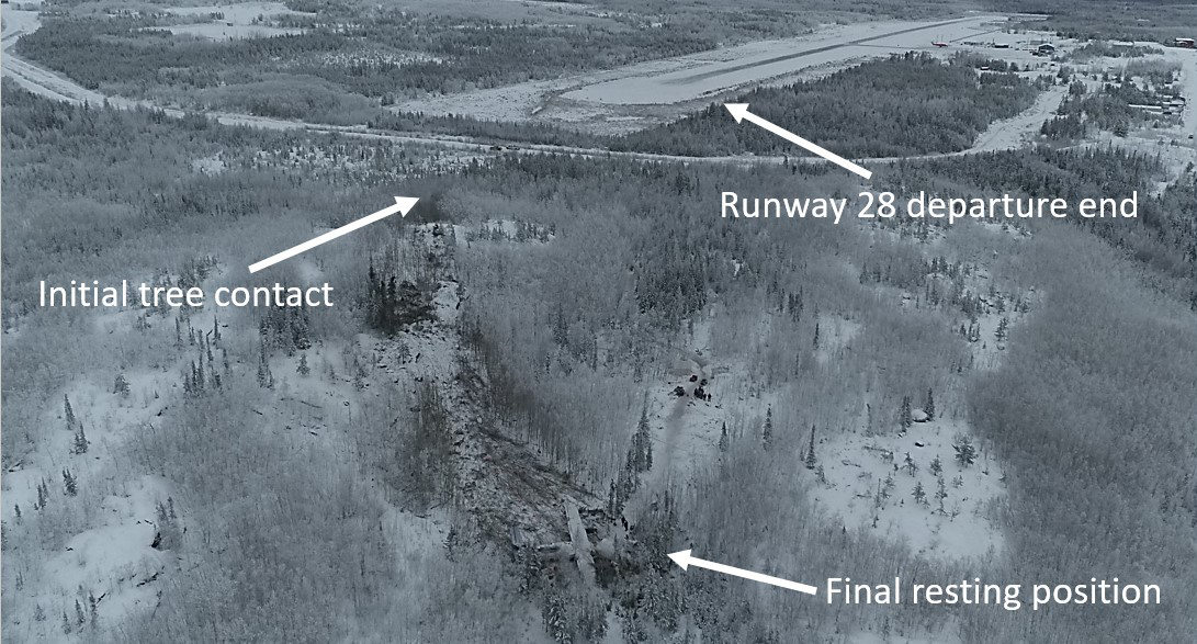
1.12.1.1 Wreckage path
The occurrence aircraft initially struck the trees approximately 430 m west-northwest of the runway. The pattern of breakage in the treetops coincided with a left bank angle of approximately 45° (Figure 7).
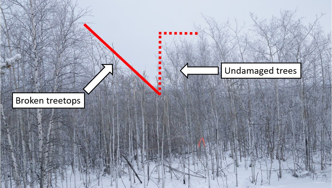
The aircraft made initial ground contact about 20 m following these tree strikes, on a track of approximately 258°T, which matched the track through the trees.
Following initial ground contact, there was secondary contact, and, approximately 70 m following the initial contact, the aircraft went over a ridge before sliding down a hill for a further 90 m.
The hill sloped down approximately 6.95° (12.11%) to the final resting position of the aircraft. While the aircraft was sliding, it rotated or yawed to its left. By the time it came to a rest, the longitudinal axis of its fuselage was almost perpendicular to the direction of travel (Figure 8).
Most of the debris was contained on the downward slope after the ridge in an area of broken trees. The path following the ridge was on a track of 247°T; 11° to the left of the aircraft’s track before the ridge.
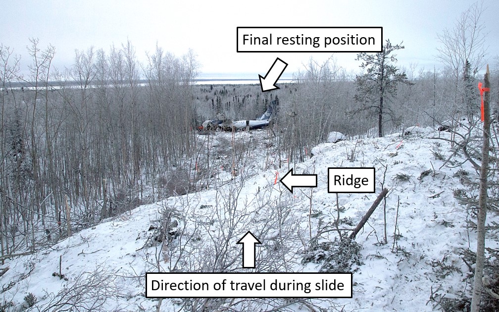
1.12.2 Aircraft wreckage
1.12.2.1 General
The aircraft came to rest rolled to its right side, with the right wing touching the ground and the left wing tipped upward (Figure 9). While the left wing tip was missing, the remainder of the wing did not fracture or bend. Both engines were still securely attached to the wings.
The bottom left of the nose section of the aircraft fuselage was crushed by the impact, although the crushing was localized just underneath the cockpit.
The fuselage had a partial, but nearly complete, transverse fracture just forward of the wing and between the 4th and 5th windows. The fracture resulted in a V-shape opening of the fuselage to the exterior environment. This transverse fracture resulted in the forward part of the fuselage partially separating from the main section of the fuselage.
Without restrictions from the wings, the forward section of the fuselage rolled approximately 90° to the right, and the remaining aft section of the fuselage rolled approximately 40° to the right, with the wing structure restricting further rotation.
The main wing structure above the centre fuselage section had collapsed downward, and some of the fuel contained in the wing had leaked into this section. The main landing gear housing structure, at the bottom of this area, was also displaced upward as a result of the impact.
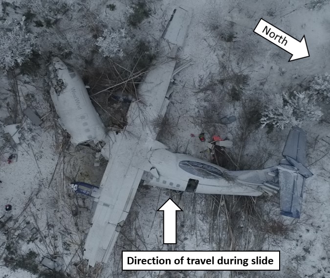
1.12.2.2 Centre fuselage
During the initial on-site examination, significant damage was observed to the centre fuselage section, underneath the wing, which had collapsed during the impact.
The main wing structure was significantly displaced downward, and the forward bulkhead of the main landing gear housing structure was pushed upward. As a result, part of the cabin floor in this area was displaced well above the cabin window (Figure 10).
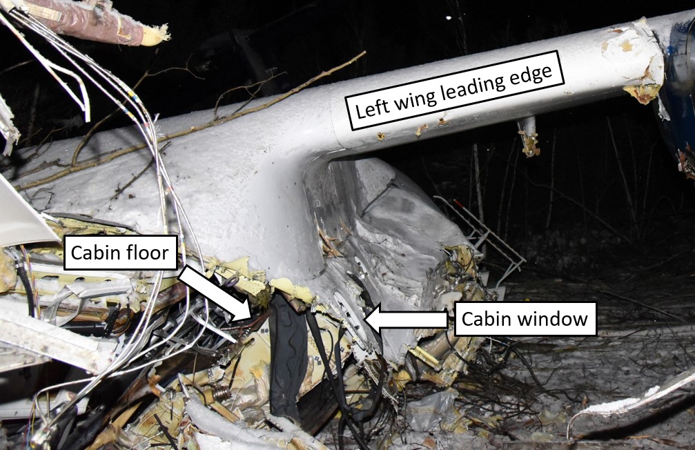
Examination of the upper portion of this centre fuselage section underneath the wing showed that the 2 strongest circular frames (frames 25 and 27), also called lift frames, had fractured. Since these lift frames support the wing and maintain the circular integrity of the cabin, these fractures had resulted in the collapse of this fuselage section.
For each frame, the fracture was approximately level with the bottom of the cabin windows, which is consistent with the vertical centre of the frames. The radius of each fractured frame was calculated to be approximately 128 cm, almost the entire original radius of the frame, which was 135 cm. This indicates that the lift frames had limited deformation before being fractured.
The lower portion of the centre fuselage section, which was built with partial bulkheads on frames 25 and 27, included a keel beam and the main landing gear box structure. There was no sign of vertical crushing on either bulkhead, although they fractured at their approximate centres. This absence of deformation indicates that this structure was too rigid to absorb the impact energy in the vertical direction.
1.12.2.3 Forward and aft fuselage
At the time of the initial on-site examination, the aft fuselage section was twisted clockwise (if viewed from rear) relative to the centre fuselage, and the twisting and rolling of this section to its right side exposed the bottom of this fuselage section. There was no evidence of significant crushing damage to the bottom of this aft fuselage section (Figure 11).
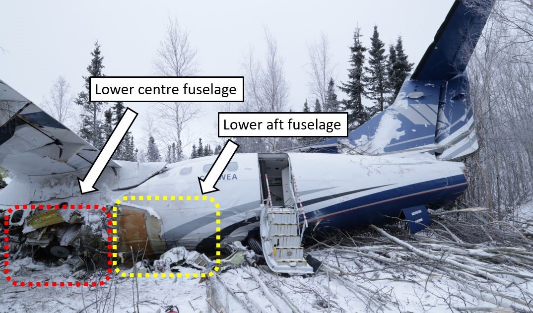
Later off-site examination of the forward fuselage section, just aft of the cockpit, showed that the left bottom area of the fuselage and the stanchions underneath the floor were crushed to some extent.
The fuselage above the floor in this area was hardly deformed by the impact, and 201 cm of the original 209 cm of interior height remained (Figure 12).

1.12.2.4 Cabin floor and seat tracks
The floor structure is an integrated part of the fuselage structure of the aircraft. The occurrence aircraft’s floor structure design uses the seat tracks as the longitudinal beams of the floor frame. Some other aircraft designs use a dedicated floor frame.
The difference between the 2 designs is that the former has the inertial load from seats (occupants) directly applied to the floor frame, whereas the latter has the inertial load from seats applied first to the seat tracks, then from the seat tracks to the floor panels, before being eventually transferred from the floor panels to the floor frames. In an accident scenario, the load distribution on the floor frames can be expected to differ between these 2 designs.
The cabin floor frame of the occurrence aircraft was constructed using transverse beams and seat tracks (Figure 13). There are 2 types of connection between a transverse beam and seat tracks, depending on whether a single piece of seat track passes over the transverse beam (type I) or if 2 seat tracks make an end-to-end connection at the transverse beam (type II).

The floor structure, including the seat tracks, failed and buckled in several locations. Examination found that, among all seat tracks examined, several type II joints had failed, whereas none of the type I joints had failed. The failure modes were either failure of the bolt or shear failure of the plate with the bolt holes on the upper cap of the transverse beam.
A longitudinal load on the seat tracks is induced when an inertial load is transmitted to the seat tracks. This can occur as a result of differential crushing deformation between different fuselage sections (due to differences in their rigidity) or as a result of deflection of the seat tracks (due to an inertial load in a vertical direction from the seat).
In keeping with this, 2 fractured seat tracks extending from the floor on top of the lower portion of the centre fuselage section were bent downward, suggesting a differential crushing between the lower portion of the forward fuselage section and that of the centre fuselage section.
The failure of the type II joints was consistent with tensile overstress due to transfer of longitudinal load from the seat track to the joint. No deformation was observed on the connecting ends of the seat tracks.
Given its smaller cross-sectional area for load transfer, the stresses experienced at the type II joint are higher than at a type I joint. This is because longitudinal tensile loads in the type II joint design must transfer through the upper cap, which is significantly thinner than the track itself. As a result, the type II joint design is considered weaker than the type I design.
1.12.2.5 Passenger seats
The first 2 rows of seats on the left and the first row of seats on the right were not occupied by passengers and were not damaged in the occurrence.
Seats from row 7 to row 11 at the rear of the passenger cabin were consistently deformed towards the right side of the aircraft; however, no sign of bending damage was observed on the horizontal tubes of the seats. The damage to these seats was consistent with the damage caused by the inertial load from the occupants in a lateral direction.
The only seats that showed a different damage pattern were the 2 left-side seats in rows 5 and 6 (Figure 14). On both of these seat pairs, the inboard legs had fractured, and the front outboard legs were deformed into a crossbow shape. This damage is consistent with an inertial load in a vertical (downward) direction from the occupants.
The front horizontal tube of the seat frames had fractured at their lateral centre, which is consistent with bending failure caused by large inertial load in a vertical (downward) direction from the occupants.
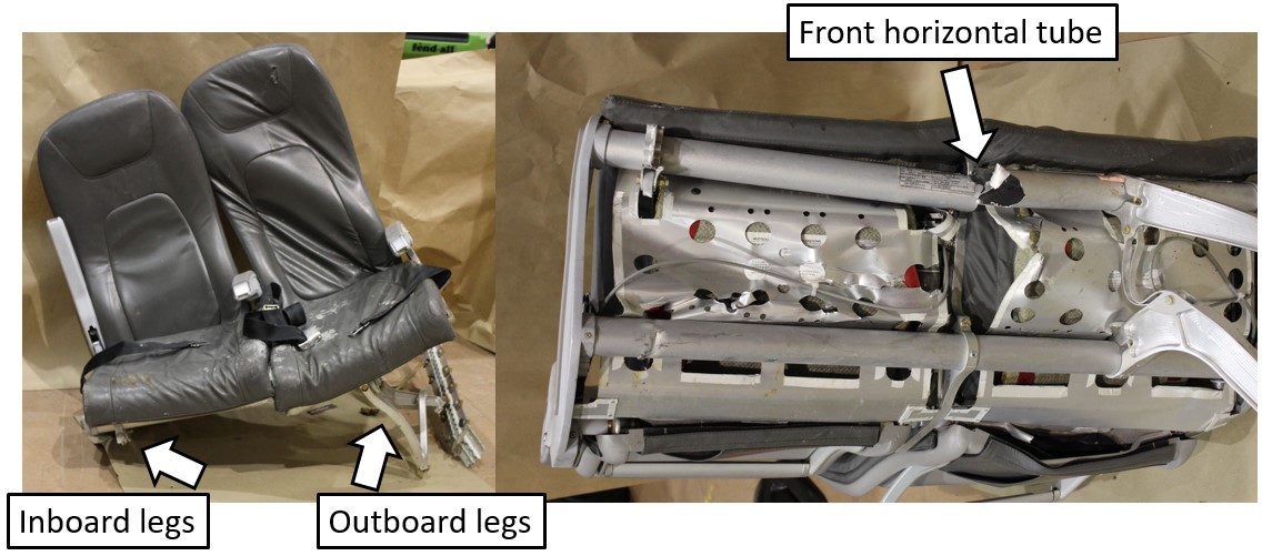
1.12.2.6 Flight attendant seat
The cabin floor between the main entrance and emergency exit showed no sign of damage or deformation; however, the FA seat was missing and was found later, broken into pieces. The seat’s bottom mounting structure was found still fastened to the floor tracks.
The FA seat was manufactured by SICMA Aero Seat of France (a part of Zodiac Aerospace of France at the time of the accident, now part of Safran). A key component of the FA seat is the structure assembly (Figure 15), a single-piece sandwich panel made of aluminum face sheets and aluminum honeycomb.
![Diagram of flight attendant seat and assembly (left image) and photos from the occurrence seat showing the honeycombing (right image) (Source of diagram: Zodiac Seats France, Component Maintenance Manual with Illustrated Parts List – Cabin Crew Member Seat, Part Number 134-Series, Revision no. 13 [10 January 2017], with TSB annotations. Source of photos: TSB)](/sites/default/files/eng/rapports-reports/aviation/2017/a17c0146/images/a17c0146-figure-15.jpg)
The structure assembly was found broken into pieces. Both the left and right legs had separated from the back panel and from their lower portions, which were still inserted into the slots of the lower fixing assembly.
Both left and right legs of the seat-structure assembly failed when their aluminum honeycomb core separated from the aluminum face sheets. The separated face sheets showed no trace of adhesive, which is consistent with adhesive failure (i.e., failure at the interface between the face sheet and adhesive).
There was evidence that extensive repairs had been made to these honeycomb panels on more than 1 occasion, as several drill holes of different diameters were identified, as were 3 different adhesives types.
Review of the service history and Component Maintenance Manual (CMM) for the FA seat indicated that the concerned FA seat had been repaired in 2014 by following a standard composite repair procedure for the ATR 42 aircraft. However, the ATR 42 structural repair manual does not cover the maintenance and repair of the seat structure.
The shop that performed the last repair on the structural assembly of the FA seat is no longer in business. Because of this, no further information could be obtained as to why it selected a standard composite repair procedure not approved for the FA seat.
The requirements for repair of the FA seat structure are detailed in the CMM from the seat manufacturer. While the general description of the seat uses the technical term “shaped honeycomb structure sandwich panel” for the seat-structure assembly, the CMM does not detail a repair procedure for such a structure assembly or for a honeycomb sandwich panel, nor does is it include the composite repair procedure found in the ATR 42 structural repair manual. In contrast, the CMM states that “Metal components which have been damaged, must be replaced; they are considered “not repairable” [emphasis added].”Footnote 61
Communication with the manufacturer of the FA seat (Zodiac Aerospace of France) confirmed that the structure assembly of the FA seat is considered not repairable and must be replaced when damage is detected.
To determine whether the unapproved repair to the FA seat of the ATR 42-320 aircraft in this occurrence was an isolated case, a reference FA seat from another West Wind aircraft (registration C-GWWC) was examined. The examination confirmed that the reference seat also had defects and unapproved repairs, effectively rendering it non-serviceable. The investigation did not determine when or by whom these unapproved repairs had been completed.
1.12.2.7 Engines and propellers
Examination of the engines and propellers on the aircraft following the accident determined that there were no abnormalities.
The on-site inspection revealed that both engines had ingested wood, wood chips, and wood dust along the gas paths. This indicated that both engines were delivering power to the aircraft during its descent into the trees. Both propellers also showed clear indications of high-speed rotation.
Subsequent analysis of recorded data confirmed that the engines were producing power as expected, and the propellers were performing as designed.
1.12.2.8 Flight controls
Flight controls were checked for proper attachment and continuity, and no defects were found in the aircraft. Trim tab positions were measured and recorded at the actuator and found to be in the proper position for takeoff.
The horizontal stabilizers had leading-edge impact damage consistent with the aircraft descending through the trees; as a result of this impact, the elevator disconnect was found disconnected.
There were no recorded data that indicated any abnormalities with the flight controls or their operation.
1.12.3 Remnants of ice contamination
1.12.3.1 TSB examination
TSB investigators arrived at the crash site 22 hours after the accident.
The right wing and control surfaces were the only parts of the aircraft where a tactile and close visual examination could be conducted. These surfaces were generally clear of contamination, except for about 1 cm of snow that had accumulated since the accident. This area of the wreckage experienced fuel leakage and substantial movement of people and equipment during the rescue operation, and it is almost certain this activity removed existing contaminants.
The left wing and empennage were photographed but were not accessible for tactile and close visual examination until 5 days after the accident. Precipitation during this period altered the condition of the surfaces, and it is impossible to precisely state the extent and severity of any contamination present during the occurrence flight based on this examination.
1.12.3.2 Earlier photographs of contamination
Examination of photographs taken by the Royal Canadian Mounted Police (RCMP) about 8 hours after the accident revealed the presence of ice contamination on the aircraft (figures 16, 17, and 18). Although ground icing conditions persisted following the crash, these figures provide some indication of the contamination present on the aircraft during the occurrence flight.
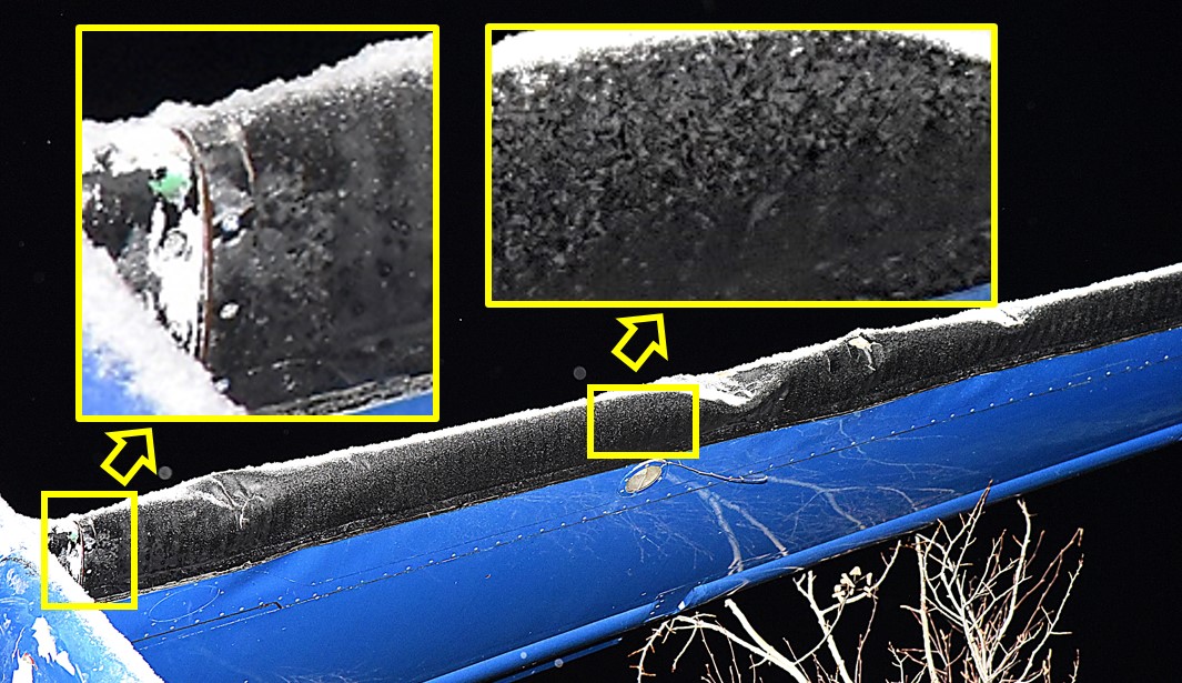
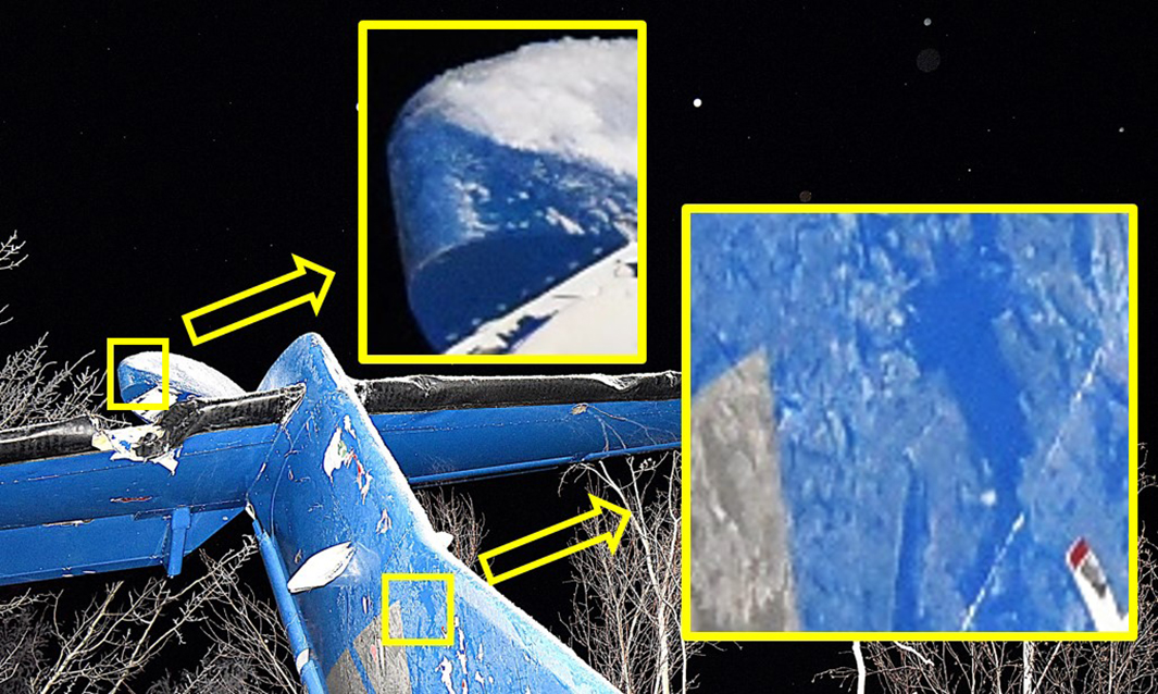
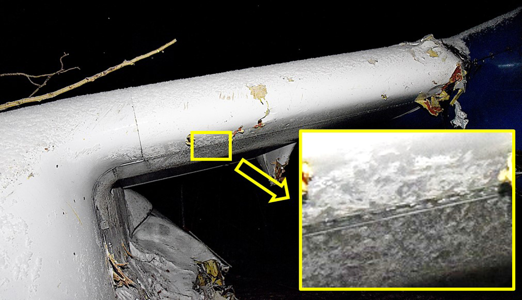
1.13 Medical and pathological information
The investigation determined that there was nothing to indicate that the performance of the flight crew or the cabin crew was degraded by medical, pathological, or physiological factors.
1.14 Fire
There was no pre- or post-impact fire.
1.15 Survival aspects
1.15.1 Crashworthiness
Crashworthiness is generally defined as the ability of an aircraft and its internal systems and components to protect the occupants from injury in the event of a crash. The key certification requirements and standards for crashworthiness applicable to transport category aircraft are contained in Chapter 525– Transport Category Aeroplanes of the Airworthiness Manual , which is based on the FAA’s Code of Federal Regulations, Title 14: Aeronautics and Space, Part 25: Airworthiness Standards: Transport Category Airplanes (FAR 25).
1.15.1.1 Aircraft design and certification
When the ATR 42 was introduced in Canada in 1993, TC issued a Type Certificate based on the aircraft’s previous U.S. FAR 25 certification in 1985.
Because the certification date was 1985, the ATR 42-320 aircraft was certified as meeting the standards of FAR 25 in place at that time, up to and including amendment 54 (1980). Hence, the ongoing production of the type had to comply only with regulations in effect in 1980, and not with the amendments to the design standards made following that date.
The FAR 25 section that primarily covered crashworthiness in amendment 54 (1980) was FAR 25.561, which stated:
- a) The airplane, although it may be damaged in emergency landing conditions on land or water, must be designed as prescribed in this section to protect each occupant under those conditions.
- b) The structure must be designed to give each occupant every reasonable chance of escaping serious injury in a minor crash landing [emphasis added] when—
- (1) Proper use is made of seats, belts, and all other safety design provisions;
- (2) The wheels are retracted (where applicable); and
- (3) The occupant experiences the following ultimate inertia forces [acting separately] relative to the surrounding structure:
- i) Upward—2.0g.
- ii) Forward—9.0g.
- iii) Sideward—1.5g.
- iv) Downward—4.5g, or any lesser force that will not be exceeded when the airplane absorbs the landing loads resulting from impact with an ultimate descent velocity of five f.p.s. [feet per second] at design landing weight.
- c) The supporting structure must be designed to restrain, under all loads up to those specified in paragraph (b)(3) of this section, each item of mass that could injure an occupant if it came loose in a minor crash landing. Footnote 62,Footnote 63
The design standards did not (and still do not) require an evaluation of the ATR 42-320 structural crashworthiness capability at the aircraft level.
This FAR 25.561 standard, from paragraph (b)(3) onward, was updated in 1988 to make an adjustment to the ultimate forces and to add a condition that would ensure passenger evacuation was not impeded:
- (3) The occupant experiences the following ultimate inertia forces acting separately relative to the surrounding structure:
- i) [Upward, 3.0g.
- ii) Forward, 9.0g.
- iii) Sideward, 3.0g on the airframe; and 4.0g on the seats and their attachments.
- iv) Downward, 6.0g.
- v) Rearward, 1.5g]
(c) The supporting structure must be designed to restrain, under all loads up to those specified in paragraph (b)(3) of this section, each item of mass that could injure an occupant if it came loose in a minor crash landing.
[(d) Seats and items of mass (and their supporting structure) must not deform under any loads up to those specified in paragraph (b)(3) of this section in any manner that would impede subsequent rapid evacuation of occupants.] Footnote 64
Crashworthiness was also enhanced in 1988 by the addition of FAR 25.562, which introduced dynamic condition requirements during an emergency landing, in addition to the static conditions required by FAR 25.561. FAR 25.562 required that seats remain attached to the floor when the floor accelerations reach 14g in a vertical (downward) direction and 16g in a longitudinal (forward) direction.
The aviation industry has widely seen the enhancements to FAR 25.561 and the introduction of the new FAR 25.562 as a step forward to enhance the crashworthiness requirements for transport category aircraft, although these were not applicable to the ATR 42. However, these amendments, and even those in effect at the time of this report’s publication, do not dictate how the structure of an aircraft is to be designed to give each occupant “every reasonable chance of escaping serious injury in a minor crash landing,”Footnote 65 and they still do not require an evaluation of the structural crashworthiness capability at the aircraft level.
1.15.1.2 Aircraft energy absorption
Scientific evidence dictates that the only way to achieve the survivability crashworthiness requirements is to have a structural design that can effectively absorb the impact energy through structural deformation or crumpling, so as to attenuate the impact force.
On vertical impact, the lower portion of the aircraft fuselage should progressively collapse and crush, thus absorbing part of the kinetic energy and attenuating the severity of the force before it can reach the occupantsFootnote 66and the upper portion of the fuselage. If the structure does not collapse and crush to absorb the kinetic energy, then the deceleration profile can transfer directly to the cabin and the seated occupants. Such a transfer of forces could cause significant structural damage to the fuselage and floor, which would breach the cabin and reduce the effectiveness of the aircraft’s restraint system while the occupants are experiencing the peak deceleration forces.
1.15.1.2.1 Previous test involving ATR 42 impact response
In 2006,the FAA performed a vertical drop test on the ATR 42 to determine the impact response of the fuselage, fuel system, floor tracks, seats, and anthropomorphic test dummies when subjected to a severe, but survivable, simulated crash impact (figures 19 and 20).
The aircraft was dropped from a height of 14 feet, which resulted in a vertical impact velocity of 30 fps (9.1 m/s). Although crushing of the lower portion of the forward and aft fuselage sections absorbed much of the impact energy, the following also occurred:
- The lower portion of the centre fuselage section underneath the wing, which was essentially the main landing gear housing structure, did not effectively absorb the vertical impact energy. As a result, the acceleration force (in g) transferred to the cabin floor of the centre fuselage section was more than 2 times higher than the acceleration force to the forward and aft fuselage sections.
- The centre fuselage sustained major structural damage and the upper portion collapsed, which was attributed to (1) the inertial load of the wing as a result of the high acceleration forces that were transferred and the subsequent failure of 2 main supporting frames (lift frames) and (2), the fracturing and failure of the main landing gear housing structure along the vertical line in the centre of the fuselage.
- A habitable environment for the passengers in the centre fuselage section was not maintained due to the crushing of the upper fuselage section by the wing and the intrusion of the main landing housing structure into the cabin.
- The passenger doors and the 2 emergency window exits were unusable.Footnote 67


1.15.2 Impact sequence of events
During the occurrence takeoff, as aircraft bank oscillations increased in severity, the aircraft began to descend and contact trees. The aircraft then collided with the ground in a 32.0° left bank with approximately 4° of nose-up pitch. The aircraft then hit more trees and rocky ground and slid across the snowy terrain for approximately 9 seconds, travelling about 90 m.
On initial impact with terrain, the bottom of the main landing gear housing structure struck the ground and high vertical acceleration forces were transmitted to the upper fuselage. As a result of the high upper-fuselage forces, the inertial load from the wing and fuel (in the wing) crushed down onto the fuselage, resulting in collapse of the centre section of the aircraft and in fuel entering the cabin. The surrounding floor structure then also collapsed.
Flight data analysis after the occurrence determined that at impact, the aircraft had a ground speed of approximately 107 knots. As a result, the longitudinal (forward) deceleration forces in the direction of travel were approximately 4g when the fuselage initially collided with the terrain. As the aircraft continued its trajectory, it rotated (or yawed) to the left. As a result of this rotation, although the peak longitudinal (forward) acceleration force was estimated to be 4g in the direction of travel, the aircraft and its occupants also received significant lateral loads nearing 4g. Ground reaction forces in the longitudinal (forward) direction then caused a transverse fracture of the fuselage just forward of the wing. This transverse fracture resulted in the forward part of the fuselage separating from the main section of the fuselage and, without restrictions from the wings, this forward section rolled 90° to the right. The remaining section of the fuselage rolled approximately 40° to the right because the wing structure restricted further rotation.
1.15.2.1 Reduction in survivable space
The structural examination found that the extent of crushing damage to the bottom of the forward and aft fuselage sections by vertical impact forces was rather limited or localized, consistent with modest vertical impact energy.
The damage to the centre fuselage section of the aircraft was similar to that found in the FAA’s drop test, although the occurrence aircraft had much lower vertical impact energy than the one in the drop test. Specifically, there were the following similarities:
- A much higher acceleration force was transmitted to the cabin floor of the centre fuselage section than that to the forward and aft fuselage sections.
- The upper portion of the centre fuselage section was crushed under the inertial load from the wing.
- The forward and aft bulkheads of the main landing gear housing structure fractured along a vertical line close to the lateral centre of the fuselage.
- The forward and aft spar bulkheads of the main landing gear housing structure did not exhibit signs of appreciable crushing in a vertical direction.
All of these observations indicate that the lower portion of the centre fuselage section did not effectively absorb the vertical impact energy of the aircraft.
The main landing gear housing structure, located beneath the fuselage, directly under the centre-forward section of the cabin, did not progressively crush in the same way as the remaining fuselage. As a result, similar to what occurred during the FAA drop test, during an otherwise survivable impact, the remaining fuselage sustained major structural damage when the wing structure directly above the main landing gear collapsed into the cabin and the floor surrounding it collapsed, resulting in a loss of survivable space.
Inside the cabin, the last row of passenger seats was upright; however, the seats in the remaining rows were progressively displaced vertically toward the ceiling of the passenger cabin due to the upward movement of the cabin floor. Objects penetrated the cabin, and the aisle became unusable as a result of the displacement of the seats and floor (Figure 21).

The tops of the seatbacks of the seats in rows 4 and 5 on the right side of the aisle had contacted or penetrated the overhead luggage compartment. The survivable space for each seat in rows 4 to 6 had been reduced to 1 to 2 feet, and the head space had been reduced in many other nearby rows (Figure 22).
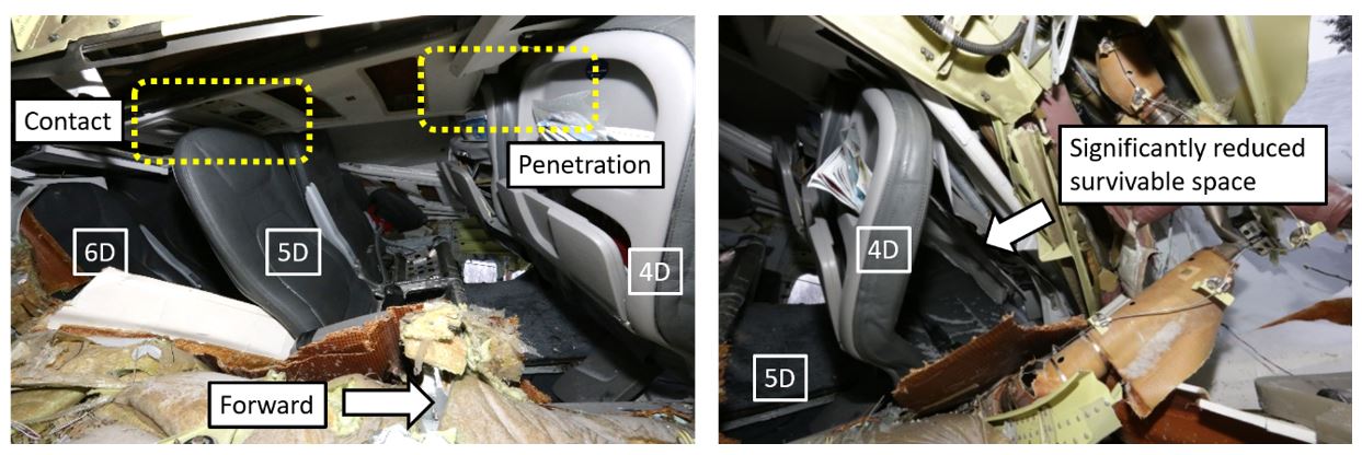
The transverse fracture and rotation of the fuselage resulted in further breach of the cabin. As the aircraft continued to slide, trees, beams, and aircraft structure pieces intruded into the survivable space. Outside of the main collapsed area, differential crushing of the lower portions of the forward and aft fuselage sections also resulted in the collapse of parts of the cabin floor in these areas.
1.15.3 Systems to reduce impact injury
1.15.3.1 Tolerance
Human tolerances to dynamic loads vary depending on factors such as the magnitude, direction, duration, and onset rate of the impact forces. Footnote 68 Aircraft impact forces typically involve vertical and longitudinal forces and, occasionally, lateral forces (from the side).
People withstand longitudinal forces better than they withstand vertical or lateral forces. Typical tolerance levels are 45g in the longitudinal (forward) direction, 20g to 25g in the vertical (downward) direction, and 20g in the lateral direction, assuming a 0.10 second crash pulse and the occupant is suitably restrained.Footnote 69
In addition to potential velocity-related injuries, an occupant has the potential to flail (uncontrolled arm, leg, and head movements), jackknife (upper torso folds forward or to the side), and/or submarine (slide out from under the belt).
In general, tolerance and response to g forces vary considerably between individuals due to factors such as age, physiology, physical health, and fitness.
Two of the most significant variables that determine how an occupant will cope with impact forces that are transferred through the cabin are the position and direction in which the occupant is seated (see section 1.15.3.2 Seats), and how well the occupant is restrained (see section 1.15.3.3 Restraints).
1.15.3.2 Seats
The regulations for transport category aircraft require that aircraft seats meet specific standards for dynamic load protection to ensure that occupants withstand as much of the loads that are transferred into the cabin during an impact as possible.
The ATR 42-320 cockpit has 2 forward-facing flight crew seats and 1 jump seat. In the aft cabin, there is a forward-facing FA seat between the rear entry door and the service door. The occurrence aircraft had 22 pairs of passenger seats distributed across 11 rows, with 2 seats on the left side (seats A and B) and 2 seats on the right side (seats C and D), for a total of 44 passenger seats. Each passenger seat was a forward-facing Geven lightweight passenger seat, and all had been replaced in 2012. The passenger seats were the type with locked-out seatbacks, designed to remain upright after flexing following an impact from the rear.
Before 1988, seats were designed and tested to withstand inertial loads from the occupants of 9g in the longitudinal (forward) direction, 4.5g in the vertical (downward) direction, and 1.5g in the lateral directions.Footnote 70 In 1988, the standard was changed and since then, it has required designs to meet an increased inertial load from the occupants acting on the seats in vertical (downward) direction (6g) and lateral direction (4g).Footnote 71
At the same time, an emergency landing dynamic conditions standardFootnote 72 was added that required all seats to be tested to withstand floor acceleration of 16g in the longitudinal (forward) direction and 14g in the vertical (downward) direction. As well as protecting against acceleration forces, the new standard required that occupants be protected from head injury as a result of contacting the seat in front of them, or other aircraft structure.
Because the ATR 42 had been designed before 1988, when it was introduced into Canada in 1993, TC issued a Type Certificate that permitted the continued use of seats designed for 9g, 4.5g, and 1.5g inertial loads in the respective directions, and did not require head impact protection. The Geven lightweight passenger seats met this original requirement, having been tested to withstand ultimate inertial loads of 9g, 7.2g, and 4g, respectively, and the FA seat in the rear of the cabin was tested to withstand loads of 9g, 7.6g, and 3g, respectively.
1.15.3.3 Restraints
As is typical on most transport category aircraft, all passenger seats were equipped with 2-point lap belts, without associated shoulder harnesses. The passenger 2-point lap belt does not restrain the upper torso and, as a result, passengers have a large flail envelope, allowing unrestrained torso, arm, and head movements on impact. In the event of an accident, occupants with 2-point lap belts are at a greater risk of concentrated acceleration forces around the hips and abdomen and can be at risk of injury as a result of potential flailing and jackknifing.
The flight crew and FA seats were each equipped with 4-point safety harnesses, and these were being worn at the time of impact. Four-point harnesses are known to be more effective at protecting the occupant, as they spread the load across the body.
The effectiveness of the overall restraint system relies on the seat remaining attached to the aircraft. On the occurrence aircraft, all of the seat structures were attached directly to the floor, and the floor deformation on impact significantly reduced the overall restraint effectiveness, regardless of seat or belt type.
As parts of the aircraft floor collapsed, passengers and crew experienced vertical, longitudinal, and lateral forces, but with reduced restraint protection. Most passenger seats remained in place, although they were displaced from the collapse and distortion. However, seats A and B in row 3 were ejected out of the aircraft through the transverse fracture. The passenger in seat 3B was ejected with the seat, but the passenger in 3A was projected into the back of seat 2B, slipping from his belt as the seat departed the aircraft.
The captain’s seat remained intact, but the floor beneath the seat collapsed as part of the initial impact forces. The integrity of the overall captain’s restraint system was compromised as a result.
The FA seat failed during the impact and, as a result, the attached restraint system was ineffective.
1.15.3.3.1 Child restraint system
The ATR 42-320 has no child restraint systems, nor is the aircraft required to have such equipment.
In 2015, following its investigation into the December 2012 low-energy rejected landing and collision with terrain in Sanikiluaq, Nunavut,Footnote 73 the TSB found that infants and children who are not properly restrained are at risk of injury and death, and may cause injury or death to other passengers in the event of an accident or turbulence.
It further concluded that, if new regulations on the use of child-restraint systems are not implemented, then lap-held infants and young children are exposed to undue risk and are not provided with a level of safety equivalent to that for adult passengers.
Therefore, the Board recommended that
[t]he Department of Transport work with industry to develop age- and size-appropriate child restraint systems for infants and young children travelling on commercial aircraft, and mandate their use to provide an equivalent level of safety compared to adults.
TSB Recommendation A15-02
In 2017, following its investigation into a March 2015 collision with terrain in Halifax, Nova Scotia,Footnote 74 the TSB restated the recommendation, after finding that an infant was injured because of a lack of appropriate child restraint. That investigation found that
[i]f new regulations on the use of child-restraint systems are not implemented, lap-held infants and young children are exposed to undue risk and are not provided with a level of safety equivalent to that for adult passengers.
When the present report was published, TC’s last response to Recommendation A15-02 had been received in February 2021 and was rated by the Board in March 2021 as showing Satisfactory Intent. Footnote 75
1.15.3.4 Bracing for impact
To mitigate the risk of injury to occupants seated in aircraft seats without torso restraints or head impact protection, such as those in the occurrence aircraft, it is important that those occupants assume a proper brace position.
In this occurrence, the flight crew, although aware of imminent collision, did not have time to communicate a “BRACE BRACE BRACE” command to the cabin.
Because the FA was not aware of the imminent collision and did not receive any commands from the flight crew, she did not provide passengers with any emergency commands, such as “Bend over, keep your head down.”
Following the initial impact, although the impact sequence continued for a further 9 seconds, the FA was unable to issue any commands because her seat had ejected from its position, projecting the FA into the aisle.
In an anticipated emergency and if time and circumstances permit, in accordance with regulations,Footnote 76 West Wind FAs are required to provide passengers with an additional emergency briefing that includes a demonstration, practice, and observation of the brace position(s).
However, in an emergency that is not anticipated by the cabin crew, or if the cabin crew become incapacitated, passengers who have not read the safety features card would have no information on how to assume the required brace position.
West Wind’s pre-departure safety briefing did not include any explanation or demonstration of the brace position(s), nor was it required to. Passengers were instead instructed to review the safety-features cards, which contained illustrations on how to brace. Only those passengers with special requirements were provided with additional safety information briefings and/or demonstrations.
Passengers typically pay little attention to safety-features cards.Footnote 77 A study by the U.S. National Transportation Safety Board found that 68% of commercial flying passengers do not read the safety-features cards.Footnote 78 A 2006 study by the Australian Transport Safety Bureau found that 65% of commercial flying passengers do not read the card.Footnote 79 Instead, passengers typically rely more on information provided by the crew at the time of the emergency.
In this occurrence, even if passengers had referred to the safety-features card, the brace position information did not reflect current advised brace positions. In 2016, TC issued an Advisory CircularFootnote 80 to provide operators with updated guidance to modify the existing Canadian recommended brace position.
It recommended that passengers place their hands down by their lower legs instead of on the back of the seat in front of them. This recommendation is intended to reduce the chance of limb-flailing injuries and/or of the passenger pushing the seat in front of them forward. It also recommended that passengers place their legs either vertically (down) or aft, rather than extending them forward, which should reduce the chance of leg-flailing injuries.
Although TC modified the recommended brace position, the Advisory Circular was not mandatory and therefore the continued use of the original brace position was permitted. As a result, at the time of the occurrence, the original brace position remained on the ATR 42 safety-features card, which still advised passengers to place their hands on the seat in front of them and did not emphasize the importance of the leg position (Figure 23).

In a 2015 accident in Halifax, Nova Scotia, involving a transport category aircraft that collided with terrain,Footnote 81 similar to this accident, the passengers and cabin crew were not in a brace position at the time of the initial impact because no emergency was expected. In that occurrence, during subsequent impacts, the cabin crew was able to shout, “Bend over, keep your head down.” Some passengers attempted to adopt a brace position, either on their own or in response to the shouted command, but they did not know how to properly brace themselves because they had not read the safety-features card.
Passengers involved in that accident had injuries to hands and wrists that were consistent with attempting to hold onto the backs of the seats in front of them or placing their hands forward to brace themselves. Most of the injuries sustained by passengers in that occurrence were consistent with not adopting an appropriate brace position.
1.15.4 Direct effect on occupants
1.15.4.1 Injuries by location
All passengers and crew were injured during the accident sequence. Many were rendered temporarily unconscious. The captain and 9 passengers were seriously injured, and 1 of the seriously injured passengers died 12 days after the accident. The severity of the injuries was somewhat distributed throughout the aircraft (Figure 24); however, the passenger who was fatally injured was seated mid-cabin, directly beneath the wing.
![Injury distribution (Source: Avions de Transport Régional, Cabin Crew Operating Manual, Revision no. 4 [April 2018], with TSB annotations)](/sites/default/files/eng/rapports-reports/aviation/2017/a17c0146/images/a17c0146-figure-24.jpg)
1.15.4.2 Injuries to passengers
During the impact and resulting slide, most passengers were thrown about in their seats, striking the seats in front of them and then the aircraft structure as a result of the acceleration forces and the changing direction of those forces.
As the impact sequence progressed, passengers experienced more severe flailing injuries when the aircraft structure and external objects, such as trees, intruded into their survivable space. Passengers experienced injuries consistent with acceleration forces, jackknifing, and flailing, such as back, head, arm, and leg injuries.
Passengers in the middle-forward left section of the aircraft also suffered crushing injuries, such as major head, body, and leg trauma. These injuries resulted from the reduction in survivable space between the floor above the main landing gear and the collapsed upper fuselage. Of the 3 passengers in this area, 2 received serious, life-changing injuries, and the third died as a result of these injuries 12 days after the accident.
Back-related trauma was more common in the right middle to rear section of the aircraft. This type of trauma is consistent with the lateral forces and rotation applied to this side of the aircraft, which resulted in lateral deceleration forces affecting the passengers in seats that had a compromised restraint system.
One passenger suffered projection injuries when their seat ejected from the aircraft. Many passengers throughout the aircraft had their legs trapped when the floor collapsed, resulting in knee and leg bruising. The floor collapse reduced the integrity of the restraint system and deformed the seats’ structure, which resulted in many seats being squashed together and trapping the legs of the passengers.
Those who braced by placing their arms on the back of the seat in front of them still experienced flailing-arm injuries. One passenger braced with their head down between their legs. This passenger did not have flailing injuries, but they did have head and neck injuries from the seat in front of them pushing back into their survivable space.
1.15.4.3 Injuries to crew
When the FA’s seat detached during the impact sequence, she became unrestrained and was propelled forward into the aisle, suffering multiple projection injuries to the legs, hands, and head.
As the floor collapsed underneath the captain’s seat, compromising the restraint system, the captain suffered acceleration forces injuries, namely, serious back fractures, which limited his ability to evacuate on his own.
The FO suffered minor flailing and leg-compression injuries as a result of the damaged aircraft structure imposing into his survivable space.
1.15.4.4 Injury to infant
An infant, who was held unrestrained on the lap of their parent who was seated in 11C, experienced projection injuries as a result of hitting the seat in front. This infant then experienced crushing injuries when that seat was pushed back into the survivable space.
1.15.5 Effect on evacuation routes
1.15.5.1 Cabin configuration
![Occurrence aircraft’s cabin configuration (Source: Avions de Transport Régional, Cabin Crew Operating Manual, Revision no. 4 [April 2018], with TSB annotations)](/sites/default/files/eng/rapports-reports/aviation/2017/a17c0146/images/a17c0146-figure-25.jpg)
1.15.5.2 Main and evacuation aisle
Differential crushing of the fuselage area caused the floor and seat tracks to deform, which, in turn, resulted in a significant reduction or elimination of the main aisle. Without the main aisle, passengers did not have access to the primary route to the emergency exits, and many passengers had to climb over seatbacks to gain access to an evacuation route.
1.15.5.3 Emergency exits
The ATR 42 has 4 doors in the cabin that can be used as emergency exits by the passengers, and a pilot emergency hatch for emergency egress from the cockpit (Figure 26).
![Normal and emergency exits on the ATR 42 (Source: Avions de Transport Régional, ATR 42 Flight Crew Operating Manual, Revision no. 41 [August 2015], Part 1, Chapter 00, section 30, p. 1, with TSB modifications and annotations)](/sites/default/files/eng/rapports-reports/aviation/2017/a17c0146/images/a17c0146-figure-26.jpg)
The main entry/exit point for passengers and crew is the rear entry door (L2), which is located on the rear left side of the aircraft and is equipped with stairs on the reverse side. To open from the inside, this door is manually unlocked by moving the door control handle up to the OPEN position and then pushing the door forward until the door and stairs swing down to the ground (Figure 27).
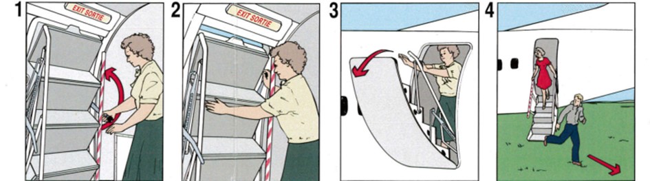
Opposite the rear entry door, on the rear right side of the aircraft, is the service door (R2). This door is manually opened outwards and can be used as an emergency exit if required.
At the front of the passenger cabin, in row 1, there are 2 emergency exits—one located on each side of the aircraft (L1 and R1). Both of these emergency exits are removed manually and must be opened, pulled in, then rotated and thrown out of the aircraft.
All 4 doors can be opened from either inside or outside the aircraft.
The aircraft is also equipped with a main cargo door on the forward left side of the aircraft, which provides the main loading point for cargo. This door opens outward either electrically or manually (with a hand crank), but can be operated only once unlatched from the outside. For this reason, the cargo door is not useful as an emergency exit.
The main access point to the flight deck from the cabin is the cockpit door, which is forward of the cargo bay. To exit the aircraft, the flight crew must first go through the cockpit door into the cabin, and then out of one of the cabin exits.
If the cockpit door is blocked, there is an emergency overhead escape hatch in the cockpit that is equipped with a stowed emergency rope ladder and built-in steps for egress. This hatch opens inward and can be opened from either inside or outside the aircraft.
1.15.5.4 Effect of damage on exits
The crushing, fracture, and differential rotation of the fuselage resulted in significant obstructions to the aircraft’s exits.
The forward part of the aircraft, including the cockpit, rolled 90° to the right and came to rest lying on its right side. Emergency exit R1 was squashed at the bottom of the fuselage, and emergency exit L1 was vertically at the top. The 90° orientation also placed the cockpit emergency hatch on the side of the aircraft, where it was partially blocked by trees (Figure 28).
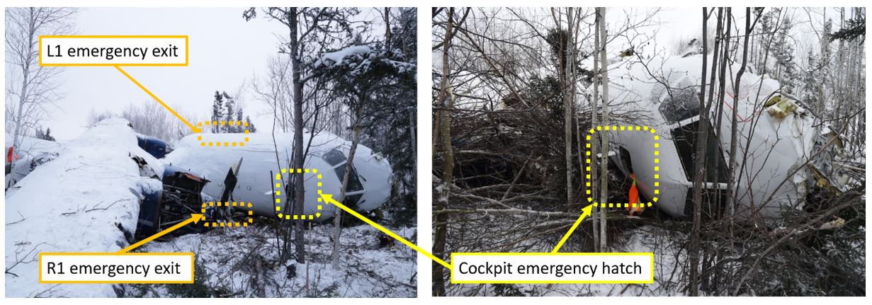
Because the main passenger cabin had rolled approximately 40° to the right, the service door (R2) was partially blocked by external terrain. The main exit point, the rear entry door (L2), was facing up, making it difficult to be opened (Figure 29).

1.15.5.5 Equipment, cargo, and other large masses
The current design standards for transport category aircraft require that equipment, cargo in the passenger compartment, and any other large masses must be positioned so that, if they come loose, they will be unlikely to prevent the use of any of the escape facilities.Footnote 82,Footnote 83
However, when the ATR 42 was certified, this requirement was not as restrictive, and the standard in place at the time only required that the
supporting structure must be designed to restrain, under all loads up to those specified in paragraph (b)(3) of this section, each item of mass that could injure an occupant if it came loose in a minor crash landing.Footnote 84
The cabin area of the aircraft was divided by partitions. Some partitions divided the passenger cabin from the forward cargo hold and from the rear entry door (L2). Examination of the partitions in other West Wind ATRs showed that the partition fixtures varied from aircraft to aircraft. Some were attached by cargo poles and some by hinges. In all cases, it was observed that these partitions, along with the cargo poles, may be easily displaced by limited vertical forces. Some partitions were immediately in front of the emergency exits.
During the accident sequence, many of the partitions became dislodged. The partition that separated the forward cargo area from the passenger cabin had dislodged and fallen into seats 1A and 1B, blocking access and identification of the L1 emergency exit (Figure 30).

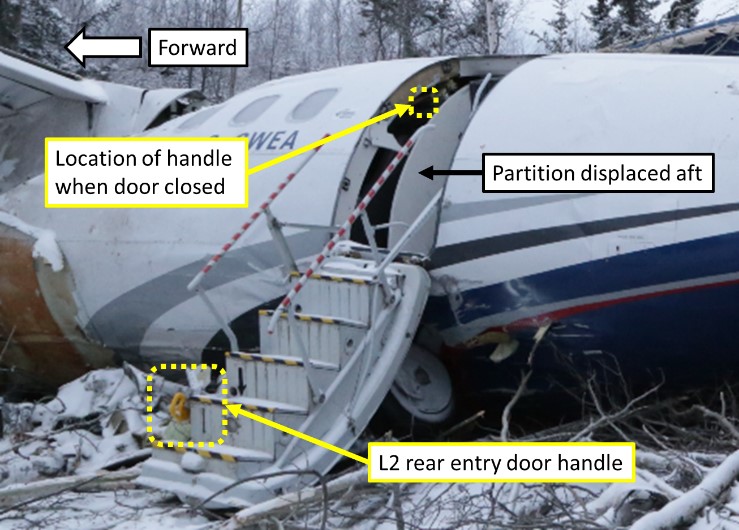
The partition that separated the passenger cabin from the rear entry door (L2) was also dislodged and fell across the door, blocking access to the door handle, which was on the other side of the partition (Figure 31).
In the forward cargo hold, immediately outside the cockpit door, cargo was secured with cargo nets, which were hooked onto vertical cargo poles. These cargo poles were latched into the aircraft structure. During the accident, the cargo poles became dislodged, and, although the nets remained attached, the luggage that was retained by the poles and nets came loose. The loose luggage and the dislodged poles and nets blocked the cockpit door, preventing egress from the cockpit into the main cabin of the aircraft (Figure 32).
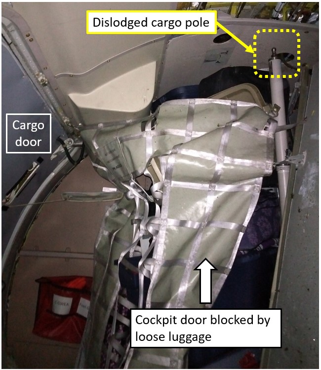
1.15.6 Post-impact survival factors
1.15.6.1 Environment
During the accident sequence, the aircraft cabin was breached by several tree branches, metal beams, panels, and other structural hazards. This exposed the occupants to the −10 °C ambient external temperature and it was dark and there was no available light.
Fuel leaked into the cabin and soaked the passengers; some got it in their eyes, affecting their vision. Some passengers were covered in blood, and some had lost their glasses. All passengers were injured, and most were trapped to some degree. Because of the angle of the aircraft, those on the right side were pushed into the intruding aircraft wall and those on the left side were crushed and/or hanging sideways in their seatbelts. Some passengers were partially inverted.
1.15.6.2 Aircraft evacuation
Figure 33 shows the methods of egress for all aircraft occupants. More details on the evacuation of the aircraft are provided in the following sections.
![Seating plan of occurrence aircraft showing locations of injured passengers and methods of egress for all aircraft occupants (Source: Avions de Transport Régional, Cabin Crew Operating Manual, Revision no. 4 [April 2018], with TSB annotations)](/sites/default/files/eng/rapports-reports/aviation/2017/a17c0146/images/a17c0146-figure-33.jpg)
1.15.6.2.1 Cockpit
The FO was able to free himself from the right-hand seat. He assessed the normal exit route through the cockpit but found it was blocked by luggage that had become loose in the main cargo area.
The FO then freed the captain from the left-hand seat and opened the emergency cockpit hatch, because this was the only viable evacuation route. The FO evacuated through the cockpit hatch, and the captain was extracted through the cockpit hatch with help from the FO and other outside responders.
1.15.6.2.2 Cabin
The collapse of parts of the cabin floor on impact, followed by a subsequent aircraft fracture and rotation, resulted in several factors that significantly impeded the evacuation.
Once the aircraft came to rest, the FA was able to free herself from under the broken seat and attempted to check the outside conditions, in accordance with her FA training. However, it was dark both inside and outside. With the aircraft on its right side, the right windows were facing the ground and the left windows were facing up.
Due to the transverse fracture, communication from the cabin to the cockpit was disabled, and the FA was unable to communicate with the flight crew. Therefore, she initiated an evacuation of the passengers.
The FA reportedly attempted to turn on the emergency lights, but the lights did not activate. Later examination of the emergency lights switch on the FA panel found that it was not depressed. The floor photo-luminescent strips were not visible or useful because the aisle had deformed and collapsed during the impact sequence.
Because there was no cabin lighting, the FA requested a cellphone from one of the passengers to use as a light. By this point, other passengers were also turning on their cellphone lights.
The FA attempted to open the rear entry door (L2) to evacuate the aircraft; however, the door handle was blocked by the adjacent partition that had been dislodged from its position. In addition, because the aircraft was positioned at an angle to the right, the rear entry door was above the occupants’ heads, making operation difficult in terms of reach and strength, even if the handle had been accessible.
Furthermore, there was no way to evacuate through the front of the aircraft, because the cabin and aisle had been crushed inwards. The FA and able-bodied passengers attempted to open the service door (R2), which was the only remaining accessible emergency exit; however, because the aircraft was lying on its right side, this door was partially blocked by external terrain. Passengers and the FA had to kick the door for several minutes before it eventually opened.
Fifteen passengers climbed out of or over seats to evacuate via the service door (R2). Some of those trapped in the middle of the aircraft had to remove outer clothing to get through the remaining gap of 1 to 2 feet leading to the rear exits. Some passengers, including the infant, had to be freed by other passengers before they could evacuate.
One passenger was ejected out of the transverse fracture during the initial impact sequence and 2 passengers seated in the front left side of the aircraft evacuated through the fracture.
It took approximately 20 minutes for the first 17 passengers to evacuate the aircraft. Some passengers evacuated but then re-entered the aircraft to help free other passengers. Three passengers remained trapped in the aircraft, and 1 passenger stayed to provide comfort. The last passenger was removed from the wreckage 3 hours after the accident.
1.15.6.3 Emergency response
The aircraft came to a stop at 1812:56. The wreckage was in a wooded area, approximately 600 m from the departure end of Runway 28. This location was close enough to the community that cellular service was still available.
Shortly after the end of the impact sequence and before the evacuation, passengers used their cellphones to request help by calling, texting, or sending social media messages. The FA borrowed a passenger’s cellphone to call 911.
Local people received the messages and calls that were made within minutes of the impact. Responders included family members, the 4th Canadian Ranger Patrol Group – Fond du Lac, community members, airport employees, and an airport contractor. All responders quickly set out to locate the aircraft and help in any way they could.
Because the initial information about where the aircraft went down was not clear, there was a delay before rescuers could find the accident site. Once the wreckage had been located, as more community members arrived, they were tasked with getting help, equipment, supplies, and directing rescuers to the site.
The site was dark, and the terrain was covered in snow. There was no road, so access was only possible by snowmobile. As more responders arrived, some left to get more help and equipment, while others started to assist passengers and crew and to ascertain who still needed to be evacuated.
The airport contractor, once informed of the accident, went to the crash site with highway equipment to provide light and to assist with the evacuation.
1.15.6.4 Royal Canadian Mounted Police response
The RCMP received the first of multiple calls regarding the accident at approximately 1815 and proceeded to the airport and the crash site, arriving at approximately 1830. Several community members were already at work helping passengers exit the wreckage, evacuating passengers using toboggans as they became available.
An aircraft carrying additional RCMP personnel and medical resources to assist at the site departed CYSF at approximately 1935.
1.15.6.5 Rescue
Passengers who had evacuated and the passenger who had been ejected from the aircraft were transferred to the local Fond-du-Lac medical facility on toboggans and snowmobiles. Once there, they were triaged and medically evacuated, if required, to hospitals and clinics in Stony Rapids, Prince Albert, and Saskatoon, Saskatchewan.
The responders also worked to free the passenger trapped on the right side, in seat 4D. This passenger was protruding out of a hole on the right side of the aircraft and, after approximately 1 hour, was extracted through the hole after responders had enlarged it using tools and their hands.
Responders then used equipment to free the trapped passengers in seats 5B and 6A. This extraction was difficult because every effort to free the passenger in seat 6A affected the passenger in seat 5B. Because of the fuel spilled and the risk of fire, it was impossible to use equipment to cut through the metal structures. Once it was available, responders used a hydraulic “jaws of life,” without having had any extraction training, to prise the seats and structure apart enough to free the passengers.
The passenger in seat 6A was extracted after approximately 1.5 hours. The passenger in seat 5B was extracted at around 2120, just over 3 hours after the crash.
1.16 Tests and research
1.16.1 TSB laboratory reports
The TSB completed the following reports in support of this investigation:
- GR301/2017 – Flight Recorders Group Report
- GR021/2018 – Site Survey
- GR028/2018 – Power Plant Group Report
- GR030/2018 – Photo/Video Group Report
- GR232/2018 – Structural Examination
- LP022/2018 – NVM Data Recovery
- LP008/2019 – Aircraft Ground Icing Analysis
1.17 Organizational and management information
1.17.1 Transport Canada
1.17.1.1 General
TC’s vision is to have a transportation system “that is recognized worldwide as safe and secure, efficient and environmentally responsible.”Footnote 85 For Transport Canada Civil Aviation (TCCA), that means “an integrated and progressive civil aviation system that promotes a proactive safety culture.”Footnote 86 One of the main tools TC uses to promote a safe and secure transportation system is oversight.Footnote 87
1.17.1.2 Organizational structure
TC carries out its civil aviation responsibilities through the Civil Aviation Directorate in Ottawa, Ontario, and its 5 regional Civil Aviation branches at offices across the country. Each of these offices is responsible for overseeing TC’s Civil Aviation Program in their respective region.
1.17.1.3 Evolution of oversight
TC defines oversight as “[a]ctivities that support the systematic promotion, monitoring, or enforcement of compliance with Transport Canada requirements governing safety or security and that contribute to departmental strategic outcomes.”Footnote 88
In 2005, TC made a shift to a new approach to its oversight functions with the introduction of safety management systems (SMS).Footnote 89 Since that time, there has been a significant change in the way TC conducts oversight of civil aviation in Canada.
Traditional oversight was largely composed of audits and inspections aimed at ensuring regulatory compliance. This approach, however, is only a first step, as ensuring compliance with regulations alone does not assure the regulator that identified problems will not recur. TC has therefore moved toward a systems approach to oversight whereby, in addition to verifying a company’s regulatory compliance, TC examines its internal processes to verify that the organization has an effective system to manage the risks associated with its operations.
To develop a regulatory environment conducive to the successful implementation of SMS, TC has translated its philosophy of greater cooperation into policies and procedures that favour the use of an operator’s safety management processes to address issues over the use of punitive sanctions. For example, Civil Aviation Directive (CAD) 107-004 states the following:
Transport Canada agrees to promote voluntary compliance with regulatory requirements, without necessarily resorting to punitive action, by providing certificate holders governed by an SMS, the opportunity to determine, by themselves, proposed corrective measures to prevent recurrence of a contravention, as well as the best course of action to help foster future compliance.Footnote 90
1.17.1.4 Transport Canada’s approach to surveillance
Since this accident, TC has initiated a number of changes to its surveillance policies and procedures. Due to the scope of this investigation, the report will focus primarily on the policies and procedures in place leading up to the accident.
Regulatory oversight requires the regulator to determine what surveillance activities will be carried out, to conduct surveillance activities, and to follow up to verify that identified deficiencies have been addressed. The sections that follow describe TC’s approach to the planning, conduct, and follow-up of oversight, including the guidance material used by inspectors in each phase—and how that approach evolved during the period leading up to and following the occurrence.
1.17.1.4.1 Surveillance planning
In Issue 06 of TC’s staff instruction (SI) SUR-001, which was in effect at the time of the occurrence, surveillance is defined as “all activities directly related to TCCA evaluating an enterprise’s compliance with applicable regulatory requirements including assessments, program validation inspections and process inspections.”Footnote 91
TC surveillance of an operator may be a planned activity based on predetermined intervals and an approved surveillance plan, or an unplanned activity in response to an unforeseen occurrence (accident, incident, or increase in operator risk indicatorsFootnote 92 [see section 1.17.1.4.2 National Aviation Safety Information Management System]).
In 2009, TC published Issue 01 of Civil Aviation Directive (CAD) SUR-008, establishing the following baseline surveillance intervals for all enterprises that are issued a TCCA certificate:
- Assessments (for SMS enterprises) will be conducted at 36-month intervals unless specific risk indicators indicate that a shorter cycle should be applied.
- Program validation inspections (PVIs) (SMS and non-SMS enterprises) will be conducted at 12-month intervals unless specific risk indicators indicate that a shorter cycle should be applied.Footnote 93
On 29 May 2012, TC published Issue 02 of CAD SUR-008, describing TC’s new risk-based approach to determining surveillance intervals for all companies, whether or not the companies have an SMS.Footnote 94 According to the revised guidance, “surveillance intervals shall range from 1 year (high risk and/or high impact enterprises) to 5 years (low risk and/or low impact enterprises).”Footnote 95
This change in surveillance intervals differs significantly from the recommendations laid out in ICAO’s Manual of Procedures for Operations Inspection, Certification, and Continued Surveillance, which states that “all significant aspects of the operator’s procedures and practices should be evaluated and appropriate inspections, commensurate with the scale of the operator’s activities, conducted at least once every 12 months.”Footnote 96 In addition, ICAO’s Safety Oversight Manual states that “Scheduled inspections must be augmented by periodic random inspections of all facets of the operation.”Footnote 97
1.17.1.4.2 National Aviation Safety Information Management System
According to TC’s surveillance planning policy at the time of the accident (i.e., CAD SUR-008), surveillance intervals were subject to an annual review and were determined using the following 2 criteria:
- Risk-indication level: This is a number from 1 (little to no risk) to 5 (significant risk). The elements considered in determining this rating are the National Aviation Safety Information Management System (NASIMS) risk-indicator number (RIN), the results of the most recent surveillance activity, the availability of safety information, and whether the company has an SMS.
- Impact-value determination: This is a rating from A (negligible impact) to E (extensive impact) that takes into account the number of certificates held, number of employees, bases, aircraft types, type of operations, and whether the operator conducts international operations.Footnote 98
At the time of the accident, the primary tool TC used to prioritize surveillance activities was the NASIMS. NASIMS was the result of a 2007 TC working group comprising various technical specialties formed “to develop a comprehensive risk indicator program.”Footnote 99
The NASIMS risk-indicator module consists of 77 close-ended questions pertaining to 10 key hazard areas. Each question is responded to with yes, no, or unknown, and comments can be added with a justification. According to SI SUR-005 Issue 01, “[q]uestion responses must be updated as new safety intelligence is received. This provides a near real-time risk picture […] .”Footnote 100
The responses are analyzed to calculate an operator’s RIN. Each year, TC reviews the surveillance intervals to prioritize its surveillance activities for each upcoming year.Footnote 101 In addition to the annual review, these surveillance intervals may be adjusted at any time if TC determines that such adjustment is warranted by changes in an operator’s risk indicators. However, there are no pre-set thresholds that automatically trigger such action.
On 01 April 2019, TC discontinued using the risk indicator module of NASIMS, which produced the RIN TC used to support the creation of the national surveillance plan. According to TC, the one-size-fits-all approach to risk-based surveillance planning created distortion in the national surveillance plan at the 2 extremes of enterprise complexity scales.Footnote 102
One of the reasons identified by TC to discontinue the use of the NASIMS was that the “quality of the data contained in NASIMS did not always reflect the current risk level present in the enterprise at the time the annual surveillance plan was created [...]. [C]onstant reminders had to be issued for the inspectors to populate the database.”Footnote 103
Some of NASIMS’ other functions are still in use at the time of writing of this report; however, TC is looking for a new solution based on business intelligence principles to replace NASIMS. At the time of report writing, TC had reverted to using peer groups and local intelligence, as detailed in SI SUR-028, for surveillance planning in fiscal year 2019–20, until a new system is in place and operational in 2 to 5 years.Footnote 104
1.17.1.4.3 Conduct of surveillance
Under section 8.7(1)(a) of the Aeronautics Act, the Minister of Transport has the authority to conduct inspections to monitor compliance with the Act.
As a result of TC’s shift to a systems approach to oversight, traditional audits and inspections have been replaced by system-level and process-level surveillance tools. These tools are intended to allow TC’s surveillance “to evolve beyond compliance auditing to include the review of an enterprise’s systems to determine if they are effective at achieving compliance both currently and on an on-going basis.”Footnote 105
SI SUR-001 describes each of these surveillance tools in detail. SI SUR-001 has undergone multiple revisions since its inception in 2005. At the time of the occurrence, SI SUR-001 Issue 06, issued on 22 June 2016, was in effect.
1.17.1.4.4 Surveillance findings
According to SI SUR-001, a finding is “a factual account, supported by evidence, of how an enterprise is not in compliance with regulatory requirements.”Footnote 106 In the contemporary system-based surveillance model, TC inspectors are required to write findings (stand-alone or system-level) against failures (i.e., non-compliance with regulations), and they must be documented using a standardized finding form. The finding form identifies the regulation(s) not being complied with, as well as examples that demonstrate the non-compliance.
SI SUR-001 requires that the surveillance team ensure that they have sufficient evidence to support their observations and any issues of non-compliance before they issue a finding.Footnote 107 This means that a finding must be supported by sufficient specific and factual evidence that clearly shows how it resulted in the operator being non-compliant with the regulations. If there is not enough evidence to support a finding, further sampling must be conducted.Footnote 108
At the time of the accident, findings of non-conformance identified during systems-level surveillance activities were classified as shown in Table 5 .Footnote 109
| Classification | Criteria |
|---|---|
| Minor | A finding is considered minor where a surveillance activity has identified that the area under surveillance has been maintained and demonstrated to be effective; however, it requires administrative enhancement. |
| Moderate | A finding is considered moderate where a surveillance activity has identified that the area under surveillance has not been fully maintained and examples of non-compliance indicate that it is not fully effective; however, the enterprise has clearly demonstrated the ability to carry out the activity and a simple modification to their process is likely to correct the issue. |
| Major | A finding is considered major where a surveillance activity has identified that the area under surveillance has not been established, maintained and adhered to or is not effective, and a system-wide failure is evident. A major finding will typically require more rigorous and lengthy corrective action than a minor or moderate finding. |
Enterprises are required to submit corrective action plans (CAPs) to TC when findings are generated during a surveillance activity. These CAPs, which must be accepted by TC, outline how the enterprise plans to address the regulatory non-compliance and ensure ongoing compliance in the future.
According to SI SUR-001, assessments and PVIs must be closed within 12 months of CAP acceptance.Footnote 110 To facilitate this timetable, “the CAP shall aim at having all corrective action in place within 90 days of acceptance by the applicable inspector.”Footnote 111
In some cases, it may take longer than 90 days to implement long-term action items. If a CAP will take more than 90 days but less than 1 year to complete, TC must decide whether it is acceptable, and that decision must be documented.Footnote 112 SI SUR-001 also recommends that a risk assessment be considered before acceptance; however, it is not mandatory. When CAP completion will take more than 1 year, the decision must be escalated to TC regional management and the National Civil Aviation Management Executive Committee (NCAMX)Footnote 113 for review and decision.Footnote 114
1.17.1.4.5 Assessments and program validation inspections
TC expects companies to proactively manage safety, and to ensure that risks are managed to acceptable levels. TC also expects companies to have programs in place to ensure continued compliance with regulatory requirements.Footnote 115 The 2 primary systems-level surveillance tools that TC uses to ensure these expectations are met are assessments and PVIs.
According to SI SUR-001, an assessment evaluates the effectiveness and the ability of the enterprise’s SMS to maintain compliance with the CARs. TC uses its SMS Framework (Appendix A), which outlines the components and elements of an SMS, when conducting an assessment.
While an assessment involves looking at the SMS components and elements, a PVI is “a process comprised of research and on-site review of one or more components of a SMS or other regulated areas of an enterprise.”Footnote 116 Assessments and PVIs are conducted at intervals based on risk indicators described earlier in this report (i.e., from 1 to 5 years).
According to SI SUR-001, the overall procedures are the same for assessments and PVIs. The only differences are the timeline—due to the difference in scope—and the focus of the surveillance.Footnote 117 A PVI is not as in-depth as an assessment; therefore, it typically takes considerably less time to complete.
For assessments and PVIs, the Regional Director of Civil Aviation designates a convening authority (CA)Footnote 118 who assembles a team and designates a manager to oversee the activity. The team typically consists of civil aviation inspectors in areas of flight operations, airworthiness, and cabin safety, as well as administrative personnel.
1.17.1.4.6 Process inspections
A process inspection (PI) is “an in depth review of an enterprise process utilised to produce an output to verify whether it functions or not.”Footnote 119 Unlike assessments or PVIs, a PI looks at a single process within an enterprise to verify whether regulatory requirements are being met and to ensure that the process is functioning as intended. Any process required by regulation may be the focus of a PI.
According to SI SUR-001, “a process inspection shall only be conducted for cause.” Footnote 120 For example, SI SUR-001 states that PIs may be used for several reasons, including:
- in response to an event or change in risk indicator within an enterprise;
- in support of a systems level surveillance activity;
- to gather safety intelligence; or
- as a scheduled surveillance activity, for example to supplement planned surveillance intervals.
When conducted as a stand-alone surveillance activity, the results of a PI can also result in initiating, or accelerating timelines for, a systems-level surveillance activity.Footnote 121
Much like an assessment or a PVI, a PI can generate findings; however, those findings are not assigned a classification. Findings resulting from a PI must be addressed using a CAP.Footnote 122 Timelines for a PI CAP are the same as described for PVIs and assessments. SI SUR-001 does not specify a closure time for PIs.
The PI report must indicate whether the process meets applicable regulatory requirements and is being followed as published in approved operator manuals, or whether the process is not documented, implemented, or effective.
1.17.1.4.7 Follow-up
SI SUR-001 identifies 4 processes that can be used in response to issues of non-compliance detected during surveillance activities.Footnote 123 These processes are, in increasing order of severity,
- CAP;
- enforcement action;
- enhanced monitoring; and
- certificate action.
Corrective action plan
In line with TC’s cooperative approach to oversight, if issues of non-compliance are found during a surveillance activity, operators are given the opportunity to provide CAPs to rectify the deficiencies. A CAP “outlines how the enterprise proposes to address identified regulatory non-compliances and ensure on-going compliance.”Footnote 124 CAPs are required by TC policy rather than by regulation.
SI SUR-001 states that CAPs must be submitted for each finding and within 30 days of receipt of the report of non-compliance, unless there are extenuating circumstances and TC approves an extension.Footnote 125
The CAPs must be completed in accordance with Advisory Circular (AC) SUR-002 and submitted to TC for acceptance.Footnote 126 AC SUR-002 explains that CAPs must identify the reasons underlying the deficiency and include an action plan to address them. In contrast to SI SUR-001, AC SUR-002 does not specify a requirement to submit CAPs within 30 days of receipt of the report.
TC inspectors are responsible for assessing whether CAPs are acceptable, selecting either administrative or on-site follow-up to verify implementation of the CAP, and proposing a date for the follow-up selected. If CAPs are rejected, they are returned to the operator for revision, and the operator then has 7 days to re-submit the revised CAP.Footnote 127 If the revised CAP is rejected, SI SUR-001 indicates that the CA must be informed and that the CA will then determine the most appropriate course of action. According to SI SUR-001 section 12.3.4, the CA may select any 1 or combination of
- another opportunity for the enterprise to revise the CAP;
- enforcement action; or
- certificate action.
Enforcement action
When TC determines that a finding warrants some type of enforcement action (i.e., administrative or monetary penalties), a detection noticeFootnote 128 must be submitted to TCCA Aviation Enforcement.
According to SI SUR-001, “CARs cited within the detection notice shall be offence creating [sic] provisions, whether they serve as the basis of the finding or quoted within the examples of the finding.”Footnote 129 The detection notice, associated finding(s), and any supporting evidence are then forwarded to TCCA Aviation Enforcement for action/follow-up, in accordance with the Enforcement Procedures Manual.Footnote 130
When a detection notice is submitted, TCCA Aviation Enforcement ensures that the condition that led to the enforcement action no longer exists so that the surveillance activity can be closed. This is performed via the CAP process.
Enhanced monitoring
The third option presented in SI SUR-001 for follow-up on issues of non-compliance is enhanced monitoring (EM). If EM is the chosen follow-up process, SI SUR-001 directs that it must be conducted and closed in accordance with SI SUR-002.
EM is used when a company’s compliance and/or safety record indicates that an increased TC presence is necessary to return the operator to a state of compliance and to gain confidence that the operator can maintain compliance with regulations. According to SI SUR-002, EM is used either when “major findings of systemic failures”Footnote 131 leading to non-compliance have been identified during an assessment or PVI, or there is a history of non-compliance or a failure to demonstrate an ability to comply with regulations.Footnote 132
The 2 goals of EM are
- [t]hat the enterprise develops and implements measures to deal with its non-compliances, ensuring compliance with regulations during and after the period of EM; and
- [t]hat TCCA takes a comprehensive look at the operator’s systems, through increased regulatory surveillance activities, in order to confirm the operator’s ability to maintain compliance with applicable regulations.Footnote 133
When EM is to be conducted, the CA appoints an EM manager, who develops a plan for the EM. SI SUR-002Footnote 134 lists a number of elements that must be included in the EM plan:
- Team roles/responsibilities
- Communication protocols
- Activities that are to take place
- Timeframes
- Conditions for termination of EM
- Budgetary details
- Administrative details relevant to EM
The EM team members are responsible for completing and documenting assigned EM activities and for providing updates to the EM manager.
According to SI SUR-002, EM must be composed of the following:
(a) A verification period of a maximum of 90 days following CAP acceptance during which EM team members verify that the enterprise has implemented corrective actions; and
Note: It is acknowledged that certain long term corrective actions may take longer than 90 days to implement. However, at a minimum a state of compliance must be verified to have been reached by the enterprise during the 90 day verification period.
- (b) An EM terminating PVI within 12 months of initiation of EM, conducted in accordance with SI SUR-001 that, at a minimum, covers the same areas that led to the initiation of EM.Footnote 135
According to SI SUR-002, if an enterprise has not implemented corrective actions effectively by the end of the verification period, an EM-terminating PVI will be commenced so that appropriate action can be taken.
When an EM-terminating PVI is conducted, the CA must document any decision to take action, along with the process used to arrive at the action. If there are no findings, or only minor findings that the company subsequently corrects, the company returns to its routine surveillance schedule and the EM is closed. If there are moderate and/or major findings, the CA determines the most appropriate course of action, on a case-by-case basis, in consultation with TCCA regional/headquarters management and enforcement personnel.
Since “EM is not intended to be a perpetual state in which an enterprise operates,”Footnote 136 if the EM-terminating PVIFootnote 137 determines that the enterprise is not ready to return to routine monitoring, it may be subject to another round of EM. Unless authorized by a Regional Director of Civil Aviation or a director at TC headquarters, an enterprise can only undergo EM twice in succession.Footnote 138
Without this authorization, the failure of a second EM-terminating PVI results in certificate action, in accordance with SI SUR-014.Footnote 139
The investigation determined that TC personnel from the Prairie and Northern Region, at both the operational and management level, were uncertain of specific steps and timelines associated with EM. The EM guidance provided to regional personnel is largely in text format and does not include clear decision-making or planning tools such as flow charts, timeline templates, or specific checklists to follow to ensure EM is conducted in accordance with national policy.
Certificate action
When certificate action is selected as a follow-up process, it must be conducted in accordance with the provisions of SI SUR-014. This SI applies to TC inspectors delegated to act on behalf of the Minister of Transport for issues related to safety, in relation to subsection 7(1) (immediate threat to safety) and subsection 7.1(1) (other grounds) of the Aeronautics Act.
These delegates (acting on behalf of the Minister) may take certificate action under section 7.1 of the Aeronautics Act for the following reasons:
- Incompetence: SI SUR-014 defines incompetence as the “inability to perform activities that are authorized in a [Canadian Aviation Document] in compliance with the regulations and standards applicable to that type of activity.”Footnote 140 It also states that certificate action based on incompetence is applicable only to individuals and not to organizations.
- Cessation of meeting qualifications: Certificate action under this section of the Act is appropriate when an operator no longer meets the qualifications required for the certificate to be issued.Footnote 141
- Public interest: This category is used “when past non-compliance is serious and repeated enough to conclude that there is a risk of further offences.”Footnote 142 In pursuing certificate action under this section of the Act, SI SUR-014 states that it would be appropriate to consider records, including accident records; compliance records (Aviation Enforcement Division records); and audit, PVI or assessment records related to system compliance.
In 2013, TC issued internal process bulletin (IPB) 2013-02 to provide additional direction for taking certificate action. The IPB noted that some inspectors believed that they did not have the appropriate tools to take certificate action when it is warranted. IPB 2013-02 stated that, when inspectors select certificate action, “functional guidance to support the selection is available from the Standards Branch.”Footnote 143
Further to IPB 2013-02, in 2015, TC issued IPB 2015-03 to provide an overarching policy on certificate action within TCCA. In the graduated approach section of the IPB, it stated that the decision to take certificate action should be based on several factors, including the enterprise’s safety record, the number of findings, the classification of findings, the enterprise’s compliance history, and its ability to produce a CAP.Footnote 144 Specifically, it stated that the greater the number and classification of findings, the more severe the follow-up action. However, IPB 2015-03 did not provide any further guidance to determine the most appropriate follow-up action.
Several TC inspectors that were interviewed during this investigation indicated that they perceived that the graduated-approach policy meant that enforcement and/or certificate action could only be taken once all attempts at the CAP process had been exhausted. This is also consistent with SI SUR-001 Issue 06, which stated that “the CAP process should be considered first, followed by Enforcement Action, then Enhanced Monitoring, and finally Certificate Action.”Footnote 145
The investigation also determined that several of the regional TC inspectors involved in a 2016 assessment of West Wind (see section 1.17.1.7.6 Assessment of West Wind (September 2016)) believed that detection notices (i.e., enforcement action) could not be filed against an SMS enterprise unless that enterprise had first been given the opportunity to address the issues of non-conformance via the CAP process.
1.17.1.5 Dissemination of policies and procedures at Transport Canada
When a new document is issued or a new issue of an existing document is released, it is made available to all TCCA staff as follows:
- It is added to the Civil Aviation Document Collection.
- It is made available via TC’s “myTC Oversight” app.
- It is mentioned in a monthly email sent to all personnel informing them of new publications on those platforms.
TC does not have a process to ensure that inspectors read or review newly issued or updated publications. Instead, the onus is on the inspectors to do so.
The investigation determined that inspectors routinely refer to the latest SI that is effective; however, they do not normally review the supporting documents, which may supplement the material in the SI. In addition, inspectors typically do not review newly released publications unless they become aware that they are pertinent to the inspectors’ activities.
1.17.1.6 Transport Canada’s efforts to improve oversight of commercial aviation
1.17.1.6.1 General
Since 2015, TC has undertaken a number of initiatives to improve the oversight of commercial aviation in Canada. Some of those initiatives are briefly described below.
1.17.1.6.2 Transport Canada’s Civil Aviation Transformation project
In 2015, TC’s Civil Aviation Transformation project identified national oversight as one of several areas requiring action. To address concerns about TC’s national-level oversight of its surveillance program (also identified by the TSB),Footnote 146 TC established a National Oversight Office (NOO) and an Oversight Advisory Board (OAB).
1.17.1.6.3 National Oversight Office
The NOO was established in 2015 to assist with managing the way safety oversight is delivered and monitored. The NOO facilitates discussion with management on a monthly basis to review national and regional oversight risks related to industry performance and compliance as well as oversight delivery performance. This provides a platform for decision making on issues related to complex oversight matters as well as continuous monitoring of enterprise performance and compliance.
1.17.1.6.4 Oversight Advisory Board
The OAB was created to provide “support and recommendations to operational branches for addressing concerns and processing complex oversight decisions rapidly, effectively, and consistently allowing operational branches to take timely action against certificate holders that are not operating within regulatory requirements.”Footnote 147
Before the creation of the OAB, TC regional offices operated largely in isolation when it came to selecting the most appropriate method for addressing issues of non-conformance identified during surveillance activities. As a result, there was considerable variation among how the national standards were being applied across the country.Footnote 148
The OAB activities began in 2015 and, on 16 March 2016, TC issued IPB 2016-04 to communicate temporary changes to SI SUR-001, SI SUR-002, and SI SUR-014 and to provide the process to follow and criteria for when to engage the OAB.
IPB 2016-04 states that operational branches must invoke the OAB, by submitting a TCCA OAB issue report to the NOO, under the following circumstances:
- Issues of non-compliance and decisions pertaining to enhanced monitoring involving high profile enterprises
- Enterprises with any combination of:
- Multiple/major findings
- Repeat findings/non-compliance
- Ineffective correction actions
- Impact to the public or Minister
- Certificate actions that may significantly impact the public or public confidenceFootnote 149
IPB 2016-04 also encourages operational branches to consult the NOO for guidance on applying the criteria above.
In October 2017, TC issued SI SUR-027, formalizing the OAB and outlining its role. In May 2020, TC released SI SUR-027 Issue 02 which incorporated, and therefore cancelled, IPB 2016-04.
1.17.1.7 Transport Canada’s oversight of West Wind Aviation
1.17.1.7.1 Assessment of West Wind (18–22 January 2010)
In January 2010, TC conducted an assessment of West Wind’s recently implemented SMS.Footnote 150 The assessment resulted in 13 minor and 6 moderate SMS component-related findings. Furthermore, the assessment report stated that West Wind’s risk management program (i.e., SMS component 3.4 – Risk Management) did not meet the following minimum regulatory requirement:
There is a structured process for the management of risk that includes the assessment of risk associated with identified hazards, expressed in terms of severity and probability of occurrence and where applicable the level of exposure.Footnote 151
The assessment determined that “West Wind Aviation Limited’s SMS does not fully meet applicable regulatory requirements for a system that is documented, implemented, in use and effective.”Footnote 152 West Wind was required by TC policy to produce CAPs to address the assessment findings, and on 13 October 2010, TC advised West Wind that all corrective action and follow-up had been completed and that the assessment was considered closed.Footnote 153
Following the 2010 assessment, TC considered West Wind to be an SMS enterprise; however, TC was unable to provide any documentation showing that West Wind met all the requirements, per the regulations, to have SMS enterprise status.
1.17.1.7.2 Program validation inspection (07–11 March 2011)
From 07 to 11 March 2011, TC conducted a PVI of West Wind. The stated purpose was “to verify that the organization has an effective Quality Assurance Program and Operational Control System.”Footnote 154
The resulting PVI report stated, “Your organization has demonstrated that the areas of both Quality Assurance and Safety Oversight did not conform to the minimum Regulatory requirements as set out in CAR 107.03.”Footnote 155 The report identified 6 findings of non-conformance, consisting of 3 classified as minor and 3 as moderate. The 2011 PVI findings were dealt with via CAPs that were implemented and closed in a timely manner. On 16 January 2012, TC informed West Wind that all corrective action and follow-up were completed and that the PVI was considered closed.
1.17.1.7.3 Program validation inspection (21–24 February 2012)
From 21 to 24 February 2012, TC conducted a PVI of West Wind. The stated purpose was “to verify that the organization has an effective Quality Assurance Program and Safety Oversight System.” As in the 2011 PVI report, the 2012 PVI report stated, “Your organization has demonstrated that the areas of both Quality Assurance and Safety Oversight did not conform to the minimum Regulatory requirements as set out in CAR 107.03.”Footnote 156 However, the TC report did not include findings specifically related to West Wind’s internal safety oversight. The report contained 5 findings, 1 classified as minor, and 4 as moderate. The TSB was unable to confirm, with documentation provided by TC, that the 2012 PVI CAP had been verified through appropriate follow-up and that the PVI was considered closed.
1.17.1.7.4 Program validation inspection (21–25 January 2013)
From 21 to 25 January 2013, TC conducted a PVI of West Wind to “verify that the organization has an effective Quality Assurance Program and Safety Oversight System […] to determine the effectiveness of the company’s systems.”Footnote 157 The PVI team used Appendix B of SI SUR-001 to determine the degree of conformance to the CARs and approved company manuals/documents.Footnote 158 The January 2013 PVI resulted in 7 findings, consisting of 3 classified as minor, 3 as moderate, and 1 as major. The major finding was related to training, awareness and competence.
West Wind submitted a CAP to TC on 25 March 2013. On 27 August 2013, TC sent a letter to West Wind stating that “all corrective action and follow-up in regards to the PVI findings has now been taken; the PVI is considered closed.” Footnote 159
1.17.1.7.5 Routine surveillance (September 2013–August 2016)
From September 2013 to August 2016, TC conducted the following surveillance activities at West Wind:
- Administrative review of documents
- Approved check pilot (ACP) monitors
- Cabin safety in-flight checks
These activities are not governed by SI SUR-001.
During this 3-year period, West Wind was not subject to any additional surveillance activities such as assessments, PVIs, or PIs.
1.17.1.7.6 Assessment of West Wind (September 2016)
General
On 20 July 2016, the CA approved an assessment plan for West Wind, and a 12-inspector team was tasked to carry out an assessment, in accordance with SI SUR-001, from 29 August to 23 September 2016.
Assessment plan
The objective of the assessmentFootnote 160 was to evaluate West Wind’s SMS, including all components and elements; the aircraft maintenance organization; and elements related to the Air Operator Certificate, such as training, operational control, quality assurance, and the company’s ability to maintain compliance with the CARs.
On-site activities 12–16 and 19–23 September 2016
At the completion of the first on-site period from 12 to 16 September 2016, the assessment team identified several issues (Appendix B), including with the operator’s training documentation and noted that items from those training programs needed to meet the Commercial Air Services Standards (CASS) were missing.Footnote 161 As a result, 3 major on-site findings were issued detailing concerns with the company’s training programs.Footnote 162
On 16 September 2016, West Wind responded to on-site finding 01 with a short-term CAP. This short-term CAP, which TC accepted, resulted in West Wind grounding all ATR 42 pilotsFootnote 163 immediately until the identified issues with the company’s Subpart 705 ATR 42 training program were resolved. On 19 September 2016, West Wind’s ATR 42 flight crews were retrained and flight operations resumed.
West Wind also produced short-term CAPs for on-site findings 02 and 03, which TC accepted on 20 September 2016. As a result, the company voluntarily grounded its Subpart 703 and Subpart 704 operations until similar issues with these training programs were resolved.
On 19 September 2016, as stated in the surveillance report, “due to the significance and classifications of the non-compliances including the systemic failures of West Wind Aviation Limited Safety Management System,”Footnote 164 TC cancelled the remaining assessment activities. These planned activities included in-flight inspections, ramp inspections, and interviews.Footnote 165
On 21 September 2016, discussions took place at TC regarding the possible issuance of a notice of suspension (NOS) to West Wind, but an NOS was deemed counterproductive, because West Wind was working to address the on-site findings.Footnote 166 A decision was made to complete the findings and ensure all supporting documentation was obtained.
On 23 September 2016, the assessment team held an exit meeting with senior West Wind executives and managers. During the exit meeting, the team advised West Wind that the deficiencies identified could lead to enforcement action, EM, or certificate action.Footnote 167
Post-surveillance decision making
Within a couple of weeks of terminating the 2016 assessment, and due to the extent and severity of the findings, the CA decided that the company would be placed under EM.
At the time, the regional TC staff’s understanding of TC’s graduated approach did not allow for the issuance of an NOS to an SMS enterprise. It was the team’s understanding that an SMS enterprise had to be given the opportunity to address the identified areas of non-compliance via the CAP process. Likewise, there was no consideration given to engaging the OAB or the NOO, as team members were unaware of their existence, nor were they aware of or familiar with the contents of IPB 2016-04.
Assessment report
On 09 November 2016, the CA sent the assessment report to West Wind.Footnote 168 The report’s executive summary stated that, “as a result of this surveillance activity, West Wind Aviation Limited is being placed under enhanced monitoring”Footnote 169 in accordance with SI SUR-002. The report also stated that further details about the EM process would be forthcoming.
The 2016 assessment of West Wind resulted in 10 findings: 3 major findings that were issued on site, and 5 additional major findings and 2 moderate findings that were issued later (Appendix C).
The assessment report concluded that the company must submit CAPs to address all findings no later than 28 December 2016 and that TC would conduct further follow-up to ensure that the CAPs addressed the areas of non-compliance. The report also stated that the 3 on-site findings would be sent to TC Enforcement for further review and the other findings would be reviewed against the supplied CAPs to determine what, if any, further action would be required.
Follow-up of the September 2016 assessment
West Wind submitted CAPs for all the assessment findings within the prescribed time limit (i.e., within 30 days of receipt of the non-compliance report).
On 22 December 2016, TC advised West Wind that all CAPs had been accepted, and that on-site verification of CAP implementation and effectiveness would take place at an unspecified later date.Footnote 170 However, at the time of the accident (approximately 12 months later), some of the long-term CAPs had not yet been verified by TC.
1.17.1.7.7 Enhanced monitoring
On 12 December 2016, TC sent a letter to West Wind advising it again that the company would be under EM because of systemic issues of non-compliance identified during the assessment.Footnote 171
TC recorded that it conducted an EM entry meeting with West Wind management over the course of 2 days (20–21 December 2016);Footnote 172 however, TC was unable to provide the TSB with any documentation regarding the details of this meeting.
According to SI SUR-002, the EM surveillance manager must develop an EM plan. The TSB requested a copy of the West Wind EM plan from TC. However, TC was unable to produce any EM plan or a record that an EM plan had been considered for West Wind. TC was unable to provide a reason why a plan for EM of West Wind had not been developed.Footnote 173
From December 2016 to April 2017, as part of the EM, TC conducted several surveillance activities at West Wind that included monitoring training, reviewing quality assurance audits and SMS reports, and assessing the effectiveness of CAPs that resulted from the 2016 assessment.
In April 2017, the CA and the EM team reviewed the EM records and concluded that the company was unable to demonstrate that it had “the resources, ability or willingness to implement systemic changes required to comply with the applicable requirements.” As a result, in accordance with SI-SUR-002,Footnote 174 TC decided that West Wind was not ready to terminate EM and that EM would continue.Footnote 175
From April to December 2017, as part of the continued EM, TC conducted and documented a number of surveillance activities that took place during at least 17 separate visits to the operator. These activities included monitoring training and check rides, flight operations and cabin safety inspections, meetings with management, interviews with prospective management candidates, and document and process reviews.
At the time of the occurrence, West Wind had been under EM for almost 12 months; however, at no point during the EM was the OAB invoked or the NOO consulted with regards to how to best handle the oversight and monitoring of West Wind.
1.17.1.7.8 Post-occurrence process inspection and certificate suspension
As a result of the occurrence, on 18–20 December 2017, TC conducted a post-occurrence PI at West Wind headquarters. On 20 December 2017, TC issued an on-site major finding due to several areas of non-compliance related to CAR 705.02. TC concluded that there was a loss of operational control and suspected this also included the subparts 703 and 704 operations.
In response, West Wind temporarily ceased all airline operations (CARs Subpart 705) and, shortly thereafter, all operations (i.e., including CARs subparts 703 and 704), pending a full analysis of its systems and processes.
On 21 December 2017, the OAB convened to help determine the most appropriate course of action. Following these discussions, TC was of the opinion that an immediate threat to aviation safety existed because of a lack of operational control at West Wind, and that it was in the public interest to suspend West Wind’s air operator certificate.Footnote 176
On 22 December 2017, TC issued an NOS, effective immediately, to West Wind. The NOS cited the grounds for suspension, which included the following:Footnote 177
- Flight crews are not consistently performing daily aircraft safety checks.
- The operator did not effectively manage flying into possible known icing conditions for flights at remote locations.
One of the conditions for terminating the suspension listed on the NOS was for the operator to have a functioning SMS that meets the CARs requirements.
1.17.1.7.9 Surveillance planning for West Wind
To gain a better understanding of TC’s surveillance planning for West Wind, the investigation looked at the company’s NASIMS risk-profile scores and TC’s interpretation of those scores.
From June to November 2012, TC established a NASIMS baseline profile of West Wind using the 77 closed-ended questions to produce a RIN. Footnote 178 Based on the RIN and the risk-indicator level, West Wind’s surveillance-interval matrix value was rated as 2D, or low risk, high impact (Appendix D). According to CAD SUR-008, an SMS enterprise with a score of 2D is subject to a 4-year assessment interval; however, there is no requirement for planned PVIs. In light of the 2010, 2011, and 2012 findings of non-compliance at West Wind, the investigation sought to better understand the rationale behind the 2D rating, as TC was unable to provide such a rationale.
The investigation reviewed West Wind’s NASIMS risk profile (Appendix E). When a change in response is made to 1 of the 77 questions used to determine the company’s risk profile, the date of the change is indicated. If the response to the question does not change, the date of the last change remains. Of the 77 questions 55 responses were last changed in 2012, 7 were changed in 2013, none in 2014, 1 in 2015, 13 in 2016, and 1 in 2017.
This absence of timely updates to NASIMS was identified in a previous TSB accident investigation report. Footnote 179 Likewise, the 2012 Spring Report of the Auditor General of Canada highlighted that “the risk indicators that Transport Canada uses to identify the high-risk aviation companies that should be inspected is not always available or kept up to date.” Footnote 180
The NASIMS printout for West Wind for this time period also states that all responses were verified in 2013, 2014, 2015, and 2016; however, for the planning year 2013–14, the findings under “surveillance results” were incorrectly classified as moderate, and the major finding raised during the January 2013 PVI was not recorded as such. As a result of this error, West Wind’s risk-profile score kept the company at a 4-year surveillance interval. Had the major finding been correctly entered in NASIMS, the company would have been rated as 3E, which would have resulted in the company being subject to a 3-year PVI and 5-year assessment schedule.
For planning year 2017–2018, the surveillance-interval matrix value was increased to 4E in response to the 8 major findings identified during the 2016 assessment. This changed the company’s surveillance to a 2-year PVI and 4-year assessment schedule.
1.17.2 West Wind Aviation L.P.
1.17.2.1 General
West Wind was established in 1983. West Wind’s corporate offices and its main operating base are located in Saskatoon, Saskatchewan. Sub-bases are located in La Ronge and Stony Rapids, Saskatchewan. At the time of the occurrence, the company employed approximately 153 people, of whom 53 were pilots.
The organization provides both scheduled and non-scheduled domestic and international air transportation services for passengers and for all types of cargo, including dangerous goods. At the time of the accident, the company operated 5 ATR 42 aircraft under CARs Subpart 705, as well as several other aircraft types under CARs subparts 703 and 704.
1.17.2.2 Organizational structure
West Wind’s organizational structure is detailed in Figure 34. On the operational side of the structure, the 2 Chief Pilots both report directly to the Director of Flight Operations (DFO),Footnote 181 whereas the SMS Manager reports to both the DFO and Director of Maintenance.
![West Wind’s organizational chart (Source: West Wind Aviation L.P., West Wind Aviation 705 Operations Manual, Amendment 34 [21 December 2015])](/sites/default/files/eng/rapports-reports/aviation/2017/a17c0146/images/a17c0146-figure-34.jpg)
1.17.2.2.1 Personnel changes
Between 2010 and 2017, there were 7 personnel changes to the DFO position and 4 personnel changes to the Chief Pilot 703/704 position.
On 19 September 2016, the DFO assumed the additional role of acting Subpart 705 Chief Pilot, to replace an interim Chief Pilot who was retiring later that month. Shortly thereafter, the company completed an internal risk assessment to examine the risks of replacing the previous Chief Pilot, who had occupied that position for the past 13 years.
The risk assessment identified the risk of assigning the DFO to hold the Chief Pilot position until a permanent candidate could be found as “changes in management can result in a loss of operational control.” The risk was assessed as “low,” and a CAP was developed and accepted by the DFO.
The report outlined various risk controls related to the hiring of a new chief pilot; however, no risk controls were focused on the additional pressures on the DFO due to the increased workload associated with assuming the chief pilot duties, as this pressure was not specifically identified as a risk.Footnote 182
On 22 December 2016, TC approved the dual-role position of DFO and Subpart 705 Chief Pilot for a period of 1 year ending 01 January 2018.Footnote 183 By the end of December 2016, the DFO had taken on the Subpart 705 Chief Pilot roles and responsibilities. At the same time, the position of Director of Regulatory Standards and Compliance was eliminated at West Wind, and the duties assigned to this position were transferred to the DFO.
In the summer of 2017, the DFO announced his retirement effective 03 November 2017. Because this change could present a risk to operations, West Wind carried out a safety caseFootnote 184 in August 2017.Footnote 185 The safety case, which West Wind submitted to TC as part of the application/approval process for the appointment of a new DFO, identified several risk areas and control measures to reduce the risks associated with hiring a new candidate.
Following the departure of the DFO, and approximately 1 month before the accident, West Wind assigned different individuals to the Subpart 705 Chief Pilot and the DFO positions, putting an end to the dual role.
1.17.2.3 West Wind’s operations manual
West Wind policies common to all company flight operations are contained in the West Wind Aviation L.P. Operations Manual (COM). This manual is comprised of several parts: West Wind Aviation 705 Operations Manual, West Wind Aviation 703/704 Operations Manual, Flight Dispatch Operational Control Manual, and Flight Crew Training Manual.
The COM provides information required by the CARs and the CASS, and is intended to implement, and in some instances supplement, the requirements of the CARs and CASS. The West Wind COM and amendments were reviewed and approved by TC.
Flight operations staff are required to be familiar with the contents of the COM and to comply with its policies and procedures. Training provided by the company to its employees is required to cover the necessary information detailed in the company manuals, procedures, and TC regulations.
1.17.2.4 West Wind’s methods of monitoring flight operations
West Wind employed several methods to monitor flight crew performance and adherence to company policies and procedures, including:
- initial technical ground training, which provided an opportunity to indoctrinate pilots with the company’s operating philosophy, policies, and procedures (West Wind COM), AFM, FCOM, Quick Reference Handbook, and the West Wind ATR 42 standard operating procedures (SOPs);
- initial simulator training, in which pilots received training that reinforced the company’s operating philosophy, policies, and procedures;
- pilot proficiency checks, which were performance checks conducted in a simulator to verify that pilots had met the required standard and to validate the training process;
- line indoctrination, which was conducted by training pilots to expose pilots to the company’s operational environment and to further reinforce the company’s operating philosophy, policies, and procedures;
- line checks, which were conducted at the completion of line indoctrination to verify that pilots’ performance met the required standard;
- recurrent training, which involved annual ground and simulator training that provided opportunities to reinforce the company’s operating philosophy, policies, and procedures;
- recurrent pilot proficiency checks and line checks, which provided another opportunity annually for the company to verify that pilots met the required standard and to verify their compliance with company policies and procedures;
- line reports, which provided company management with a limited opportunity to monitor flight operations as reported by captains; and
- management flying, which involved company flight operations managers flying periodically with line pilots, and provided managers with an opportunity to directly observe pilot performance.
1.17.2.4.1 Flight data monitoring
Flight data monitoring (FDM) is a program to improve flight safety by providing more information about, and greater insight into, the total flight operations environment through selective automated recording and analysis against objective data generated during flight operations. FDM is also known as flight operational quality assurance (FOQA) or flight data analysis.
An FDM program is intended to enable an operator to identify, quantify, assess, and address operational risks through discreet and anonymous collection of electronic flight data from routine operations. Proactive and non-punitive analysis of this de-identified data is used to improve aviation safety through development and upgrade of training programs, policy, and procedures to address the identified risk areas and to measure the results of these initiatives.
FDM has been implemented in many countries, and it is widely recognized as a cost-effective tool for improving safety. Many carriers in the U.S. and Europe have had the program for years.
In Canada, carriers are not required to have an FDM program. However, many operators routinely download their flight data to conduct FDM of normal operations. Air carriers with FDM programs have used flight data to identify problems such as unstabilized approaches and rushed approaches, exceedance of flap limit speeds, excessive bank angles after takeoff, engine over-temperature events, exceedance of recommended speed thresholds, ground proximity warning system/terrain awareness and warning system alerts; onset of stall conditions, excessive rates of rotation, glide path excursions, and vertical acceleration.Footnote 186
At the time of the accident, West Wind did not have an FDM/FOQA program in place. In March 2014, a new employee was hired who eventually, after the 2016 TC assessment, became the FOQA coordinator and the security and dangerous goods coordinator. The new FOQA coordinator began efforts to implement a formal FOQA system, but West Wind management put these efforts on hold when the regulator began EM. As a result, there was no FOQA or FDM program in place at the time of the accident.
1.17.2.5 Safety culture
Safety culture is defined as the way safety is perceived, valued, and prioritized in an organization. Establishing a positive safety culture Footnote 187 has many challenges; however, it is a necessary first step in creating the values, attitudes, and behaviours required for operators to effectively manage the risks associated with their operations. In practical terms, a positive safety culture can in part be built or supported by proactive safety management.
According to ICAO,
[a] healthy safety culture actively seeks improvements, vigilantly remains aware of hazards and utilizes systems and tools for continuous monitoring, analysis and investigation. It must exist in State aviation organizations as well as in product and service provider organizations. Other characteristics of a healthy safety culture include a shared commitment by personnel and management to personal safety responsibilities, confidence in the safety system, and a documented set of rules and policies. The ultimate responsibility for the establishment and adherence to sound safety practices rests with the management of the organization. A safety culture cannot be effective unless it is embedded within an organization’s own culture. Footnote 188
The strength of an organization’s safety culture starts at the top and is characterized by proactive processes to identify, assess, and mitigate operational risks. If unsafe conditions are not identified, are allowed to persist or are not effectively prioritized by the operator, an increased acceptance of such risks can result at all levels of the organization, reducing the effectiveness of the operator’s SMS and its safety performance. The hierarchy of influences on the way work is accomplished in an organization has been described as the “4 Ps:” Footnote 189
- Philosophy: An organization’s philosophy provides a broad specification for how it wants to operate and communicates values throughout the organization.
- Policies: An organization’s policies represent broad specifications of how management expects tasks to be carried out.
- Procedures: An organization’s procedures dictate the specific steps an individual should take to accomplish a task. They operationalize the philosophy and policies by indicating how work will be carried out.
- Practices: An organization’s practices represent what actually happens in day-to-day operations. In an ideal world, practices and procedures would be identical. However, in reality, practices may differ from procedures for any one of a number of reasons.
One measure of a positive safety culture is alignment across the 4 Ps and efforts to identify any gaps and continuously improve. If the 4 Ps are not focused on safety, and are not aligned to achieve the higher-level goal of safe operations, this is an indication of an inadequate safety culture within an organization.
1.17.2.6 Safety management at West Wind
1.17.2.6.1 General
An SMS provides a formalized approach to managing safety through the use of processes and structures an organization puts in place to help it identify hazards and effectively mitigate their associated risks.Footnote 190 According to ICAO, this includes establishing accountabilities, policies, and procedures.Footnote 191 For an SMS to be effective, it must be supported by a safety culture that provides the commitment, competence, and cognizance to develop and maintain safety management activities.Footnote 192
The challenge for an organization is to collect and analyze meaningful information that provides insights into the actual level of safety within the operation—to identify new hazards, defences that are not functioning as planned, procedures that are not being used, or practices that increase risk.
As required by CAR 107.01, West Wind established and maintained an SMS for its Subpart 705 operations and its approved maintenance organization. The company’s SMS was applied to all aspects of West Wind’s operation. The company’s safety policy, which is signed by the accountable executive, is included in the SMS manual and states, “All employees, including the Accountable Executive, are accountable to ensure activities are governed by safety at all times.”Footnote 193
1.17.2.6.2 Safety promotion and training
West Wind promotes safety through bulletin boards, newsletters, messages, internal memoranda, lessons learned, and other safety information.
All employees receive initial and annual recurrent SMS training. West Wind uses online SMS training as the primary method of training company personnel. The SMS manual states that in-class, one-on-one, or self-paced training may be used to supplement the online training program; however, the manual does not explain the circumstances under which this may occur.Footnote 194
The company’s SMS training for employees includes several subjects, including operational risk management, hazard identification, and reporting of hazards and errors. The duration of the initial and recurrent training sessions is not outlined in the West Wind SMS manual.
1.17.2.6.3 Hazard reporting
According to ICAO, voluntary safety reporting is an important proactive tool that can be used to identify hazards before they lead to adverse consequences.Footnote 195 In this light, West Wind’s SMS manual promotes and encourages “open and honest sharing of information,”Footnote 196 stating that “investigations will be conducted with objectivity and confidentiality as referenced by our non-punitive reporting culture.”Footnote 197
The investigation determined that West Wind encouraged employee hazard reporting and provided training on how to use the online SMS reporting system, called Incident Reporter (Appendix F ).
Hazards reported using Incident Reporter go into the company’s SMS database. Once the hazard is in the system, the SMS department investigates and uses the database to capture key information about the root cause, the risk analysis completed, and any CAPs or risk controls and subsequent follow-up action required.
From 2008 to 2017, employees at West Wind filed a number of SMS reports (Figure 35), covering a wide range of issues identified throughout the company’s operation. The investigation determined that most of the SMS reports were filed reactively to an incident that had already occurred; however, there were some proactive reports identified as well.

The investigation determined that from 2014 until the occurrence flight, West Wind conducted 188 ATR 42 stopovers at CZFD, 101 of which were during the months of October, November, and December. The 188 flights had an average stopover time of 25 minutes. This quick turnaround time indicates that the ATR 42 was likely never de-iced, and that no takeoffs from CZFD were ever delayed or cancelled because of icing conditions. In fact, investigation data indicate that some takeoffs likely proceeded with ice on the aircraft.
Although the 188 flights to CZFD represent a low percentage of West Wind’s total ATR 42 operations, they are considered representative of West Wind’s operations into remote locations.
A review of West Wind’s SMS Incident Reporter system revealed a variety of icing-related reports. Some of the reports were related to de-icing procedures, hazards associated with some de-icing equipment, and cancellation of flights because ground de-icing equipment was unserviceable at airports typically served by de-icing equipment. None of the de-icing reports were specific to the inadequacy of de-icing equipment at airports such as CZFD or CZWL, or regarding departures performed with ice contamination.
1.17.2.6.4 Safety risk management
One of the 4 components of an SMS is safety risk management.Footnote 198 According to ICAO,
[s]afety risk management encompasses the assessment and mitigation of safety risks. The objective of safety risk management is to assess the risks associated with identified hazards and develop and implement effective and appropriate mitigations.Footnote 199
Safety risk management is a process involving the systematic application of management policies, procedures, and practices to ensure that risk is reduced as low as reasonably practicable.Footnote 200 It involves observing the organization’s activities and operations, identifying hazards or risks, and deciding what mitigating measures to take to reduce the risk.
According to ICAO, “understanding the system and its operating environment is essential for the achievement of high safety performance.”Footnote 201 This means that environmental factors, if present, must be accounted for when conducting safety risk assessments. In addition, risk-mitigation strategies must be continually reviewed to verify effectiveness.
Chapter 9 of ICAO’s Safety Management Manual provides some guidance and best practices for effective safety risk management. The high-level steps in the process are outlined in Figure 36.
![Safety risk management process (Source: International Civil Aviation Organization [ICAO], Doc 9859, Safety Management Manual, 4th Edition [2018], Chapter 9, Figure 9-1, p. 9-11)](/sites/default/files/eng/rapports-reports/aviation/2017/a17c0146/images/a17c0146-figure-36.jpg)
A fundamental element of risk management is the proper identification of hazards. If an organization does not identify, or improperly identifies these hazards, the rest of the process will be flawed. According to ICAO, a hazard is defined as “[a] condition or an object with the potential to cause or contribute to an aircraft incident or accident.”Footnote 202 It also goes on to say people often confuse hazards with their consequences; the consequence is a potential outcome of the hazard.
If a company is conducting a risk assessment before commencing operations at a new airport, it must consider the potential hazards that may be encountered. Once the hazards associated with the proposed operation have been identified, then those hazards can be examined further to determine whether the risk is acceptable, and whether risk-mitigation strategies can be implemented to ensure risk remains at an acceptable level.
For example, runway contamination represents a hazard. The subsequent loss of control that may occur as a result of runway contamination is the potential consequence. Likewise, icing is a hazard associated with winter operations, and the potential consequence is a loss of control, which could ultimately result in an accident. If a company does not identify hazards, it will have an incomplete understanding of the risk that exists and may not implement adequate risk-mitigation strategies to ensure adequate safety margins.
Once the hazard and the consequences are clearly identified, the next steps involve determining the probability of the adverse consequence and its severity. If the hazard is not clearly identified, it is difficult to identify the potential consequences, which, in turn, adversely affects the accuracy of the risk assessment.
In safety risk management, it can sometimes be difficult to determine which hazards pose the greatest risk.Footnote 203 Additionally, management must also establish suitable structures and methods for anticipating, containing, and controlling the effect of unexpected events that threaten their organization.
Because of pressure to be cost-effective in an aggressive, competitive environment, organizations tend to migrate to the limits of acceptable performance.Footnote 204 In other words, they “drift.” Organizational drift results from normal processes of reconciling differential pressures on an organization (efficiency, capacity utilization, safety) against a background of uncertain technology and imperfect knowledge.Footnote 205 Therefore, balancing competing priorities and managing risk is part of a manager’s decision-making process.
1.17.2.6.5 Operational risk management
According to West Wind’s SMS manual, it has an operational risk management (ORM) program consisting of policies, instructions, and procedures for use by employees to manage risk during daily operations and for use by management for more complex organizational decisions (e.g., planned growth, acquisition, facilities, hiring/training procedures). The SMS manual states that West Wind’s objective is to reduce risk to an acceptable level and that company personnel are trained to identify hazards and mitigate risk using West Wind’s ORM program.Footnote 206
West Wind’s SMS manual indicates that the company’s ORM program can be used in all aspects of day-to-day operations, by flight crew, maintenance personnel, and ground crew, with emphasis on the following principles:
- Accept no unnecessary risk
- Make risk decisions at appropriate levels
- Accept risk only when benefits outweigh the costs
- Integrate ORM into planning and policy at all levels
The manual goes on to identify that ORM will, at times, reveal hazards and systemic deficiencies that can be addressed by management through a more in-depth risk-control process. For this reason, the manual states, “it is essential [that] employees report hazards or deficiencies to their supervisor or manager for corrective action.”Footnote 207
While West Wind’s SMS manual states that ORM can be applied in day-to-day operations, and identifies some basic ORM principles, it does not list the steps that operational personnel should follow when applying ORM to day-to-day operations.
1.17.2.6.6 Safety reviews
West Wind’s SMS manual describes an internal process called a “safety review,” although this process is not required or defined by regulation. According to the SMS manual, safety reviews are used for implementing risk controls in response to “detailed planning of a proposed task, operation, or operational change.”Footnote 208
The West Wind SMS Manual states that safety reviews should be developed, at a minimum, when
- major operational change is planned,
- major organizational change is planned,
- key personnel change,
- a new route structure is contemplated,
- an additional aircraft type is introduced into the fleet, or
- a new geographic area of operation is being planned.
At the time of the occurrence, there was no defined procedure specific to the safety review. Instead, when a major change occurred, a safety review was initiated using the Incident Reporter system (Appendix F), following the same methodology used for SMS reports (referred to as the “flow of a report” methodology) (Appendix G). According to the SMS manual, “this process will ensure major changes, proposed tasks or operational changes identify the root causes, risks involved and risk controls required.”Footnote 209
1.17.2.6.7 Commencing operations at Fond-du-Lac
In 2014, West Wind was preparing to activate new routes under contract to Pronto Airways,Footnote 210 a subsidiary of West Wind. Because this involved a new route structure and a new geographic area, the company initiated a safety review.
On 28 May 2014, 2 SMS reports were initiated concerning scheduled flights with ATR 42 aircraft to CZFD and CZWL:
- SMS process report RMR002653: Narrow runways for ATR 42 aircraft
- SMS process report RMR002654: ATR 42 operations into Fond-du-Lac and Wollaston Lake
Narrow runways for ATR 42 aircraft
SMS process report RMR002653 identified that the runways at these 2 airports were less than 98 feet wide, which would require an amendment to the ATR 42 AFM.Footnote 211
Two of West Wind’s 5 ATR 42 aircraft already had the appropriate modification, so the unmitigated risk was assessed as low. As corrective action, the company issued a memorandum to all ATR 42 crew and dispatchers. The memorandum explained that a risk assessment had been completed and the risk was considered acceptable, and it included a copy of the ATR 42 AFM Appendix 9 regarding operations on narrow runways.
On 27 June 2014, the SMS investigation was completed. Post-CAP residual risk was rated as low. The SMS report was internally audited and closed on 02 September 2014.
At the time of the occurrence, the information contained within the memorandum had not yet been incorporated into the COM, even though the COM had been updated twice in 2015.
ATR 42 operations into Fond-du-Lac Airport and Wollaston Lake Airport
SMS process report RMR002654 was initiated to conduct a risk assessment for scheduled ATR 42 operations into CZFD and CZWL. The West Wind Subpart 705 Chief Pilot and FA manager, along with the Pronto Airways manager, were assigned to conduct an ORM evaluation of the proposed operations. The Pronto Airways manager later moved to West Wind and was the captain of the occurrence flight.
In the SMS report, the event or hazard summary was recorded as “conduct risk assessment for the ATR 42 conducting flights for Pronto’s scheduled service operations into Fond du Lac and Wolliston [sic] Lake.” Similarly, the “detailed description of event/hazard” was recorded as “ORM exercise for proposed operations into Fond du Lac and Wollison [sic] Lake with the ATR 42.”
The report focused on issues related to logistics, ranging from commissary supplies, impact on dispatch, aircraft movement to/from the terminal (i.e., taxi or tow), training of ground services personnel, aircraft loading, to accommodations for crew members who are required to spend the night.
The “investigation notes” section of the report mentioned that there was “no de-ice equipment able to de-ice an ATR 42;” however, this item was not identified as a hazard, and, as a result, no risk controls were listed to mitigate the hazard.
The SMS report assessed that the overall risk of the identified hazards was low, with an assessment score of 28 using the company’s internal risk assessment tool, and a CAP was put in place. The CAP involved conducting an aerodrome inspection, providing ramp staff with manuals, and developing clear procedures for commissary, ramp positioning, and using auxiliary power units. Once the CAP was in place, the team proposed that the residual risk would be lower, as the severity would be decreased from “major” to “minor.” The residual risk assessment was still designated as “low” but now with a lower score of 14.
On 10 September 2014, the West Wind DFO accepted the residual risk, and the SMS report was audited and closed. The next day, a West Wind ATR 42 completed the first flight into CZFD.
Although the SMS report was closed and operations had commenced, the CAP mitigations planned to address the logistical issues had not been implemented when operations commenced, and still had not been implemented by the time of the accident.
1.17.2.6.8 Pronto Airways’ October 2014 review of ATR 42 winter operations
On 23 October 2014, the general manager of Pronto Airways tasked a company pilot with reviewing the winter infrastructure to support the ATR 42 flights at CZFD, CZWL, and 2 other airports. The tasking specifically mentioned de-icing equipment, and costs related to equipment and training. West Wind was unable to provide any documentation describing the outcome of this review or action taken as a result.
On 30 October 2014, the West Wind DFO sent a memorandum to the Pronto Airways general manager acknowledging that an estimated 4% of the scheduled flights would need to be delayed, rerouted, or cancelled because of icing conditions. The memorandum went on to state that “these challenges will not affect the safety of the operation; however, costs associated with recovering an aircraft which becomes inadvertently iced up […] must be anticipated.”Footnote 212
The company did not take any formal action to distribute this information to flight crews in order to raise awareness that the potential for flight cancellations had been considered. Instead, a word-of-mouth informal policy developed to avoid CZFD altogether if there were concerns about icing conditions. This unwritten and informal policy did not establish specific weather parameters or limits to guide and frame decision making for dispatchers and pilots who need to make a go/no-go decision to fly into CZFD.
1.17.3 Previous TSB investigations involving safety management systems and oversight
In previous investigations, the TSB has identified several safety deficiencies related to TC’s oversight of civil aviation and the implementation of SMS (Appendix H). In particular, the TSB has found a number of instances in which TC has been unable to either recognize or rectify regulatory non-conformance in a timely manner. In addition, the TSB has identified examples of ineffective SMS in both relatively new and mature organizations, and it has determined that TC often relies too heavily on a company’s willingness to rectify non-conformances, rather than its actual capacity to do so. As a result, some companies have continued operating in a state of non-compliance for extended periods—in some cases, for years.
Several of these investigations have resulted in findings as to cause and contributing factors, findings as to risk, and other findings. In only 1 of those occurrences did TC report having taken safety action as a direct result of the SMS/oversight findings.
The TSB investigations of the Buffalo Airways and Ornge air ambulance accidents identified deficiencies related to TC’s management of the national oversight program and determined there is an over-reliance on an operator’s SMS as a means of ensuring regulatory compliance. Footnote 213 More specifically, both investigations highlighted the importance of a flexible, balanced approach to oversight that adjusts to the capabilities of the organization. Such an approach should allow for less frequent validation of programs and processes for operators that have shown themselves to be proactively managing risk, while providing for more frequent oversight to ensure at least a minimum level of compliance with regulations for operators at the other end of the spectrum.
While a move toward SMS has great potential to enhance safety by encouraging operators to put in place a systemic approach to proactively manage safety, the regulator must also have assurances of compliance with existing regulations, particularly for operators that have demonstrated a reluctance to exceed minimum regulatory compliance. In order to assess regulatory compliance, and hence whether risks are sufficiently mitigated, inspectors must have appropriate processes and carry out detailed inspections of actual operating procedures and practices.
1.17.4 TSB recommendations involving safety management systems and oversight
TSB Aviation Investigation Report A13H0001, which examined the 2013 accident involving an Ornge air ambulance at Moosonee, Ontario, highlighted that transportation companies have a responsibility to manage safety risks in their operations. Since regulatory requirements cannot address all risks associated with a specific operation, companies need to be able to identify and address the hazards specific to their operation. Many companies are required to have, or have embraced, SMS in their organization. However, approximately 90% of all Canadian aviation certificate holders are still not required by regulation to have an SMS. As a result, TC does not have assurance that these operators can manage safety effectively.
Therefore, the Board recommended that
[t]he Department of Transport require all commercial aviation operators in Canada to implement a formal safety management system.
TSB Recommendation A16-12
Even companies with an SMS vary in their ability or commitment to effectively manage risk. As a result, the regulator must be able to vary the type, frequency, and focus of its surveillance activities to provide effective oversight to companies that are unwilling or unable to meet regulatory requirements or effectively manage risk. Furthermore, the regulator must be able to take appropriate enforcement action in these cases. As part of investigation A13H0001, the TSB found that TC’s approach to surveillance activities did not lead to the timely rectification of non-conformance. Footnote 214
Therefore, the Board recommended that
[t]he Department of Transport conduct regular SMS assessments to evaluate the capability of operators to effectively manage safety.
TSB Recommendation A16-13
Recent investigations have highlighted the fact that, when faced with an operator that is unable or unwilling to address identified safety deficiencies, TC has had difficulty adapting its approach to ensure that deficiencies are effectively identified and addressed in a timely manner.
Therefore, to ensure that companies use their SMS effectively, and to ensure that companies continue operating in compliance with regulations, the Board also recommended that
[t]he Department of Transport enhance its oversight policies, procedures and training to ensure the frequency and focus of surveillance, as well as post-surveillance oversight activities, including enforcement, are commensurate with the capability of the operator to effectively manage risk.
TSB Recommendation A16-14
Since that time, the TSB has followed up with TC on action being taken to address these recommendations. TC has provided responses to each recommendation indicating what action has been or will be taken, and the TSB has assessed those responses. When the present report was published, TC’s last responses had been received in September 2020. Footnote 215 The TSB’s assessment of these responses, as well as previous responses and assessments, are available on the TSB website. Footnote 216
1.18 Additional information
1.18.1 Crew resource management
The objective of CRM is to reduce human error in aviation. CRM is widely accepted as the use of all human, hardware, and information resources available to the flight crew to ensure safe and efficient flight operations.
In a multi-crew aircraft such as the ATR 42, pilots must successfully interact with each other, their aircraft, and their environment, using associated checklists and company SOPs to effectively manage threats, errors, or undesired aircraft states that may be encountered.
As described in the FAA’s Advisory Circular (AC) 120-51E,
measurements of the impact of CRM training show that after initial indoctrination, significant improvement in attitudes occurs regarding crew coordination and flight deck management. In programs that also provide recurrent training and practice in CRM concepts, significant changes have been recorded in flightcrew performance during line-oriented flight training (LOFT) and during actual flight. CRM-trained crews operate more effectively as teams and cope better with non-routine situations.
Research also shows that when there is no reinforcement of CRM concepts by way of recurrent training, improvement in attitudes observed after initial indoctrination tends to disappear, and individuals’ attitudes tend to revert to former levels. Footnote 217
Researchers have recommended that future CRM training should be based on the underlying premise that human error is inevitable and cannot be entirely eliminated, and see CRM “as a set of error countermeasures with three lines of defense.” Footnote 218 The 1st defence is avoiding error, the 2nd defence is trapping errors before they lead to adverse consequences, and the 3rd defence is mitigating the consequences of errors that occurred but were not trapped.
Modern CRM theory and training now include this premise, and TC defines contemporary CRM as a method that
integrates technical skill development with communications and crew coordination training and operational risk management by applying threat and error management (TEM) concepts. Footnote 219
1.18.1.1 Threat and error management
TEM is now considered a key component of effective CRM. The TEM framework has several potential applications, including organizational safety management and flight crews conducting risk assessments.
The TEM model is a conceptual framework that
- is used to describe how flight crews manage situations they encounter that increase the risks associated with flight;
- is used as a tool to analyze the development of situations that culminated in an occurrence;
- examines the key elements of threats, errors, and undesired aircraft states; and
- outlines countermeasures that have been shown to be effective in managing those elements.
The key principles of TEM are anticipation of, recognition of, and recovery from threats and errors. It advocates carefully analyzing potential hazards and taking appropriate steps to avoid, trap, or mitigate threats and errors before they lead to an undesired aircraft state.
Flight crews may trap an error by identifying and correcting it, exacerbate an error by making a subsequent error, or have no effect on the error as a result of not detecting it or ignoring it. Footnote 220
The TEM model identifies 5 types of errors:
- intentional non-compliance errors ([deviations from] SOPs)
- procedural errors (slips and lapses in the application of procedures)
- communication errors (information is incorrectly transmitted or interpreted)
- proficiency errors (skill or knowledge is lacking to manage the aircraft)
- operational decision errors (where a decision is taken that increases the risk of the flight) Footnote 221
The most common crew behaviours that manage errors effectively include vigilance, assertiveness, and inquiry. Although threats and errors occur in the majority of flight segments, they rarely carry significant consequences because they are effectively managed by the crew. The effective management of risks on the flight deck is inextricably linked to effective CRM. When managing errors,
[r]egardless of the type of error, an error’s effect on safety depends on whether the flight crew detects and responds to the error before it leads to an undesired aircraft state and to a potential unsafe outcome. This is why one of the objectives of TEM is to understand error management (i.e., detection and response), rather than solely focusing on error causality (i.e., causation and commission). From the safety perspective, operational errors that are timely detected and promptly responded to (i.e., properly managed), errors that do not lead to undesired aircraft states, do not reduce margins of safety in flight operations, and thus become operationally inconsequential. In addition to its safety value, proper error management represents an example of successful human performance, presenting both learning and training value. Footnote 222
1.18.1.2 Training
At the time of the occurrence, subsection 725.124(39) of the CASS required airline operators under Subpart 705 of the CARs to provide all crew members (flight crew and flight attendant) with initial and annual recurrent CRM training.
West Wind provided initial and recurrent CRM training to all crew members, in accordance with the existing regulations. West Wind’s initial CRM course was taught during new-hire ground schools, while the annual recurrent CRM training and exam were conducted via the online training system.
A review of the captain’s training record showed that the captain completed his initial CRM training in July 2010 during his initial ground school at West Wind. The captain’s last recurrent CRM training at West Wind was completed on 06 June 2017.
A review of the FO’s training record showed that the FO completed his initial CRM training in June 2010 during his initial ground school at West Wind. The FO’s last recurrent CRM training at West Wind was completed on 17 June 2017.
The standards for CRM training are found in CASS 725.124(39). The standard in effect at the time of the accident required initial CRM training to cover the following subjects:
- attitudes and behaviours;
- communication skills;
- problem solving;
- human factors;
- conflict resolution;
- decision making;
- team building and maintenance;
- workload management;
- relationship of crew members;
- a review of accidents/incidents of air operators;
- presentation and discussion of selected coordinated emergency procedures (practice of CRM skills); and,
- crew member evacuation drills, including debriefing. Footnote 223
A new revision to the CRM standard was published on 28 July 2017 with an 18 month implementation deadline of 31 January 2019. This revision to the standard included a focus on TEM; however, this was not required to have been implemented by West Wind at the time of the occurrence.
West Wind’s CRM training syllabus was outlined in West Wind’s Flight Crew Training Manual, which was approved by TC. This syllabus followed the requirements in CASS 725.124(39) in effect at the time of the occurrence, but also included a focus on TEM, a concept that was not required. However, although the syllabus mentioned TEM, a review of the actual training materials did not find any reference to TEM.
1.18.1.3 Procedures
In contrast to training, the concept of threat and error has been incorporated in company procedures. West Wind’s SOPs for the ATR 42 include TEM. The SOPs stipulate that, before each takeoff, the PIC must conduct a take-off briefing. It also mentions that
[i]nternationally accepted best practices derived from Line Oriented Safety Audits (LOSA) and Threat Error Management (TEM) indicates [sic] “Crews that develop contingency management plans, such as proactively discussing strategies for anticipated threats, tend to have fewer mishandled threats. Crews that exhibit good monitoring and cross checking usually commit fewer errors and have fewer mismanaged errors.[”] The principals [sic] of TEM are applicable to all flight operations.Footnote 224
The SOPs provide a TEM briefing reference card (Appendix I), which lists several potential threats that a crew might encounter on takeoff; however, they also indicate that the list is not exhaustive and that crews should brief any additional threats when present.
The PIC completed a take-off briefing before departure on the occurrence flight, and the briefing addressed a threat posed by the black hole effect.Footnote 225 However, the briefing made no mention of any threat posed by icing or by contamination of critical surfaces.
1.18.2 Decision making
Decision making in general is a cognitive process that involves identifying and choosing a course of action from several alternatives. Decision making for pilots occurs in a dynamic environment and includes 4 steps: gathering information, processing information, making a decision, and acting on that decision.
To do this successfully, pilots need to have an understanding of the relevant elements involved, a comprehension of their meaning, and the ability to project their future state. Footnote 226 It is important that each pilot establish this situational awareness, but, in multi-crew cockpits, it is also important the crew members communicate to establish and maintain a common, shared situational awareness.
There are several risks that can affect decision making: for example, information gathered may be incorrect or incomplete; competing tasks may hinder the gathering and processing of information; or decision makers may be affected by cognitive biases when processing that information. These risks can result in the selection of a choice that is less than ideal.
There are many defences and aids designed to help pilots make good decisions, including rules and regulations, policies and procedures, checklists, training, and CRM/TEM. Sometimes pilots attempt to follow this guidance but make a mistake; as a result, the outcome will not be as planned. In other cases, pilots make decisions to act outside of the guidance, and these adaptations may prove successful, or, in situations such as this one, they may not.
1.18.2.1 Situational awareness
Situational awareness is integral to pilot decision making. Situational awareness is “the continuous extraction of environmental information, the integration of this information with previous knowledge to form a coherent mental picture, and the use of that picture in directing further perception and anticipating future events.” Footnote 227 Crew members must have a common, shared situational awareness; Footnote 228 that is, each pilot’s awareness of the situation is consistent with that of the other pilot. With a common understanding, crews can effectively anticipate and coordinate their actions to perform in an efficient and safe manner to manage threats.
Another important aspect of the decision-making process is the concept of shared mental models. Footnote 229 An individual’s mental model depends largely on their understanding of the circumstances, expectations about the future, and past experience. The experience or knowledge that a person brings to a situation plays a significant role in their decision making.
SOPs and checklists are critical information resources that provide procedural guidance to pilots for the operation of an aircraft. They assist with pilot decision making and establishing shared mental models by providing pilots with predetermined successful solutions to various situations and accounting for risk factors that may not be readily apparent to a pilot during normal operations or an abnormal/emergency situation.
In a crew environment, every effort should be made to align mental models. If the crew members are unable to align mental models, critical information may not be accounted for when considering the implications of a situation and formulating plans and contingencies. Effective communication plays a critical role in the alignment of the crew’s mental models.
There are several known risks to effective crew communication, including degraded performance due to the decision hierarchy between the captain and FO (called the trans-cockpit authority gradient). Several factors characterize this relationship, notably experience and role within the organization. A steep gradient can pose a barrier to communication for shared situational awareness and crew decision making. Conversely, a flat gradient can create a similar barrier to effective communication. Both pilots can make incorrect assumptions about the other pilot’s situational awareness and decision-making process, thus limiting communication between the pilots.
1.18.2.2 Cognitive biases
The information gathering and processing required for situational awareness can be significantly affected by a number of cognitive biases and heuristics; these factors can lead to non-optimal decisions. Footnote 230
These biases can result from information stored in memory or can affect the way that information is remembered. Similarly, these biases can be affected by attention and perception, and, in turn, can affect the way that attention is allocated, further affecting future perception.
For example, confirmation bias is the tendency to seek (pay attention to) information that confirms what one already believes to be true (based on memory), while, at the same time, ignoring (paying less attention to) or discounting information that is inconsistent with beliefs (perceiving it as less significant).
Plan continuation bias Footnote 231 is a form of confirmation bias. It is the tendency to continue with the original plan even when changing circumstances require a new plan.
Once a plan is made and committed to, it becomes more difficult to recognize stimuli or conditions in the environment that would suggest a new plan is necessary than it would be if a plan had not already been made. For the new stimulus to be recognized and acted on, it needs to be significantly compelling, in that it strongly conflicts with the person’s mental model or situational awareness.
By contrast, in cases where plan continuation bias is a factor, people’s understanding of the situation gradually diverges from what is later understood to have occurred. This normally happens because early and sustained cues that suggested the plan was safe were compelling and unambiguous, and later cues that suggested the situation was changing were much weaker, difficult to process, ambiguous, or contradictory. Footnote 232
1.18.2.3 Adaptations
Adaptations are decisions to deviate from formalized rules or procedures that are intentionally performed with the individual being aware that their actions are contrary to the rules. Adaptations are often a result of not fully understanding the purpose of the rule or procedure, not anticipating the potential consequences of deviating from the rule, or from perceiving that the work can be accomplished more efficiently through an adaptation. Adaptations can be systemic practices not unique to one person or one crew.
There are 4 main types of adaptations: exceptional, routine, situational, and optimizing.
Exceptional adaptations are deviations that occur in only rare or special circumstances. Individuals make such adaptions when they are problem solving in unusual situations in which they believe the known rules and procedures do not apply. Because exceptional adaptations are rare and novel, it can be difficult to develop specific defences to address this behaviour, aside from standard CRM and TEM training.
Routine adaptations are deviations repeated over time, which have become standard practice. They may have come into being because the procedure is considered unnecessary, difficult, time-consuming, or unworkable, or because it is simply not enforced. Because these adaptations are routine, the behaviour may be automatic or unconscious, but the person is aware that the formal procedure is not being followed. Management tools to address routine adaptations Footnote 233 can include regular rationalization or simplification of the rules, or rewards for compliance.
Situational adaptations are deviations when there is pressure to get the job done and/or there are constraints on the availability of resources. These include the design and condition of the work area, equipment availability and design, time pressure, number of staff, supervision, and external environmental factors. Management tools to address situational adaptations Footnote 234 can include making procedures realistic, involving employees in developing rules, improving the level of resources, and increasing supervision.
Optimizing adaptations are deviations that are actioned in order to achieve a personal or organizational goal. These involve making a decision that is in the person’s or organization’s perceived best interest. An example is pushing limits to achieve a salary bonus or to achieve a work goal to please a customer or supervisor. Management tools to address optimizing adaptations include making rules easier to follow through simplification and open communication between management and employees about the recognized hazard.
While companies prescribe policies and SOPs to set boundaries for safe operations, individuals may gradually test these boundaries to become more productive or obtain some other benefit. This experimentation leads to adaptations of procedures and to a shift beyond the prescribed boundaries described in the SOPs toward unsafe practices. Without intervention, the communication of successful adaptations among crew members tends to lead to their spread throughout an organization.
Similarly, when adaptations of any type are performed with no adverse consequences, they can persist and become standard practice. This way of working becomes normalized and can erode the safety margins that the rules and procedures were intended to provide. As the adaptations slowly become normal behaviour, it becomes less likely that the persons involved will recognize the risk with the associated adaptation.
Without regular supervision, education, and enforcement of the expected boundaries, individuals are likely to continue to adapt procedures until the edge of the actual unsafe boundary is found, by crossing it, and becoming involved in an accident.
1.18.3 Aircraft critical surface contamination
1.18.3.1 Clean aircraft concept
On 10 March 1989, an Air Ontario Fokker F-28 MK 1000 crashed on departure from Dryden, Ontario, just beyond the end of the runway. On board were 65 passengers and 4 crew members. Three crew members and 21 passengers died as a result of the crash. The aircraft was destroyed in the post-impact fire.
A Commission of Inquiry into this accident made several recommendations to address the safety deficiencies identified during the investigation. One of these recommendations was the following:
The Department of Transport immediately develop and promulgate an Air Navigation Order applicable to all aircraft that would prohibit take-offs when any frost, snow, or ice is adhering to the lifting surfaces of the aircraft, and the Department of Transport provide guidelines to assist aviation personnel in conforming to the amended orders.Footnote 235
The Department of Transport responded to this recommendation by publishing an amendment to the Air Regulations. This new regulation, published in the Canada Gazette on 21 November 1990,Footnote 236 subsequently became CAR 602.11(2): “No person shall conduct or attempt to conduct a take-off in an aircraft that has frost, ice or snow adhering to any of its critical surfaces.”
As a result of this recommendation, there now exists an array of administrative defences in place to ensure that crews and other operational persons understand the need to ensure that, before any takeoff is attempted, the aircraft is “clean,” meaning free from critical surface contamination. This is called the “clean aircraft concept.”
1.18.3.2 Direction from Transport Canada
1.18.3.2.1 Canadian Aviation Regulations
The CARs provide the regulatory grounds for the implementation of the clean aircraft concept. As stated in CAR 602.11:
- (1) In this section, critical surfaces means the wings, control surfaces, rotors, propellers, horizontal stabilizers, vertical stabilizers or any other stabilizing surface of an aircraft and, in the case of an aircraft that has rear-mounted engines, includes the upper surface of its fuselage.
- (2) No person shall conduct or attempt to conduct a take-off in an aircraft that has frost, ice or snow adhering to any of its critical surfaces.
- […]
- (4) Where conditions are such that frost, ice or snow may reasonably be expected to adhere to the aircraft, no person shall conduct or attempt to conduct a take-off in an aircraft unless
- […]
- (b) for aircraft that are operated under Subpart 5 of Part VII, the operator has established an aircraft inspection program in accordance with the Operating and Flight Rules Standards, and the dispatch and take-off of the aircraft are in accordance with that program.
- […]
- (6) Where, before commencing take-off, a crew member of an aircraft observes that there is frost, ice or snow adhering to the wings of the aircraft, the crew member shall immediately report that observation to the pilot-in-command, and the pilot-in-command or a flight crew member designated by the pilot-in-command shall inspect the wings of the aircraft before take-off […].Footnote 237
1.18.3.2.2 Operating and Flight Rules Standards
The Operating and Flight Rules Standards lay out the specific methods that operators need to follow to comply with the associated regulations. Regarding the inspection program required under CARs 602.11(4)(b), the introduction to Standard 622.11 – Ground Icing Operations, states the following:
In order to operate an aircraft under icing conditions in accordance with the requirements of CAR Section 602.11, an operator must have a program as specified in these standards and the dispatch and take-off of the aircraft shall comply with that program. These Ground Icing Operations Standards specify the program elements, for both operations and training, that shall be addressed in an operator's Ground Icing Operations Program and described in the appropriate operator's manuals.Footnote 238
The standard lists the program elements that must be included in the operator’s ground icing operations program (GIOP) and manuals, and what must be included within the elements. These elements are the operator’s management plan, the aircraft de-icing/anti-icing procedures, the holdover timetables, the aircraft inspection and reporting procedures and the training and testing.
As part of the inspection requirements within one of the elements, the standard states:
It is the pilot-in-command’s responsibility to ensure that aircraft critical surfaces are not contaminated at take-off.Footnote 239
1.18.3.2.3 Transport Canada Aeronautical Information Manual
The TC AIM provides information and guidance to pilots and other individuals to help them operate safely within the aviation environment and in accordance with the regulations. In the chapter on Airmanship, section 2.12.2 contains guidance specific to aircraft contamination from frost, ice, or snow. It provides the rationale for this guidance:
The reasons for the regulations are straightforward. The degradation in aircraft performance and changes in flight characteristics when frozen contaminants are present are wide ranging and unpredictable.Footnote 240
The TC AIM also clearly restates the clean aircraft concept and the PIC’s role to ensure that the concept is adhered to:
It is imperative that takeoff not be attempted in any aircraft unless the pilot-in-command has determined that all critical components of the aircraft are free of frost, ice or snow contamination.Footnote 241
1.18.3.2.4 Guidelines for Aircraft Ground – Icing Operations
TC also publishes very specific and thorough guidance on certain topics, including ground icing operations, for which it publishes Guidelines for Aircraft Ground – Icing Operations.
The guidance within this document is not mandated by regulation, but rather provides specific information to help operators develop a GIOP. The foreword states:
It is intended that all of those involved in Ground Icing Operations will find some information in this document that will assist them in their understanding of such operations.
There are a very large number of variables involved in operating aircraft during ground icing conditions. For this reason it is difficult to prescribe a solution for each and every situation that may arise. Therefore, this document generally identifies the principles at play and it is understood that a large measure of sound judgement will be required in many instances to ensure the continuance of safe aircraft operations under ground icing conditions.Footnote 242
The guidance contains information applicable to the operation of aircraft in Canada under ground icing conditions, which it defines as:
With due regard to aircraft skin temperature and weather conditions, ground icing conditions exist when frost, ice, or snow is adhering or may adhere to the critical surfaces of an aircraft.
An approved Ground Icing Program must specify the procedure for identifying the existence of ground icing conditions [emphasis added] and the initiation of ground icing operations.
Ground Icing Conditions also exist when active frost, frozen or freezing precipitation is reported or observed.Footnote 243
The document contains very detailed guidance on many related tasks; in section 11.2 Deicing and Anti-icing Inspection – General, it states:
There have been ground icing accidents associated with the improper inspection of high wing turboprop aircraft employed in commercial service. Particularly vulnerable are those high wing turbo prop aircraft operated from remote locations with minimally equipped facilities. For these types of operations, the pilot is usually the final person to perform the pre-take-off inspection. It is often difficult to clearly see frozen contaminants from a brief view of the upper wing surface, especially if the pilot is balancing on a strut to gain the necessary view. The use of proper inspection equipment, such as wing inspection ladders, is highly recommended. [emphasis added]Footnote 244
In section 11.2.3.4 – Traditional methods of conducting a Critical Surface Inspection, it states:
It becomes more difficult, during night operations, during conditions of poor lighting and during inclement weather when visibility is substantially reduced, to achieve consistent results with visual inspections.Footnote 245
Because it can be difficult for flight crews to visually check the aircraft’s critical surfaces immediately before takeoff, section 11.2.5.2 provides guidance for using representative surfaces that have been approved by the manufacturer specifically for this purpose:
- Particularly for large aircraft where very limited portions of the aircraft can be seen from inside, approved representative surfaces may be used to judge the condition of the aircraft’s critical surfaces during ground icing conditions […]
- An aircraft’s Representative Surface is a portion of the aircraft that can be readily and clearly observed by flight crew from inside the aircraft and is used to judge whether or not the surface has become contaminated.Footnote 246
1.18.3.3 Direction from Avions de Transport Régional
The aircraft’s manufacturer, Avions de Transport Régional (ATR), provides guidance to operators regarding operations in icing conditions in several manuals, including the AFM and FCOM, as well as in informal documents, such as brochures.
1.18.3.3.1 Airplane Flight Manual
The ATR 42 AFM defines icing conditions in the limitations section:
- Atmospheric icing conditions exist when :
- - OAT [outside air temperature] on the ground and for take-off is at or below 10° C or when TAT [total air temperature] in flight is at or below 10°C,
- - and visible moisture in any form is present (such as clouds, fog with visibility of less than one mile, rain, snow, sleet and ice crystals).
- Ground Icing conditions exist when :
- - OAT on the ground is at or below 10°C,
- - and surface snow, standing water or slush is present on the ramps, taxiways and runways.Footnote 247
It also reiterates:
Take-off is prohibited when frost, snow or ice is adhering to the wings, control surfaces or propellers.Footnote 248
In this manual, ATR defines ground icing conditions differently than the other guidance provided in this report. Other guidance refers to ground icing conditions existing whenever frost, ice, or snow is adhering or may adhere to the critical surfaces of an aircraft that is on the ground, whereas ATR’s definition refers to aircraft icing conditions that result from contamination on the ground.
1.18.3.3.2 Flight Crew Operating Manual
The FCOM includes more detailed information and procedures for flight crews to follow in order to operate in accordance with the AFM.
In the adverse weather section, it clarifies when icing procedures must be used:
Even small quantities of ice accretions, which may be difficult to detect visually, may be sufficient to affect the aerodynamic efficiency of an airfoil. For this reason, ALL ANTI ICING PROCEDURES and SPEED LIMITATIONS MUST BE COMPLIED WITH as soon as and as long as ICING CONDITIONS are met and even before ice accretion actually takes place.Footnote 249
The FCOM also provides detailed information regarding how to complete an exterior safety inspection. During icing conditions, it adds the following guidance:
EXTERIOR SAFETY INSPECTION
- Perform normal exterior inspection.
- Check that the following items are free of frost, ice or snow. De ice as necessary :
- - engine inlets, cowling and drains, propellers
- - pack inlets
- - landing gear assemblies, landing gear doors
- - drains, pitot and static vents, angle of attack sensors
- - fuel tank vents
- - all external surfaces (fuselage, wings, tailplane, vertical and horizontal stabilizers, control surfaces).
CAUTION: Wing, tailplane, vertical and horizontal stabilizers, all control surfaces and flaps should be clear of snow, frost and ice before take off.Footnote 250
1.18.3.3.3 Cold Weather Operations brochure
ATR published a Cold Weather Operations brochure in March 2011 to provide operators with a thorough understanding of ATR aircraft operations in cold weather conditions. The brochure covers topics such as icing phenomena, icing prevention or control systems, performance loss, and applicable procedures.
Section 2 of the brochure describes many different methods through which ice may accumulate on an aircraft. The only method mentioned in this section that involves icing accumulation in the absence of visible moisture (the type of ice accumulation that occurred while on the ground at CZFD) was the formation of hoar frost:
On ground
Anticyclonic conditions in winter, with clear night skies and little wind can cause a sharp drop in ground temperature, which leads to formation of hoar frost on an aircraft parked outside overnight.Footnote 251
The brochure echoes the icing inspection guidance from the FCOM, and also contains significant guidance on the methods to de-ice an ATR aircraft. The brochure does not, however, mention the minimum equipment required to inspect or de-ice high surfaces, such as the wing or horizontal tail.
1.18.3.4 Direction from West Wind
1.18.3.4.1 West Wind Aviation 705 Operations Manual
The overarching company guidance for all of West Wind’s Subpart 705 operations are contained within the West Wind Aviation 705 Operations Manual.
The manual contains significant guidance on the potential hazards that exist when operating in conditions conducive to airframe icing.
With regard to critical surface contamination, the manual sets out the following definitions:
“Critical surfaces” — the wings, control surfaces, propellers, horizontal stabilizers, vertical stabilizers, or any other stabilizing surface of an aircraft.
“Critical surface inspection” — a pre-flight and for some aeroplanes a tactile inspection of critical surfaces conducted by a qualified person to determine if they are contaminated by frost, ice, or snow. Under ground icing conditions, this inspection is mandatory.
“Pre-take-off Contamination Inspection” — is an inspection conducted by a qualified person, immediately prior to take-off, to determine if an aircraft's critical surfaces are contaminated by frost, ice, or snow. This inspection is mandatory.Footnote 252
The manual also further explains the hazard of surface contamination, who should ensure that the aircraft critical surfaces are clean, and what to do if they are not:
A very small amount of surface contamination by ice, frost, or snow can disrupt air flow over the lift and control surfaces of an aircraft. This can result in:
- severe lift loss;
- increased drag; and,
- impaired maneuverability.
Ice can also interfere with the movement of control surfaces or add significantly to aircraft weight as well as block critical aircraft sensors. There is no such thing as an insignificant amount of ice.
When existing weather conditions are favorable to contamination formation, the Captain has the responsibility to ensure that the aircraft is inspected prior to takeoff to determine whether any frost, ice, or snow is adhering to any of its critical surfaces
Note: All contamination must be removed prior to departure. If a clean aircraft for departure cannot be assured, the only acceptable alternative is to cancel or postpone the flight until conditions are acceptable and the aircraft is free of contaminates.Footnote 253
1.18.3.4.2 West Wind ATR 42 standard operating procedures
West Wind flight crew policies and procedures specific to the ATR 42 are provided in the West Wind ATR 42 SOPs, which are derived from the AFM, FCOM, and ATR 42 Quick Reference Handbook.
SOPs and checklists provide procedural guidance to pilots for the operation of the aircraft. They assist with decision making and establishing shared mental models between flight crew members, as well as providing them with pre-determined solutions to various situations, whether the situations are associated with normal, abnormal, or emergency operations.
The West Wind ATR 42 SOPs specify the responsibilities of crew members regarding reporting and removal of aircraft surface contamination. These are contained in a section focusing on before engine start:
2.10 Aircraft Icing Operations – Before Engine Start
Although the Captain is responsible to ensure that the aircraft is free from surface contamination prior to the start of an engine with the intent to fly the aircraft, any crew member who becomes aware of surface contamination has the responsibility to advise the Captain of its existence. If Surface contamination is detected it shall be removed prior to departure as outlined in the procedures contained in the West Wind Aviation Ground Icing Operations Program (GOIP) [sic].Footnote 254
They are also in a section focusing on the period before takeoff:
3.8 Aircraft Icing Operations – Taxi
Regardless of any previous actions taken to inspect for or remove frost, ice, or snow, if the crew suspects that such contamination is present, the following inspections shall be made immediately prior to take-off:
The PF and PNF shall each visually inspect the representative surface that is visible from their respective pilot seats.
If the Captain deems it appropriate, the PNF shall carry out an external inspection of the critical surfaces.
Should any frost, ice, or snow be found to be adhering to critical surfaces, the aircraft shall not take-off. Rather arrangements shall be made to de-ice the aircraft.Footnote 255
The SOPs also include division of duties and standard calls made by the PF and PNF; these include standard calls associated with all phases of flight. Checklists associated with normal and abnormal operations are in a challenge-and-response format, and the SOPs provide greater detail about what is supposed to be done during these checks.
For example, the fifth item in the BEFORE TAKE OFF CHECK simply states the challenge as “Flight Controls” and the Captain’s response as “Check;” however, the SOPs provide greater detail:
Flight Controls .............................................Captain ........................................................... Check
F/O moves elevator up 1, down 2, left 3 (check left spoiler (captain) and spoiler light (F/O)), right 4 (check right spoiler (F/O) and spoiler light (Capt)), and Captain checks rudders left 5 and right 6 full travel.Footnote 256
This check not only ensures that the control surfaces are performing correctly, but it also serves as the final check to ensure that the representative surfaces (the spoilers, in the case of the ATR 42) are free from surface contamination.
1.18.3.4.3 West Wind ground icing operations program
General
As required by regulation, West Wind has a GIOP in place, the details of which are contained in the West Wind GIOP manual. The GIOP manual outlines the company’s policy, as well as the program and elements of the program, and applies to all company operations during ground icing conditions.
The policyFootnote 257 mirrors the clean aircraft concept, in that its intent is to ensure that
No flight shall commence where any frost, ice or snow is adhering to any critical surface of the aircraft.
The program elements include the management plan, aircraft procedures (including icing hazards, de-icing / anti-icing, and holdover times), inspection procedures, and training.
The ground icing program is required by regulation for all operations in ground icing conditions. With regard to this term, the GIOP manual contains exactly the same definition as TC’s Guidelines for Aircraft Ground Icing Operations:
Z. GROUND ICING CONDITIONS
With due regard to aircraft skin temperature and weather conditions, ground icing conditions exist when frost, ice, or snow is adhering or may adhere to the critical surfaces of an aircraft. An approved Ground Icing Program must specify the procedure for identifying the existence of ground icing conditions and the initiation of ground icing operations. [emphasis added] Ground Icing Conditions also exist when active frost, frozen or freezing precipitation is reported or observed.Footnote 258
Aircraft procedures
The chapter of the GIOP manual on aircraft procedures lists many of the potential sources of ice, snow, frost, or other contaminants. With regard to conditions similar to those prevailing the evening of the occurrence flight, this section makes reference to the following 2 hazards:
5) Frost may form on aircraft surfaces on clear nights or conditions of fog, particularly when ambient temperatures are near 0°C. […]
10) Ice may remain on aircraft after flight in icing conditions where in-flight de-icing equipment has not been sufficient for complete removal or in areas where no onboard equipment is installed.Footnote 259
Although the GIOP manual details many of the hazards involved with icing and various sources of ice, snow, or frost, it does not specify any explicit procedure for identifying ground icing conditions, even though TC’s Guidelines for Aircraft Ground Icing Operations and the GIOP manual itself state that it must.
The aircraft procedures section also describes the methods, equipment, and supplies required to de-ice or anti-ice an aircraft. The manual details how to manually remove snow or slush using tools such as brooms, squeegees, rope, or cloth strips. It also describes how to remove ice using a heated de-ice fluid that is sprayed under pressure. The manual specifies the types of fluid, and the method to use them, but does not specify what type of spray equipment is required or the quantity of fluid needed.
Inspection procedures
Chapter 7 of the GIOP manual lays out the procedure for inspecting the aircraft’s critical surfaces. The inspections are split into 2 basic types: critical surfaces inspections (while stationary) and pre-takeoff contamination inspection (immediately before takeoff).
A. CRITICAL SURFACE INSPECTIONS
Aircraft Acceptance:
During the pre-flight inspection and station stop walkarounds, inspect the aircraft giving special attention to the areas and surfaces detailed in Section 5 [of chapter 7]. Ensure the aircraft is inspected in lighting conditions which will provide for adequate visual inspection.Footnote 260
The referenced section includes guidance to pay special attention to certain areas and surfaces, such as landing gear, engine intakes, and flying control surfaces, and makes specific mention of T-Tails / Elevated Control Surfaces:
The height of a T-Tail or other elevated control surface presents special difficulty in ensuring adequate anti-ice / de-ice fluid application and protection.
In many cases the entire tail surface is obscured from flightcrew vision at take-off; pre-flight inspection must be carried out immediately prior to the take-off roll.
Special equipment, such as lifts and/or ladders will be required to ensure adequate contaminant removal. [emphasis added]Footnote 261
If this equipment is unavailable or inadequate, the manual describes what actions employees should take:
Operations Personnel are required to immediately report any deficiency in equipment or procedure relating to the detection, inspection or removal of aircraft surface contamination. Such deficiencies are to be reported directly to the Director of Flight Operations by SMS report.Footnote 262
If contamination is identified during the pre-flight inspection, the manual describes the following:
Where a pre-flight inspection or station stop walkaround reveals the presence of critical surface contamination the aircraft Pilot-in-Command shall be advised immediately. The Pilot-in Command shall then inspect the aircraft and order the appropriate elements of the Ground Icing Operations Program into effect to remove the contamination.Footnote 263
Once the aircraft has been inspected during the pre-flight or station stop walkaround, and either found to be clear of contamination or de-iced to remove contamination, another “last chance” inspection is required before takeoff:
B. PRE-TAKE-OFF CONTAMINATION INSPECTION
[…] the inspection is required immediately prior to the application of take-off power and requires that a Representative Surface be used in the inspection process. This inspection is commonly referred to as the Last Chance Inspection.Footnote 264
The representative surfaces are designated for each aircraft type:
A. REPRESENTATIVE SURFACE – ATR 42
The representative surface designated for the ATR 42 aircraft is the Right and Left Spoiler. The Spoilers are painted Black and Yellow hashed pattern and are visible from the cockpit in the extended position.Footnote 265
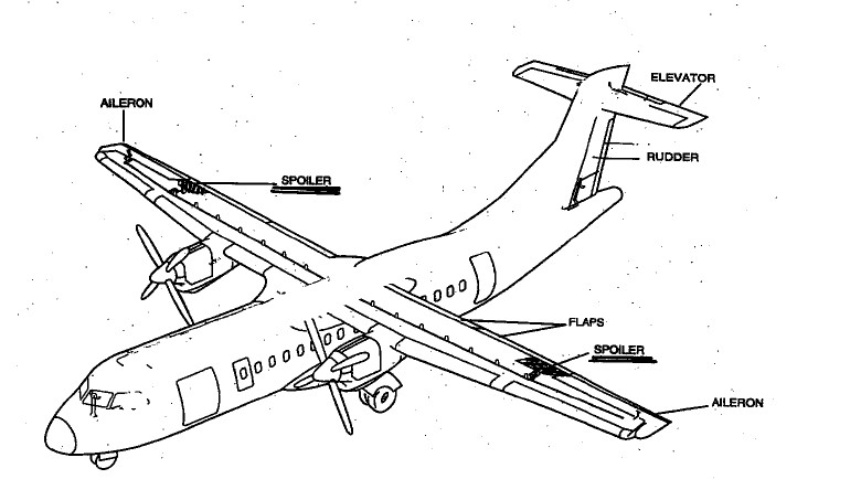
The manual describes the communication required during the conduct of the last chance inspections:
F. PRE-TAKE OFF (LAST CHANCE) INSPECTIONS – REPORTING
This inspection will be accomplished using a “Call and Response” method when trained crew members complete individual elements of the inspection.
When the Pilot-in-Command calls for the inspection at the runway threshold, crew members are to communicate clearly the result of the inspection. ie: "My wing is clean" or "I have snow on my wing".
Under no circumstances are vague or ambiguous terms to be used.Footnote 266
Training
The GIOP manual also describes the training in place to meet the requirements of the regulations,Footnote 267 and relevant standards.Footnote 268
West Wind provided its pilots with an online initial and recurrent training program that covers the hazards of icing and the policies regarding the clean aircraft concept. The program did not include any specific information about the equipment required to inspect or de-ice an aircraft the size of an ATR 42, nor was this information required by regulation.
1.18.3.5 Equipment at Fond-du-Lac Airport
The ATR 42 aircraft’s main critical surfaces, the wing and horizontal stabilizer, are 3.76 m and 7.75 m above the ground, respectively.
At CZFD, there was no equipment available that would enable someone to visually inspect the top portion of an ATR 42’s critical surfaces, given their height, nor to reach them to apply de-icing fluid. The only equipment available were 2 ladders, 1 approximately 3.44 m and the other 1.83 m (Figure 37). The 3.44 m ladder had a maximum standing height of 2.77 m.
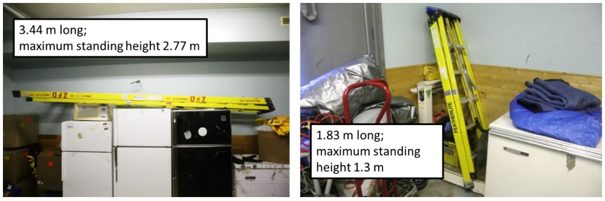
West Wind’s de-icing spray equipment at CZFD consisted of a hand-held spray system with a small-capacity heated fluid reservoir and 20 L container of additional type I fluid.Footnote 269 Another air operator also had a small (20 L), heated hand-held spray system in the terminal building that was available to West Wind personnel on request (Figure 38).
Published de-icing standards recommend that the fluid quantity required to de-ice an aircraft is 1 L/m2 of aircraft surface. In the case of an ATR 42 aircraft, more than 66 L would be required.Footnote 270
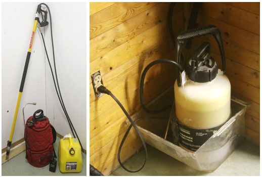
1.18.3.6 Actual inspection at Fond-du-Lac Airport
Once the passengers had boarded the aircraft for departure, the FO walked around the aircraft to conduct a visual external inspection, as required in ground icing conditions.
Although it was dark and there was limited lighting on the apron, the FO observed contamination on the nose of the aircraft and some residual ice on the leading edges of the wings, engine intakes, and on the vertical stabilizer. The FO also noticed ice hanging from power lines near the terminal, and on nearby structures and vegetation. The external inspection ended with the FO visually examining the left wing from the top of the airstair door on the left side of the rear cabin before returning to the cockpit. The FO did not request or make use of the available, albeit inadequate, ladders.
Although surface contamination was identified during the inspection, the FO did not request de-icing equipment or attempt to use the equipment himself. The FO informed the captain about the ice that he noticed on the power lines, and that this ice was on the aircraft as well. The captain responded in a manner that suggested he was not concerned, and, shortly afterward, requested the before-start checklist.
Once on the threshold, immediately before takeoff, the crew completed the last portion of the before-takeoff checklist, which included the “last-chance inspection” as part of the flight control check. The captain stated that he had the representative surface (the left spoiler) in sight. The FO responded that had the right spoiler in sight, but just barely.
1.18.3.7 Similar occurrences
The problem of aircraft departing with frost, ice, or snow adhering to their critical surfaces is not a new one, nor is the problem isolated to Canada’s remote northern airports. The investigation gathered a list of similar occurrences in Canada (Appendix J) and worldwide (Appendix K) in which contaminants on critical surfaces of aircraft during takeoff was a factor.
1.18.4 TSB Watchlist
The TSB Watchlist identifies key safety issues that need to be addressed to make Canada’s transportation system even safer.
Safety management and regulatory surveillance are Watchlist 2020 issues.
As this occurrence demonstrates, some companies consider safety to be adequate as long as they are in compliance with regulatory requirements, but regulations alone cannot predict all risks unique to a particular operation. That is why the TSB has repeatedly emphasized the advantages of SMS, an internationally recognized framework that allows companies to manage risk effectively and make operations safer.
ACTIONS REQUIRED
Regulatory surveillance will remain on the Watchlist for the air transportation sector until TC demonstrates, through surveillance activity assessments, that the new surveillance procedures are identifying and rectifying non-compliances, and that TC is ensuring that a company returns to compliance in a timely fashion and is able to manage the safety of its operations.
ACTIONS REQUIRED
Safety management will remain on the Watchlist for the air transportation sector until:
- TC implements regulations requiring all commercial operators to have formal safety management processes; and
- Transportation operators that do have an SMS demonstrate to TC that it is working—that hazards are being identified and effective risk-mitigation measures are being implemented.
1.19 Useful or effective investigation techniques
1.19.1 TSB pilot survey
1.19.1.1 Objective
Early in this investigation, it became clear that more information was needed to determine whether the underlying factors identified in this occurrence were present elsewhere in the Canadian commercial aviation industry.
To assess the risks involved with winter operations at remote northern airports, and specifically the risk posed by aircraft taking off with frost, ice, or snow adhering to critical surfaces, the TSB decided to reach out to pilots who were directly exposed to operations in remote airports throughout Canada through an online data collection method, to quickly and efficiently reach a large number of these pilots. This took the form of an online questionnaire for commercial pilots employed by air operators operating at remote northern airports under Part VI or Part VII of the CARs. The online platform permitted anonymous collection of responses and stored the responses on servers located in Canada.
1.19.1.2 Participants
The TSB emailed bilingual pilot invitations to 83 Canadian commercial air operators that, on 31 May 2018, operated under subparts 604, 702, 703, 704, and 705 of the CARs.Footnote 271 The selected operators were those likely to have flights taking off from the airports shown in Figure 39. Large national airline operators that operate primarily from airports in southern Canada were deliberately excluded.
Invitations were also sent to several pilot unions representing pilots employed by the selected operators, and an aviation industry association of air operators.
All organizations that received the invitation had access to the questionnaire and could choose whether to forward the invitation to their pilots. Questionnaire participation was both voluntary and anonymous; the questionnaire did not request location information or operator identities.
The selected air operators that provided staffing information employed 2768 pilots. Air operators that did not provide pilot numbers are estimated to employ an additional 500 pilots. It is not known how many pilots received invitations forwarded by their operator or union. Additionally, because the invitation and hyperlink to the questionnaire web page were widely distributed, and redistributable, it is possible and likely that additional pilots outside the intended sampling frame had access to the questionnaire.
1.19.1.3 Questionnaire
The questionnaire (Appendix L) contained 24 items and was available online from 23 July to 31 August 2018.
Most questions were phrased as statements, and respondents were asked to rate their experiences on a 5-point Likert scale (Never, Rarely, Sometimes, Usually, or Always; or Strongly disagree, Disagree, Neither agree nor disagree, Agree, or Strongly Agree). A “Does not apply” option was also available.
Statements and other questions explored the following issues:
- Access to ground equipment to inspect aircraft for contamination, de-icing, and anti-icing at remote airports
- Situations in which a flight crew may decide to divert to an alternate airport
- A crew’s ability to have their aircraft de-iced and anti-iced effectively at remote airports
- Whether the respondent’s employer had a company ground icing program
- Pilots’ self-assessed knowledge of the effects of contaminated critical surfaces
- Whether, in the past 5 years, respondents had witnessed other pilots taking off with contaminated critical surfaces
The remaining questions collected information about the pilots and their industry experience:
- Operations category
- Primary aircraft
- Type of pilot licence
- Total flight time
- Total PIC flight time
- Number of years employed as a pilot
- Number of winter seasons in which they have flown to remote airports
- Number of years with current employer
- Primary role with current operator
- Crew position on aircraft they fly most frequently
- Total flight time on aircraft they fly most frequently
- PIC time on aircraft they fly most frequently
1.19.1.4 Responses
The ability to exit the questionnaire and continue progress at a later time was disabled because this option required storage of identifying “cookies,” and some respondents could be using a shared computer to respond to the questionnaire. Consequently, upon returning to the questionnaire page to complete it, respondents were forced to start again. Likely for that reason, many respondents entered duplicate responses: once in an incomplete response, and again in a completed response. To avoid including duplicate responses, only completed responses were used in the analysis.
The questionnaire welcome page was opened 1022 times: 872 times in English and 150 times in French. The welcome page explained the objectives and terms of the questionnaire, and concluded with an agreement button. Of the 1022 visitors, 110 opened the welcome page, but did not continue past the agreement button, and 912 continued by clicking the agreement button.
Not every visitor completed the questionnaire; there were 257 incomplete responses: 228 in English and 29 in French.
Thus, there were 655 complete responses: 551 in English and 104 in French.
1.19.1.5 Key takeaways
Descriptive information about the questions, and the statistics collected from the 655 complete responses, are summarized in Appendix M; however, the key takeaways are detailed in the following table (Table 6).
| Question | Never | Rarely | Sometimes | Usually | Always | Does not apply | Yes | No |
|---|---|---|---|---|---|---|---|---|
| When I am at a remote airport, I have access to ground equipment that enables effective inspection of all of the aircraft’s critical surfaces for contamination. | 26 | 177 | 174 | 178 | 96 | 4 | n/a | n/a |
| When I am at a remote airport, I have access to ground equipment that enables adequate de‑icing of the aircraft’s critical surfaces before takeoff. | 41 | 191 | 177 | 165 | 77 | 4 | n/a | n/a |
| When I am at a remote airport, I have access to ground equipment that enables adequate anti-icing of the aircraft’s critical surfaces before takeoff. | 207 | 206 | 98 | 83 | 45 | 16 | n/a | n/a |
| I am able to have my aircraft de-iced effectively at remote airports. | 37 | 216 | 152 | 180 | 65 | 5 | n/a | n/a |
| I am able to have my aircraft anti-iced effectively at remote airports. | 231 | 213 | 89 | 68 | 29 | 25 | n/a | n/a |
| In the past 5 years, I have seen pilots take off with contaminated critical surfaces. | n/a | n/a | n/a | n/a | n/a | n/a | 483 | 172 |
1.19.1.6 Recommendations issued following the survey
1.19.1.6.1 Access to adequate equipment
The responses received to several questions showed that operations at these remote airports were routinely affected by the unavailability and inadequacy of equipment to inspect, de-ice, or anti-ice aircraft.
Many survey respondents answered that they rarely have access to adequate inspection and de-icing equipment. The unavailability of adequate equipment is a significant underlying factor that prevents pilots from being able to conduct a proper pre-flight inspection for contaminants and from de-icing a contaminated aircraft. Only 37% of respondents reported that they can have their aircraft de-iced effectively at remote airports.
Most survey respondents answered that they rarely have access to adequate anti‑icing equipment. Only 15% of respondents reported that they can have their aircraft anti-iced effectively at remote northern airports. Where anti-icing is not available, flights operating in active ground icing conditions can experience type I fluid failureFootnote 272 because of the short amount of time that type I fluids are able to absorb frozen precipitation.
As demonstrated by this occurrence, when adequate inspection, de-icing, and anti-icing equipment or services are not available at remote airports, this may influence a flight crew’s decision to depart and ultimately result in aircraft being operated with contaminated surfaces. Similar occurrences investigated by the TSB and other agencies over the past 36 years (Appendices J and K) indicate that departures with contaminated surfaces still occur, occasionally with catastrophic consequences. Canada is substantially exposed to the risk of such accidents, given its large and diverse fleet of aircraft operating at remote northern airports where icing conditions are present.
The combined probability and severity of this safety deficiency poses a high risk to aviation safety. The risk likely varies from airport to airport, depending somewhat on the frequency of operations. Identifying high-risk locations for immediate mitigation can quickly reduce the likelihood of aircraft taking off with frost, ice, or snow adhering to any critical surface at those locations.
TC, air operators, and airport authorities have the capacity to identify high‑risk locations, analyze them for hazards and risks, and take mitigating action.
Therefore, in December 2018, the Board issued TSB Recommendation A18-02, which called for Transport Canada to collaborate with air operators and airport authorities to take action to ensure that the proper equipment is available to reduce the likelihood of aircraft taking off with contaminated critical surfaces. See section 4.1.1.1 TSB Recommendation A18-02 on access to adequate equipment for further details.
1.19.1.6.2 Compliance with the clean aircraft concept
The most notable information received from the survey showed that, in the past 5 years, 74% of pilots have seen aircraft take off with contaminated surfaces, in contravention of regulations and the clean aircraft concept. This majority indicates that the issue is systemic, rather than isolated to a small number of operators or a select few locations.
There are many defences in place to ensure the clean aircraft concept is followed, such as regulations, company operating manuals, and SOPs. However, all of these defences rely singularly on flight crew compliance. As seen in this occurrence, when a single-point compliance adaptation is made, aircraft may depart with contaminated surfaces, despite several adequate administrative defences in place.
To mitigate this hazard, TC and air operators must take urgent action to ensure better compliance.
The regulator and other organizations can audit equipment, policies, training, and operations. Air operators could take similar steps or make procedural changes such as incorporating questions in before-start and before-takeoff checklists, with a requirement for a clean aircraft or a mitigation response from the PIC.
Accidents related to contaminated aircraft will continue to occur until the industry and the regulator approach the issue as systemic and take action to eliminate underlying factors that can negatively affect pilot compliance.
Therefore, in December 2018, the Board issued TSB Recommendation A18-03, which called for Transport Canada and air operators to take action to increase compliance with CAR 602.11(2) and reduce the likelihood of aircraft taking off with contaminated critical surfaces. See section 4.1.1.2 TSB Recommendation A18-03 on compliance with the clean aircraft concept for further details.
2.0 Analysis
This accident involved an aircraft that departed with contamination on its critical surfaces, which resulted in a loss of control and collision with terrain that ultimately led to 1 person being fatally injured.
This analysis will focus on those factors that caused or contributed to the accident, including:
- How ice accumulated on the aircraft
- Why the crew were not aware of the extent of the ice
- Why the ice that was known was not removed before departure
- Which factors influenced the decision to depart
- Why the flight crew lost control of the aircraft during the initial climb
- How and why the airframe suffered significant damage during the impact
- Why the occupants received the severity of injuries that they did
- Additionally, this section will analyze several other risks that were not found to be a factor in this occurrence but could have adverse consequences in future occurrences. These risks include issues related to guidance material, survivability, organizational safety, and regulatory oversight.
2.1 Weather and icing
2.1.1 Flight planning
To prepare for the day’s flights, the flight crew, along with the dispatcher, reviewed the latest aerodrome routine meteorological reports (METARs) and the forecast weather, including the aerodrome forecasts (TAFs) and the graphic area forecasts (GFAs).
The GFAs forecast moderate icing in the area of Fond-du-Lac, in clouds, between 2000 and 8000 feet. The forecast also predicted localized moderate icing from the surface to 2000 feet while in the presence of freezing drizzle. However, the GFA did not predict any icing outside of clouds or precipitation from conditions such as freezing fog.
Similarly, the TAFs for Stony Rapids Airport (CYSF), the closest reporting station to Fond-du-Lac Airport (CZFD), forecast conditions throughout the day that included visibilities as low as 2 statute miles (SM) in light snow and occasional mist, but did not forecast any type of icing such as freezing rain, freezing drizzle, or freezing fog.
Weather conditions recorded at CYSF earlier on the occurrence day included icing (ice detected on the probe) without any form of precipitation and without visibilities below 2 SM. Icing was also recorded shortly before the occurrence, with the presence of only light snow.
Weather forecasting guidance is provided to weather specialists in Canada in the Manual of Standards and Procedures for Aviation Forecasts. The guidance in this manual, and in similar U.S. and international manuals, does not allow for the forecasting of icing in TAFs unless there is also rain (freezing rain), drizzle (freezing drizzle), or fog (freezing fog). Because fog is only reportable when the visibility is less than ⅝ SM, there is no provision for the reporting of icing conditions when the source of the icing is mist, in visibilities between ⅝ SM and 6 SM.
The phenomenon of ground ice accumulation in the absence of precipitation or fog, and the conditions that can cause it, are relatively complex and may not be widely understood.
Finding as to risk
If weather forecasting guidance does not allow for the forecasting of icing that can occur in the absence of precipitation or fog, there is an increased risk that pilots will not have advance warning of foreseeable ground icing conditions.
Although the TAFs that the crew and dispatcher reviewed did not contain any forecast icing, the GFAs did contain expected localized ground icing as a result of freezing drizzle in the area of several of the intended stops of West Wind Aviation L.P. (West Wind) flight 282 (WEW282). Although freezing drizzle was not observed by the crew while the aircraft was on the ground at CZFD, the crew of WEW282 and the dispatcher were aware, at the time of planning, of the possibility.
Finding as to causes and contributing factors
Although both the flight crew and the dispatcher were aware of the forecast ground icing, the decision was made to continue with the day’s planned route to several remote airports that had insufficient de-icing facilities.
The acceptance of this plan indicates that the dispatcher and flight crew assessed that the forecast of icing conditions was not sufficient to warrant cancelling any of the planned stopovers.
2.1.2 Icing on approach
Following departure from Saskatoon/John G. Diefenbaker International Airport (CYXE), the occurrence aircraft’s flight to Prince Albert (Glass Field) Airport (CYPA) was uneventful and clear of any icing conditions.
After WEW282 departed CYPA for CZFD, the climb and cruise portions of the flight were also uneventful. While inbound to CZFD, the flight crew obtained a weather update from air traffic control for CYSF that indicated light snow and a ceiling at 2300 feet.
Flight crews flying from CYPA to CZFD normally receive updates for the weather at CYSF, which is 42 nautical miles (NM) to the east of CZFD, because there are no weather observations available for CZFD. In this instance, the weather conditions at CZFD were generally similar to those reported at CYSF but they can vary significantly.
During the aircraft’s descent into CZFD, the flight crew were communicating with 2 flights (TW280 and WEW660) going ahead of them into CZFD, and these flights did not report any icing conditions. About 15 minutes before landing and before going into cloud, the WEW282 flight crew heard flight TW280 reporting that the ground was in sight 6 miles from the airport. This suggested to the flight crew that the weather conditions were not an issue.
Having flights ahead of WEW282 going into CZFD indirectly reinforced the flight crew’s plan to continue with the scheduled flight to CZFD. There is a tendency to continue with the original plan unless there is a sufficiently salient cue not to do so. This is consistent with plan continuation bias (discussed in section 2.2.4.3 Continuation bias).
On the descent to CZFD, while descending through approximately 7600 feet above sea level (ASL), WEW282 encountered light to moderate icing conditions, which persisted until the aircraft descended through the cloud base at 2100 feet ASL. In response to this icing encounter, the crew of WEW282 activated the aircraft anti-icing and de-icing systems.
Finding as to causes and contributing factors
Although the aircraft’s ice-protection systems were activated on the approach to CZFD, the aircraft’s de-icing boots were not designed to shed all of the ice that can accumulate, and the anti-icing systems did not prevent ice accumulation on unprotected surfaces. As a result, some residual ice began to accumulate on the aircraft.
Shortly after ice began to accumulate, the flight crew was alerted by an ICING (ice detected) light, followed by a DEG PERF (degraded performance) light. The combination and timing of these 2 lights indicate that the degraded performance was due to the ice accumulation.
The crew did not discuss the severity of the icing conditions or the option of diverting to another airport. This absence of discussion suggests that each pilot, in isolation, assessed that the icing conditions were not severe enough to warrant diverting from CZFD to a location where conditions were more favourable.
After the aircraft exited the in-flight icing conditions, the de-icing boots cycled twice more before being turned off.
Finding as to causes and contributing factors
Although the flight crew were aware of the ice, there were no handling anomalies noted on the approach. Consequently, the crew likely did not assess that the residual ice was severe enough to have a significant effect on aircraft performance. Subsequently, without any further discussion about the icing, the crew continued the approach and landed at CZFD.
The investigation determined that, despite some further ice removal during the approach, shortly before the aircraft landed at CZFD, drag had increased by 28% and the lift performance had degraded by 10%, compared with a clean aircraft. This increase in drag and decrease in lift performance indicate that the aircraft had significant residual ice adhering to its structure upon arrival.
2.1.3 Icing on the ground
West Wind flight crews that flew into CZFD were generally aware that adequate ground inspection and de-icing equipment for the ATR 42 were unavailable.
The occurrence flight crew were aware that some residual ice remained on the aircraft following the approach and landing at CZFD. The crew were also aware that adequate de-icing equipment was not available at CZFD. The aircraft remained on the ground at CZFD for approximately 48 minutesin active icing conditions.
2.1.3.1 Weather conditions on the ground in Fond-du-Lac Airport
The weather conditions at the time at CZFD included an overcast ceiling at approximately 1000 to 1500 feet above ground level (AGL) and light westerly winds; however, no observable precipitation was reported. The estimated air temperature was below freezing, at about −10°C, varying by 1 to 2 °C around the time of the occurrence. The estimated dew point ranged within 0 to 2 °C of the air temperature. The visibility was uncertain; however, patchy areas of visibility between 3 to 6 SM were forecast to exist at the time. Also, freezing drizzle was being reported at the Fort Smith Airport (CYSM), Northwest Territories, located 151 nautical miles to the west of CZFD in the hours before the occurrence. Freezing drizzle was not observed when WEW282 was on the ground at CZFD.
The small difference between the air temperature and dew point indicates that the water vapour in the air was very close to the saturation limit (90 to 100% relative humidity).
Since the exact local air temperature and dew point at CZFD are not known, the most likely combinations were analyzed to determine the probability of active ground icing conditions. Table 7 provides the calculated frost point temperatures for an assumed air temperature of −10 °C with possible dew points ranging from −10 to −12 °C:
| Air temperature(°C) | Relative humidity | Dew point(°C) | Frost point(°C) |
|---|---|---|---|
| −10 | 100% | −10 | −9 |
| −10 | 92% | −11 | −10 |
| −10 | 85% | −12 | −11 |
In the first row, the air temperature is below the frost point; therefore, active frost is occurring. Clear ice due to mist is also expected as the air and dew point temperatures are the same (100% relative humidity). In the second row, the air and frost point temperatures are equal, so, again, active frost is occurring. Mist may not be present because the air temperature is above the dew point (92% relative humidity).
In the final row, the air temperature is above both the frost and dew points. However, in this case, as well as the others, a colder aircraft surface could locally chill the air below the −10 °C ambient temperature such that frost or mist could form near the surface. In this case, cooling of only 1 °C could cause active frost conditions or clear ice due to mist.
The prevailing ambient conditions at CZFD consisted of nearly saturated water vapour at a sub-zero temperature almost coincident with the dew point and frost point. These conditions indicate that there was probably active frost while the aircraft was on the ground at CZFD, and that clear ice due to mist was highly likely. Both cause ground icing without visible precipitation.
There were significant ice accretions on the structures and vegetation around CZFD before the occurrence. These were a result of the active ground icing conditions that prevailed before the occurrence, including frost and supercooled mist. These conditions continued even after the occurrence, as evidenced by the frozen contamination that formed on the wreckage shortly following the crash.
The weather data and ice observations before and after the occurrence indicated that ground icing was active and persistent at CZFD for an extended period of time.
2.1.3.2 Ground ice formation without falling precipitation
When any portion of an aircraft surface has a local temperature that is colder than the air temperature, the air in contact with the surface will cool by conduction and convection (Table 8).
| Water state | Process | Result |
|---|---|---|
| Water vapour (gas) | Condenses on above-zero surface | Dew |
| Water vapour (gas) | Condenses on sub-zero surface | Frost |
| Dew (liquid) | Freezes when surface cools below zero | Ice |
| Dew (liquid) | Runs down to sub-zero surface and freezes | Ice |
| Ice, frost | Melts when surface warms above zero | Water, shed ice |
| Ice, frost | Sublimates while sub-zero | Water vapour (negligible) |
| Supercooled water droplets (liquid) | Freezes rapidly on contact with sub-zero surface | Ice |
If the air is near water vapour saturation, very little cooling is required before water begins to condense from the air. If the aircraft surface is below freezing, the condensation will be in the form of frost on the aircraft skin.
If the aircraft surface is above freezing, the condensation will be in the form of liquid water drops (dew). As these dew drops run down lower on the aircraft, they may reach surfaces that are below freezing, causing the drops to freeze to ice at that location.
Even if the water drops do not immediately encounter a surface below freezing and remain as liquid dew drops on the aircraft skin, if the aircraft surfaces continue to cool (such as around an engine nacelle after the engine has been shut down), the dew drops can eventually freeze to ice once the local surface temperature drops below freezing. Liquid water can also freeze to ice during taxi or takeoff.
If supercooled mist droplets have formed in the air, they will rapidly freeze on contact with a cold aircraft surface as clear ice. Clear ice can be very difficult to see because it is smooth and appears to be the same colour and finish as the aircraft paint beneath it.
Such saturated conditions at freezing temperaturesFootnote 273 are active ground icing conditions (“active frost”). Although the time for the frost/ice to appear and the rate of growth of frost/ice may vary, the threat is the same: the aircraft surfaces can accumulate frozen contaminants if not protected by anti-icing fluid.
More so than with visible precipitation, ground icing from frost or clear ice requires monitoring of weather data, such as temperature and humidity, to determine whether active ground icing conditions are present.
2.1.3.3 Aircraft temperature
During the flight to CZFD, the aircraft was in air below −10 °C for about 1 hour 40 minutes, of which more than an hour was in air between −35 and −38 °C. Although the actual surface temperature distribution of the aircraft when it landed at CZFD is unknown, much of it would have been significantly colder than the prevailing frost point. The fuel temperature was also likely below the ambient temperature.
2.1.3.4 Ground ice accretion
Once the aircraft was on the ground at CZFD, the moist air in contact with these cold-soaked surfaces would have cooled below the frost and dew points. Frost likely began forming on the aircraft shortly after it landed at CZFD. The frost deposition rate would have varied over the aircraft, being greater on surfaces that were coldest or already contaminated as a result of in-flight ice accretion.Footnote 274 Research sponsored by Transport Canada (TC) has shown that frost normally forms in such conditions.Footnote 275 The occurrence aircraft had no de-icing or anti-icing fluid applied and was exposed for about 48 minutes.
If mist or freezing drizzle occurred at the CZFD apron area at any time while the aircraft was on the ground, the supercooled droplets would have frozen instantly on contact with the aircraft. Although these surfaces would have begun to warm toward the ambient air temperature during the time on the ground, any ice or frost already formed would not have melted as long as they remained below 0 °C.
The aircraft almost certainly accreted frost on the coldest and/or ice-contaminated surfaces shortly after it arrived at CZFD and throughout the time on the ground. Clear ice may also have formed from supercooled mist droplets that froze on contact with sub-zero surfaces. If clear ice had formed, it would have been difficult for the crew to detect its presence during the time on the ground at CZFD.
2.1.3.5 Interaction with residual ice
The aircraft accumulated ice that could not be shed in flight before it landed at CZFD. Several processes could have changed both the shape and distribution of the residual in-flight ice on the airframe. These would have yielded different aerodynamic effects during the takeoff from CZFD than those encountered during the descent and landing.
In general, ice will sublimate into water vapour over time. However, if the water vapour in the air is already near the saturation limit, such as it was at CZFD, the sublimation rate is very slow. Therefore, in this occurrence, a negligible amount of the residual ice would have sublimated during the time on the ground.
Some residual in-flight ice can shed from portions of the airframe by melting, ground vibration, airframe flexing, and other such processes. When this occurs, it can result in irregular ridges at ice edges, which would have a significant aerodynamic effect.
In this occurrence, any ice-contaminated surfaces of the aircraft that warmed above freezing during the time on the ground would have caused the associated ice to begin to melt. This meltwater may have run off onto other sub-zero aircraft surfaces and/or air where it could have re-frozen. One possible cause of the melting may have been exposure to engine exhaust. The right engine was running in “hotel mode” while on the ground. With the influence of light winds and nearby structures, the exhaust plume may have affected only 1 side of the aircraft, causing ice asymmetry on the airframe. In addition, exhaust constituents may have altered the saturation level of the water vapour in the air.
The residual in-flight ice accretions could have interacted with the active ground icing conditions to produce varied ice shapes and distribution over the airframe. Existing ice would have acted as a strong nucleation site for new frost or clear ice formation. Any meltwater may have run through frosted areas before re-freezing, creating ice ridges. Meltwater could also have frozen during taxi or takeoff.
The shape and distribution of the residual in-flight ice accretions may have changed while on the ground, from melting, re-freezing, shedding, and/or growth of frost or ice. Asymmetry of ice on the airframe was possible, particularly from the exhaust plume of the right engine running in “hotel mode.”
Throughout this analysis, no conclusions were drawn about the visible thickness or extent of ice/frost contamination on the aircraft, either residual ice from the flight or icing while on the ground. Any amount of contamination adhering to the critical aircraft surfaces can severely disrupt its aerodynamics.
Either the residual in-flight ice accretions or the ground icing accretions are alone sufficient to account for the loss of control after takeoff. However, in this case, it is likely that both occurred. Several accidents have demonstrated that even a thin layer of frost contamination is sufficient to cause loss of control immediately after takeoff.
Finding as to causes and contributing factors
Weather conditions on the ground were conducive to ice or frost formation, and this, combined with the nucleation sites provided by the residual mixed ice on the aircraft, resulted in the formation of additional ice or frost on the aircraft’s critical surfaces.
Because of the additional ice accreted while the aircraft was on the ground, the shape and distribution of the ice contamination on the aircraft at takeoff was likely significantly different from the residual ice at landing and, as a result, produced very different aerodynamic effects.
2.2 Inspection and de-icing
2.2.1 Equipment
The equipment available for inspecting and de-icing West Wind aircraft at CZFD consisted of 2 ladders, the tallest of which had a maximum standing height of 2.77 m; a hand-held spray system with a small-capacity heated fluid reservoir; and a 20 L container of type I de-icing fluid. There was an additional small, heated hand-held spray system belonging to another operator that was available for use, containing another 20 L.
The ATR 42’s main wing is 3.76 m above ground, and its horizontal stabilizer is 7.75 m above ground. These critical surfaces have a combined surface area of more than 66 m2. The recommended fluid quantity to de-ice an aircraft is 1 L/ m2. In the case of an ATR 42, this would require more than 66 L.
Due to the height of the aircraft’s critical surfaces and the maximum standing height of the available ladders, neither of the 2 ladders was high enough to permit an adequate inspection or to de-ice the ATR 42 wing or horizontal stabilizer. The available de-icing systems, even if combined, had insufficient fluid capacity to de-ice an ATR 42.
The flight crew did not attempt to de-ice the aircraft, or request to have ground staff de-ice it. However, had they done so, the equipment available would not have been adequate, and the attempt to de-ice would likely have been unsuccessful.
2.2.2 Inspection before departure
The WEW282 flight crew were aware of the residual ice on the aircraft before landing at CZFD. Following landing and disembarkation, the FO left the cockpit to inspect the aircraft.
As mentioned, neither of the available ladders was high enough to permit an inspection of the aircraft, and the FO did not attempt to use either ladder to conduct the inspection. Rather, the inspection consisted of the FO walking around the aircraft on the dimly lit apron, without a flashlight, and looking at the left wing from the top of the stairs at the left rear entry door (L2).
When ATR 42 flight crews inspect the upper surfaces of the aircraft from L2, the whole right wing, the top of the horizontal stabilizer and some other parts of the aircraft cannot be seen; depending on the lighting conditions, even the parts of the aircraft that can be seen may not be clearly visible. Likely as a result of this difficulty, no ice or contaminants were noted during the upper surface inspection.
Finding as to causes and contributing factors
Because the available inspection equipment was inadequate, the FO’s ice inspection consisted only of walking around the aircraft on the dimly lit apron, without a flashlight, and looking at the left wing from the top of the stairs at the left rear entry door (L2). As a result, the full extent of the residual ice and ongoing accretion was unknown to the flight crew.
During the walkaround, however, the FO did note contamination on the nose of the aircraft, and some residual ice on leading edges of the wings, engine intakes, and the vertical stabilizer. The FO also noted that ice was sticking to nearby power lines and vegetation.
While it could not be determined whether the crew were aware that the atmospheric conditions during the ground stop were conducive to icing (in the absence of precipitation or fog), it was determined that they were aware of some of the resulting ice accumulation. Because the pilots did not observe any precipitation while on the ground, this may have biased their assessment as to the extent of the new contamination on the aircraft.
When the FO returned to the cockpit, he briefly discussed the ice he noticed with the captain, and mentioned that there was more ice than he originally thought and that what was visible on the ground was also sticking to the aircraft. The captain responded in a way that suggested he was not concerned and did not inspect the aircraft himself.
2.2.3 Clean aircraft concept
The clean aircraft concept is a framework of regulations, standards, policies, and procedures that prohibits pilots from attempting to conduct a takeoff with frost, snow, or ice adhering to any of the aircraft’s critical surfaces. While this concept or defence is sound in principle, it allows for a single-point of failure at the level of flight crew decision making. The basis for the flight crew’s decisions in this occurrence will be discussed further in section 2.2.4 Flight crew decision making.
Although the clean aircraft concept relies ultimately on the single-point defence of flight crew compliance, numerous organizational defences are also in place to help flight crews to make decisions, to recognize and mitigate risks, and to reduce the likelihood of aircraft departing with contamination.
2.2.3.1 Regulations
Canadian Aviation Regulations (CARs) 602.11(2) states that “No person shall conduct or attempt to conduct a take-off in an aircraft that has frost, ice or snow adhering to any of its critical surfaces.”
This regulation was in force at the time of the occurrence, but it did not prevent the crew from conducting the takeoff with a contaminated aircraft. The regulation itself is clear and explicit; however, its effectiveness depends on pilot compliance and the adequacy of other defences by the air operator.
2.2.3.2 Company guidance
Information, instructions, and guidance regarding icing operations for the ATR 42 can be found in a number of company and aircraft manuals. These include the company operations manual, which includes the Subpart 705 operations manual, and the ATR 42 standard operating procedures (SOPs), which are derived from the ATR 42 Airplane Flight Manual (AFM), Flight Crew Operating Manual (FCOM), and Quick Reference Handbook.
In addition to these, as required by CAR 602.11(4)(b), West Wind has a ground icing operations program (GIOP) in place to address the standards found in the Commercial Air Services Standard 622.11 – Ground Icing Operations. This program is outlined in the company’s GIOP manual.
These manuals all contain similar guidance regarding aircraft inspection when icing conditions are present, procedures for de-icing or anti-icing, and prohibiting takeoff with any frost, ice, or snow adhering to any of the aircraft’s critical surfaces.
The GIOP manual details many of the hazards involved with icing and various sources of ice, snow, or frost, but the manual does not specify any explicit procedure for identifying ground icing conditions, although regulator guidanceFootnote 276 and the GIOP manual itself state that it must. The manual simply states that ground icing conditions exist when frost, ice, or snow is adhering or may adhere to the critical surfaces of an aircraft.
The identification of ground icing conditions is the trigger for when ground icing procedures, such as inspection and de-icing, are required. While some of the weather conditions that present a hazard of ground icing are obvious, such as freezing precipitation, others are not as obvious, such as freezing mist that is not in the forecast, as was present in this occurrence.
Finding as to risk
If GIOPs do not clearly define a procedure to identify ground icing conditions, flight crews may not initiate inspection and de-icing procedures, increasing the risk of aircraft taking off with contaminated surfaces.
Although the manuals did not define the ground icing hazard that was present at the time of the accident, the crew were aware of icing conditions and inspected the aircraft to a limited extent given the available equipment.
The manuals are clear concerning what to do if contamination is detected during these inspections; however, the manuals do not address what equipment might be required to inspect and/or de-ice an ATR 42, or what to do if this equipment is unavailable, as was the case at CZFD. Specifically, the manuals require that the upper surface of the horizontal stabilizer be inspected; however, this upper surface is 7.75 m above ground, making inspection from the ground impossible.
Finding as to risk
If guidance material that requires the inspection of aircraft surfaces that are not visible from the ground does not detail a procedure to conduct this inspection, there is a risk that the inspection will not be completed, and surface contamination will go undetected.
The company manuals also required that any identified deficiencies regarding equipment or procedures be reported through the company’s safety management system (SMS). A review of the company’s SMS database noted that, although some SMS reports were related to de-icing procedures, the hazards associated with some de-icing equipment, and the cancellation of flights because ground de-icing equipment was unserviceable at airports typically served by de-icing equipment, there were no SMS reports concerning the inadequacy or unavailability of de-icing equipment at airports such as CZFD, or regarding departures performed with ice contamination. The absence of reports suggests that the inadequate equipment condition was considered normal, and the practice of operating without it had become normalized (see section 2.2.4.2 Adaptations and normalization).
Finding as to risk
If staff who are aware of deficiencies in de-icing procedures, or the availability of equipment, do not report these hazards through the company’s SMS, there is a risk that the hazards will not be documented, assessed, and mitigated.
2.2.3.3 Training
West Wind provided initial and recurrent training programs regarding the hazard of icing and had policies regarding the clean aircraft concept. The training provided details on the various sources of aircraft icing, including icing that can occur in the absence of precipitation.
Although the training was thorough, it did not include any specific information on what equipment would be required to inspect and de-ice an ATR 42, or the availability of required equipment at the company’s routine destinations.
2.2.4 Flight crew decision making
Although there were many administrative defences in place to ensure that the clean aircraft concept was understood and followed, the flight crew of WEW282 decided to depart from CZFD with contamination on the aircraft’s critical surfaces.
This section will analyze the many factors that led to that decision and the biases that led the crew to think that their chosen course of action was safe. It will also analyze why some of the defences in place to assist this decision making were ineffective at preventing a negative outcome.
2.2.4.1 Crew resource management
Crew resource management (CRM) is the most widely accepted aid to flight crew decision making and a main defence against a wide range of threats, errors, and undesired states. It has come to be understood as an umbrella term that includes virtually every facet of safety at a modern air operator.
Crews at West Wind, including the occurrence crew, received regular and recurrent training in the many aspects of CRM.
The foundation of CRM is clear, open, and effective communication among crew members. This communication fosters effective teamwork, enhances shared situational awareness, improves crew decision making, and aids in the prevention, detection, or mitigation of errors. Modern CRM also includes the concept of threat and error management (TEM).
This section will discuss some of the reasons these combined defences were unable to mitigate the hazard or prevent the flight crew from departing with contamination on the aircraft.
2.2.4.1.1 Intra-crew communication
When the FO reported to the captain that the aircraft had ice on it, the captain was working on weight and balance calculations. The discussion between the pilots about the ice lasted only 9 seconds before the captain immediately returned to the calculations.
In response to the FO report that the aircraft was contaminated, the captain acknowledged the message, but the discussion ended there. There was no explicit discussion about the threat posed by the ice, accepting the risk related to the ice, or about de-icing the aircraft or other mitigation.
The FO did not pursue the discussion, suggesting that he did not view the ice as an issue that warranted escalation. Six seconds after the discussion ended, the captain told the FO they had 7 more passengers than anticipated and called for the before-start check. Three minutes later, the FO mentioned the ice again, although this mention was again brief and did not seem to involve significant concern; the captain’s response similarly did not show concern.
The FO’s communication that there was ice on the aircraft was received and understood by the captain. However, the statements were only that ice was present and did not include any information on the extent of the contamination or suggestions concerning potential consequences or mitigations.
The FO made the statements while the captain’s attention was on other pre-takeoff tasks, and the captain immediately went back to those tasks. The fact that neither pilot continued the discussion suggests that they both accepted the presence of the ice and thought that there was no need to de-ice or delay the flight.
2.2.4.1.2 Trans-cockpit authority gradient
The decisional hierarchy or trans-cockpit authority gradient between the 2 pilots was relatively flat. Both pilots were experienced in northern operations and had previously been paired together.
There was no discussion between the captain and FO on the threat posed by icing on the aircraft. Each pilot carried out a quick assessment in isolation. This negated the opportunity for the crew to discuss the potential extent of the contamination, and options to address the threat posed by icing. The flat authority gradient may have inadvertently created a barrier to effective communication. Both pilots may have made assumptions concerning the other pilot’s situational awareness and decision making.
Finding as to risk
When a trans-cockpit authority gradient is relatively flat, communications may be less effective and pilots may make erroneous assumptions concerning the other pilot’s situational awareness and decision-making, increasing the risk that hazards to flight will not be identified and addressed by the crew.
2.2.4.1.3 Threat and error management
The key principles of TEM are anticipation of, recognition of, and recovery from threats and errors. It advocates carefully analyzing potential hazards and taking appropriate steps to avoid, trap, or mitigate threats and errors before they lead to an undesired aircraft state. Flight crews may trap an error by identifying and correcting it, exacerbate an error by making a subsequent error, or have no effect on the error as a result of not detecting it or ignoring it.Footnote 277
TEM briefings can be a very helpful tool to help crews develop a shared understanding of the threats and errors perceived by either crew member and to develop a common plan to mitigate the risk. TEM briefing checklists are normally developed to help steer crew identification and discussion into specific areas that have previously been identified as potentially hazardous.
West Wind had voluntarily introduced TEM briefings in its SOPs before the accident, although it was not required to do so by regulation, because the company recognized the safety benefits of crews proactively discussing strategies for potential threats. The TEM checklist on WEW282 contained a bullet regarding “cold wx ops” (cold weather operations), but nothing specific to aircraft icing. However, the checklist is not intended to be exhaustive.
Before the aircraft departed from CZFD on the occurrence flight, the captain’s take-off briefing addressed the threat posed by the “black hole” effect. This threat was regularly present during night departures at remote airports, and the crew were aware of how to manage it.
Although the crew were aware of icing on the aircraft, this topic was not raised as a threat during this briefing, likely because there was only 1 option for mitigation—to not depart—and the decision to depart had already been made.
In terms of analyzing decision making, a decision to take deliberate action that would deviate from a known rule or standard procedure is known as an adaptation. Because of the deliberate nature of these decisions, TEM briefings can possibly be ineffective in addressing adaptations that have been made in a single-crew operation or collective decisions in a multi-crew situation, because the decision to adapt has already been made.
More specifically, if flight crews have already collectively decided to deviate from a standard rule, especially one as explicit as the clean aircraft concept, and it has become common practice to do so, it is unlikely that this intentional deviation (or adaptation) would be raised for discussion during the briefing because the mitigation method intended to trap this error would have already been discarded. For example, if a flight crew decided to depart overweight, it would be unlikely that they would openly discuss options to mitigate this error, when the only clearly safe option—to not depart—had already been decided against.
Finding as to risk
Although TEM briefings are helpful, if they are relied upon to mitigate threats or errors that are systemic adaptations, there is a risk that the hazards will continue, especially if the threat itself is non-compliance with the mitigation method.
Put more simply, if choosing to break a rule is the identified error, then there is little point in discussing how to avoid doing that.
While this TEM method might not catch a systemic adaptation shortly before the action is taken, it theoretically could be effective if it is applied from a broader perspective. If the operator had recognized ahead of time that decisions to depart might be influenced by cognitive biases, it may have taken steps to manage this threat. However, there was no indication that this overarching threat was identified at the time of the occurrence.
2.2.4.2 Adaptations and normalization
Regulators, manufacturers, and operators develop rules, policies, and procedures that are aimed at setting safe limits for operations. However, often influenced by pressure to be more productive or cognitive biases, people occasionally make decisions to not stay within those limits. When it is repeated over time, this variance results in adaptations of the procedures themselves and in deviation from prescribed limits, leading to unsafe practices.Footnote 278
Normally, these procedural adaptations do not have visible and immediate adverse consequences. The threats to safety that they pose are not obvious, because the adaptation of procedures or regulations does not immediately lead to an accident. Moreover, when flights are carried out successfully over an increasingly long period of time, the practice becomes normalized because the pilots recognize the frequent advantages of the adaptations but rarely see the potentially catastrophic consequences.
With regard to operations in remote locations such as CZFD, the equipment available to inspect and de-ice the aircraft was often inadequate, and this was known to flight crews. This meant that, once on the ground, if ice was detected, the choice was either to depart with some contamination or to cancel the flight and cause a prolonged delay. Because the only available de-icing equipment was incapable of de-icing an ATR 42 aircraft, the delay created by a decision to de-ice would not be in terms of minutes, it could be in terms of days.
One of these options was clearly extremely negative with regard to productivity, while the other had no immediate adverse consequence. When faced with this pressure, in order to remain productive, flight crews flying out of these remote locations begin to make adaptations.
Finding as to risk
If adequate de-icing equipment is unavailable, especially at locations with routine operations, there is a risk that, if ice is detected, the perceived pressure from causing extensive delays may lead flight crews to make adaptations to the clean aircraft concept and depart with contamination on the aircraft’s critical surfaces.
Without regular supervision, education, or enforcement of prescribed limits, some people will tend to keep adapting the procedures and taking shortcuts until they reach safety limits, leading to an unsafe situation and potentially an accident.
From 2014 until the occurrence flight, West Wind conducted 188 ATR 42 stopovers at CZFD, 101 of which were during the months of October, November, and December. The 188 flights had an average stopover time of 25 minutes. This quick turnaround time indicates that these aircraft were likely never de-iced, and that no takeoffs from CZFD were ever delayed or cancelled because of icing conditions. In fact, investigation data indicate that some takeoffs likely proceeded with ice on the aircraft.
Although the 188 flights to CZFD represent a low percentage of West Wind’s total ATR 42 operations, they are considered representative of West Wind’s operations into remote locations.
As previously mentioned, during this time period, no SMS reports filed by flight crews identified the inadequate equipment at CZFD, or its effect on decisions to depart with contamination on the aircraft, further suggesting that the practice had become a normal part of operations.
Finding as to causes and contributing factors
Departing from remote airports, such as CZFD, with some amount of surface contamination on the aircraft’s critical surfaces, had become common practice, in part due to the inadequacy of de-icing equipment or services at these locations. The past success of these adaptations resulted in the unsafe practice becoming normalized and this normalization influenced the flight crew’s decision to depart.
2.2.4.3 Continuation bias
Plan continuation can be described as the tendency for an individual to continue with an original plan of action in the face of cues that together, in hindsight, warranted changing the plan. In cases of plan continuation, people’s understanding of the situation gradually diverges from the situation as it actually turned out to be. Plan continuation almost always results from
- early and sustained cues that suggest the plan is safe and that are compelling and unambiguous; and
- later cues that suggest the situation is changing but are much weaker, difficult to process, ambiguous, or contradictory.Footnote 279
Once a plan is made and committed to, it becomes increasingly difficult for stimuli or conditions in the environment to be recognized as necessitating a change to the plan. Often, as workload increases, the stimuli or conditions will appear obvious to people external to the situation; however, it can be very difficult for a pilot caught up in the plan to recognize the saliency of the cues and the need to alter the plan.Footnote 280
In this occurrence, even before landing at CZFD, the crew had developed a plan that involved a prompt departure and did not involve de-icing the aircraft. There were several early and sustained cues on the inbound flight that suggested to the crew that this plan was safe, including:
- the fact that 2 aircraft had proceeded safely to CZFD before the occurrence flight;
- the compelling knowledge that they had done this safely before;
- the normal aircraft handling despite the degraded performance alerts; and
- the absence of significant concern or discussion raised by either pilot about the current conditions.
Later cues that came to the crew suggesting a change in plan may be required, were slightly weaker, uncertain, and even contradictory. When the FO returned to the cockpit following the walkaround, the new information he provided regarding the ice was neither detailed nor compelling. At around the same time, another aircraft departed safely, which served to contradict any potential perception that the icing was significant. Finally, when the crew completed their last check for ice before departure, although the captain reported that the spoiler, the representative surface he was required to inspect for ice, was clear, the FO’s view was limited, and the FO told the captain that he could barely see the spoiler on his side. As a result, the flight crew’s assessment of the severity of the ice on this final check was based on incomplete information.
Finding as to causes and contributing factors
Although the flight crew were aware of icing on the aircraft’s critical surfaces, they decided that the occurrence departure could be accomplished safely. Their decision to continue with the original plan to depart was influenced by continuation bias, as they perceived the initial and sustained cues that supported their plan as more compelling than the later cues that suggested another course of action.
2.2.5 Recommendations following pilot survey
During July and August 2018, the TSB sought information from pilots operating into and out of remote airports in Canada. To gather this information, an online survey was conducted. The survey had 655 responses and provided useful insight into compliance with the clean aircraft concept and the adequacy of de-icing and anti-icing facilities at remote locations.
The key takeaways from the results can be summarized with the following statements. In terms of a percentage of respondents:
- 74% indicated that they had witnessed pilots take off with contaminated critical surfaces in the past 5 years.
- 39% indicated that they are never or rarely able to have their aircraft de-iced.
- 35% indicated that they never or rarely have access to ground equipment that enables adequate de-icing of their aircraft at remote airports.
- 31% indicated that they never or rarely have access to ground equipment that enables effective inspection of the aircraft’s critical surfaces.
In December 2018, once the data from the survey were analyzed, and connections were established between the data and the underlying factors involved in this occurrence, the Board issued 2 recommendations to address the 2 identified areas of greatest risk: the availability of adequate de-icing and anti-icing equipment, and compliance with the clean aircraft concept.
TC’s latest responses (September 2020) and updates (November 2020) to these recommendations indicated that TC had created a stakeholder working group, improved training and produced material to raise awareness of the hazards of aircraft taking off with contaminated critical surfaces. The COVID-19 pandemic has presented challenges to the industry and to TC. These challenges have delayed the development of concrete actions to ensure proper de-icing and anti-icing equipment is available to reduce the likelihood of aircraft taking off with contaminated critical surfaces, and prevented most of TC’s planned targeted inspections aimed at increasing compliance with CAR 602.11(2).
While these actions, once seen through to completion, may have the potential to substantially mitigate the risk associated with the safety deficiency, at the time of report publication, these actions had yet to be implemented.
Finding as to risk
Until actions are implemented to address the availability of anti-icing and de-icing equipment (TSB Recommendation A18-02) and compliance (TSB Recommendation A18-03), there remains a persistent risk that pilots will not comply with the clean aircraft concept and will continue to take off with contaminated aircraft.
2.3 Takeoff and loss of control
2.3.1 Performance calculations
When the crew prepared take-off performance calculations for departure, they used the METAR for CYSF that they had received on approach to CZFD. This METAR indicated a temperature of −10 °C, a few clouds at 1400 feet AGL, and a broken ceiling at 2300 feet AGL.
Guidance in the AFM states that atmospheric icing exists when the temperature is below 10 °C and visible moisture in any form, such as clouds, is present. It does not specify whether the aircraft has to be in these referenced clouds, or whether the existence of the clouds alone is sufficient. For example, if clouds were forecast at 200 feet, it might be clear that atmospheric icing conditions existed on departure, but if the clouds were few and at 2000 feet, it may not be as clear whether icing conditions prevailed, or not.
Guidance in the FCOM states that speed limitations must be complied with as soon as the icing conditions are met; however, this relies on the AFM explanation of atmospheric icing and does not clarify whether speed limitations are required for clouds that will not be entered during the takeoff.
When aircraft are certified, certification standards require the aircraft to be able to encounter icing while on the take-off path, which continues from the ground up to 1500 feet. Aircraft manufacturers must establish icing speeds that will be used to maintain obstacle clearance requirements following an engine failure on takeoff in icing conditions.
Because these speeds are calculated for the take-off path, it would therefore follow that, if icing conditions exist below 1500 feet AGL, icing speeds should be used for the takeoff. This information, however, is not supplied to pilots in any of the guidance provided by the manufacturer, company, or regulator, outside of interpreting the regulations or certification standards themselves.
The use of appropriate take-off speeds is important to ensure that the aircraft can clear obstacles on takeoff or stop on the remaining runway, should the crew need to abort takeoff. Because icing speeds are always higher than non-icing speeds, their use increases the take-off distance required, or, in cases where the distance is limited, reduces the allowable take-off weight.
Finding as to risk
If the guidance provided to pilots to help them determine when to select take-off icing speeds is not clear and well-defined, flight crews may select a take-off speed or operating weight that will result in the aircraft being unable to meet the minimum performance requirements set by certification standards, thereby increasing the risk of an accident.
Before the occurrence departure, the flight crew perceived that they would not encounter in-flight icing on takeoff, and, as a result, the crew selected non-icing speeds for the takeoff and Level 1 for ice protection. On takeoff, there was likely no further significant in-flight ice accretion because there was no precipitation and because the aircraft never entered the cloud layers that were likely present at approximately 1400 and 2300 feet AGL, as reported at CYSF. Therefore, it could be interpreted that the protection afforded by these icing speeds was not required.
Similarly, the flight crew did not apply performance penalties that may have been required because of the unpaved runway surface, which was possibly also contaminated with snow patches.
Softer runways normally require longer take-off distances and therefore penalties when calculating take-off performance. There was no specific guidance supplied by the aircraft manufacturer for operations on sealed-gravel runways, and the regulator’s guidance stated that frozen unpaved surfaces had qualities similar to those of paved surfaces. With knowledge of this guidance, the crew determined that a performance penalty was not required for the departure.
Additionally, the most recent runway surface condition report, issued 11 hours before the occurrence departure, recorded that 40% of the runway was covered in snow patches. However, this condition no longer existed on the next report, 13 hours later, so it could not be determined whether the condition existed at the time of departure. Runway surface contamination greater than 25% requires an additional penalty, but no penalty was calculated by the flight crew.
Finding as to risk
If flight crews do not apply the take-off performance calculation penalties required for contaminated or unpaved runways, they might operate at take-off weights or on runway lengths that do not meet, their aircraft’s capabilities, increasing the risk of a runway excursion or accident.
2.3.2 Aircraft contamination
The aircraft accumulated ice on approach, and, although most of it was shed by the de-icing system, some remained on landing. This residual ice acted as nucleation sites for the accretion of further ice during the aircraft’s 48-minute stop on the ground.
During the investigation, the physical evidence of ice contamination on the critical surfaces of the aircraft was difficult to distinguish from that accumulated following the accident. Therefore, an aerodynamic analysis was conducted to identify the presence and effect of ice contamination.
Finding as to causes and contributing factors
As a result of the ice that remained on the aircraft following the approach and the additional ice that had accreted during the ground stop, the aircraft’s drag was increased by 58% and its lift was decreased by 25% during the takeoff.
2.3.3 Loss of control in the roll axis
Finding as to causes and contributing factors
During the takeoff, despite the degraded performance, the aircraft initially climbed; however, immediately after lift off, the aircraft began to roll to the left without any pilot input. This roll was as a result of asymmetric lift distribution due to uneven ice contamination on the aircraft.
To counteract this roll, the captain added full right aileron and the aircraft began to roll right, although at a reduced rate compared to what he expected to normally occur, given the amount of input.
Finding as to causes and contributing factors
Following the uncommanded roll, the captain reacted as if the aircraft was an uncontaminated ATR 42, with the expectation of normal handling qualities and dynamic response characteristics; however, due to the contamination, the aircraft had diminished roll damping resulting in unexpected handling qualities and dynamic response.
The flight data from the departure were compared with hundreds of other flights, and it was determined that, at this moment, there was a degradation in roll control authority; however, subsequent analysis determined that the degradation was not critical and that the ailerons in fact had sufficient roll control authority to counteract the asymmetric lift.
Four seconds after the initial left roll and attempted recovery, the airplane continued to roll to the right, through level, and entered a more significant right bank, followed 4 seconds later by an even more significant left bank.
Finding as to causes and contributing factors
Although the investigation determined that the ailerons had sufficient roll control authority to counteract the asymmetric lift, due to the unexpected handling qualities and dynamic response, the roll disturbance developed into an oscillation with growing magnitude and control in the roll axis was lost.
On the 3rd oscillation, when the roll angle reached its peak, the stall warning sounded and the nose was lowered. Although the aircraft was close to the stall at this point, the stick pusher had not yet activated, and therefore this nose-down pitch movement was likely a result of a control input made by the captain.
During the 4th oscillation, after reaching a peak of 142 feet above ground, the aircraft began to descend. The captain raised the nose, but the bank angle also began to increase, now back towards the left and into the 5th oscillation. Due to the increasing bank, the aircraft continued to descend, the stall warning sounded again, and the aircraft collided with the ground shortly after the peak of the 5th oscillation.
Finding as to causes and contributing factors
This loss of control in the roll axis, which corresponds with the known risks associated with taking off with ice contamination, ultimately led to the aircraft colliding with terrain.
2.4 Collision with terrain
Finding as to causes and contributing factors
The aircraft collided with the ground in relatively level pitch, with a bank angle of 30° left. As a result of the sudden vertical deceleration upon contact with the ground, the aircraft suffered significant damage, which varied in severity at different locations on the aircraft because of the impact angle and the variability in structural design.
2.4.1 Estimation of impact forces
The aircraft struck the ground in an area of down-sloping terrain. Once the fuselage struck the ground, the aircraft began to rotate or yaw to the left. By the time the aircraft came to rest, it was oriented nearly 90° in relation to the path of travel during the impact sequence. As a result of this rotation, although the peak longitudinal (forward) acceleration force was estimated to be 4g in the direction of travel, the aircraft and its occupants received significant lateral loads nearing 4g as well. The exact initial impact force in a vertical direction was not determined, but it was not large enough to cause the passenger seats to deform to the left when the aircraft collided with the ground when banked 30° to the left.
2.4.2 Crashworthiness
Crashworthiness is generally defined as the ability of an aircraft and its internal systems and components to protect the occupants from injury in the event of a crash. Aircraft design regulations require that aircraft “structure must be designed to give each occupant every reasonable chance of escaping serious injury in a minor crash landing.”Footnote 281
During the U.S. Federal Aviation Administration (FAA) vertical drop test of an ATR 42 simulating a severe, but survivable, crash impact, the aircraft fuselage sustained major structural damage and would not in fact have given each occupant every reasonable chance of escaping serious injury. The main landing gear housing structure, which served as the lower portion of the centre fuselage section, did not progressively crush in the same way as the remaining fuselage. This resulted in the centre fuselage section, above the main landing gear housing structure, sustaining major structural damage as the inertial load from the wing crushed the upper portion of the fuselage, resulting in a loss of survivable space for the occupants in the centre section of the passenger cabin.
In this occurrence, the vertical impact velocity of the aircraft was significantly lower than that in the FAA drop test, as evidenced by comparing the amount of deformation of the seats during the FAA drop test with the amount of deformation to the seats in this occurrence; yet, the key structural damage was almost identical to that observed in the FAA’s test. Specifically, the main landing gear housing structure, beneath the passenger cabin, did not exhibit signs of vertical crushing, and the area above it was significantly damaged.
The ATR 42-320 certification basis was set in 1985 to the FAA’s Code of Federal Regulations, Title 14: Aeronautics and Space, Part 25: Airworthiness Standards: Transport Category Airplanes (FAR 25), up to and including amendment 54. Although FAR 25.561 was amended in 1988 to include a requirement that seats and supporting structures must not deform in a manner that could impede rapid evacuation of occupants, this requirement did not apply to the ATR 42-320.
To protect occupants, an aircraft’s structure must absorb impact energy in a way that eliminates or minimizes cabin deformation and reduces the acceleration loads transmitted to the occupants. Although the certification regulations require that seats and their attachments meet requirements for inertial loads transmitted from the occupants, the current certification standard does not specify specific crash landing loads for fuselage structure design or specify that the fuselage structure must be designed for impact energy absorption.
Finding as to causes and contributing factors
Neither current design standards for transport category aircraft, nor those in effect at the time the ATR 42 was certified, specify minimum loads that a fuselage structure must be able to tolerate and remain survivable, or minimum loads for fuselage impact energy absorption. As a result, the ATR 42 was not designed with such crashworthiness parameters in mind.
Instead of being designed for crashworthiness, the lower portion of the centre fuselage section, specifically the main landing gear housing structure, was designed to be rigid in order to transfer loads from the landing gear.
2.4.3 Damage from the impact
In keeping with the modest vertical energy during the impact, apart from the centre fuselage section, the damage to the majority of the fuselage was modest. The upper portions of the forward and aft fuselage sections had maintained their approximately circular shape, indicating that the lower portion of these sections had effectively absorbed the impact energy.
In contrast to this modest damage, however, the centre fuselage section sustained severe structural damage, and its upper portion collapsed.
The structural damage compromised the survivable space, the restraint systems, the evacuation aisle, and power to the emergency lights and communications systems; it limited access to the emergency exits, and delayed and impeded the evacuation. The effects of the damage resulted in the injury and trapping of occupants and the death of 1 passenger.
2.4.3.1 Wing collapse
In this aircraft type, the main landing gear is stowed inside the lower portion of the centre fuselage section, and the landing gear housing structure is built using solid bulkheads joined by a solid keel beam. Following the accident, no sign of appreciable vertical crushing was found in this area, indicating that the structure was too rigid to absorb the impact energy effectively in the vertical direction. This absence of crushing, or energy attenuation, resulted in the full impact force being distributed through the centre fuselage section above the landing gear housing structure.
Mounted directly above the centre fuselage is the aircraft’s wing. The wing carries a significant load, given that the engines are mounted on it and the built-in fuel tanks carrying all of the aircraft’s fuel are contained within it.
Finding as to causes and contributing factors
On impact, the induced acceleration was not attenuated because the landing gear housing did not deform. This unattenuated acceleration resulted in a large inertial load from the wing, causing the wing support structure to fail and the wing to collapse into the cabin.
The crushing of the upper portion of the centre fuselage section by the inertial force from the wing severely compromised the structural integrity of the fuselage as a whole. This crushing reduced the survivable space for occupants in the centre section of the passenger cabin and was a key factor leading to the transverse fracture of the fuselage at the location just forward of the forward wing spar.
Finding as to risk
When the wing collapsed, the integral fuel became uncontained and leaked out, significantly increasing the risk of a post-impact fire at a time when passengers were unable to evacuate.
Finding as to risk
Following the wing collapse, the leaked fuel entered the survivable space, and with the outside temperature of approximately –10 °C, the passengers who were soaked in fuel faced an increased risk of hypothermia.
Finding as to risk
The collapse also resulted in structural and terrain hazards entering the cabin survivable space. These intrusions increased the risk of injuries for those occupants flailing in their seats during the accident sequence, and also to evacuating passengers who had to climb through the cabin, over seats and hazards, to evacuate the aircraft.
2.4.3.2 Floor structure
Differential vertical crushing of the lower portions of the fuselage sections also resulted in fracture and collapse of the floor structure at locations forward and aft of the main landing gear housing structure.
The cabin floor frame of the occurrence aircraft was constructed using transverse beams and seat tracks. There were 2 types of connections between the transverse beam and the seat tracks, depending on whether a single piece of seat track passed over the transverse beam (type I), or if 2 seat tracks made an end-to-end connection at the transverse beam (type II).
The type II joint design is considered weaker than the type I joint design. In keeping with this view, all type II joints of the floor frames of the occurrence aircraft failed, whereas the type I joints did not. The failures were found to be caused by transfer of the longitudinal load from the seat tracks to the joint.
The cabin floor buckled from the rear of the passenger cabin toward the centre of the passenger cabin. This was due to the twisting between the centre and aft fuselage sections and the differential crushing damage to the lower portion of the centre and aft fuselage sections. It is likely that the rigid design of the lower portion of the centre fuselage section contributed to such abnormal floor structure deformation and damage.
3.4.3.3 Flight attendant seat
The laboratory examination of the flight attendant (FA) seat determined that it had undergone unapproved repairs on the honeycomb structure sandwich panel. As a result, there were a significant number of bubbles and unfilled voids at the bonding interface of the sandwich panel, and the strength of the seat-structure assembly was likely far lower than it was in the original design. This was likely the reason the FA’s seat failed and broke into pieces in this occurrence.
The shop that performed the last repair on the structural assembly of the FA seat is no longer in business. Because of this, no further information could be obtained as to why it selected a standard composite repair procedure not applicable to the FA seat.
A review of the inspection and repair procedure for the FA seat in the Component Maintenance Manual (CMM) determined that the inspection and repair procedures for the structure assembly of the FA seat were not clear. While the CMM stated that metal components were not repairable, it was not clear whether a “shaped honeycomb structure sandwich panel” was considered a metal component. Strictly speaking, the honeycomb sandwich panel is not a metal component because of the presence of adhesive bonding layers in its structure. It is normally referred as either “honeycomb sandwich panel” or “composite” in aircraft structural repair.
The ambiguity in inspection and repair procedures for the structure assembly of the FA seat was likely one of the factors contributing to the unapproved repair of the FA seat, as it may have caused confusion for a technician who did the inspection and repair. A post-occurrence examination of an FA seat from another West Wind ATR 42, found signs of similar unapproved repairs, suggesting that the misunderstanding of the CMM with regards to the repairability of the honeycomb panels may be a widespread issue.
2.5 Injuries
All passengers and crew were injured. Many were rendered temporarily unconscious. The captain and 9 passengers were seriouslyFootnote 282 injured, and 1 of these passengers later died as a result of the injuries received.
The sequence of events during the impact and subsequent slide induced injuries from initial vertical forces, injuries from jackknifing and flailing, crushing injuries as a result of the wing and floor structure collapse, more severe flailing injuries due to the reduced survivable space, and injuries from lateral acceleration forces and associated lateral flailing. Due to the amount of passenger displacement and collision with aircraft parts, it was impossible to determine the exact nature or order of injuries for each passenger.
However, an analysis of injuries indicated that head, body, and leg trauma were more common in the middle-forward left section of the aircraft. This is consistent with the degree of crushing in this area, given that the living space in this area was compromised by the wing above collapsing downwards, and the floor below being pushed upward.
The analysis also indicated that back-related trauma was more common in the middle-rear right section of the aircraft. This is consistent with the lateral forces and rotation applied to this side of the aircraft, which resulted in lateral deceleration forces for occupants of seats that had a compromised restraint system.
2.5.1 Serious and fatal passenger injuries
Finding as to causes and contributing factors
The reduced survivable space between the floor above the main landing gear and the collapsed upper fuselage caused crushing injuries, such as major head, body, and leg trauma, to passengers in the middle-forward left section of the aircraft. Of the 3 passengers in this area, 2 experienced serious, life-changing injuries and 1 passenger died.
2.5.2 Other injuries to passengers and flight crew
Although the occurrence impact forces were within human tolerance levels, an analysis of occupant injuries indicated that many of the passengers and the captain received serious velocity-related injuries, such as compression injuries and back fractures.
The initial impact forces (vertical downward deceleration force of approximately 4g) did not exceed the passenger seat design limits of 4.0g lateral, 7.2g vertical (downward), or 9.0g longitudinal (forward). Although most seats were pushed into other seats, some were deformed, and many had displaced seat tracks, the flight crew and passenger seats all performed as designed.
The deformations, displacements, and associated loss of restraint effectiveness were primarily due to the collapse of part of the floor structure, not the failure of the seats. Given that the seat structures were all attached to the floor, any floor deformation could significantly reduce the overall effectiveness of restraints, regardless of seat or belt type.
With seats already vulnerable as a result of the floor deformation, when the aircraft turned to the left, the force applied laterally to the fuselage approached the seats’ side load limit of 4g. This resulted in a deflection of the seats to the right, which likely contributed to the injuries sustained by those in the right-side seats.
Finding as to causes and contributing factors
The collapse of part of the floor structure compromised the restraint systems, limiting the protection afforded to the occupants when they were experiencing vertical, longitudinal, and lateral forces. This resulted in serious velocity-related injuries and impeded their ability to take post-impact survival actions in a timely manner.
2.5.2.1 Adult restraint systems
The passenger seats were the type with locked-out seatbacks, designed to remain upright after flexing following an impact from the rear, and were equipped with typical 2-point lap belts.
When occupants are exposed to impact forces, this can result in several different types of velocity-related injuries, such as flail injuries from uncontrolled arm, leg, and head movements; jackknife injuries from the upper torso folding forward or to the side; and/or submarining injuries, from sliding out from under a lap belt.
When compared with passengers in seats with shoulder harnesses, passengers in seats with 2-point lap belts that do not restrain the torso are at a greater risk of concentrated acceleration forces around the hips and abdomen and at a greater risk of serious injuries from flailing, jackknifing, and submarining.
To mitigate the risk of injury to occupants seated in aircraft seats without torso restraints or head impact protection, such as the occurrence aircraft, it is important that those occupants assume a proper brace position. The seats in the ATR 42 were designed before head-impact protection criteria were required; therefore, the only remaining mitigation for the risk of flailing, jackknifing, or submarining injuries was reliance upon passengers to assume a correct brace position before or during an impact sequence.
There are many factors that affect the probability of a passenger bracing before impact, including the anticipation of a collision, timely instructions from the crew, or an understanding of the need to brace, by reading the safety-features card. Because these factors are often absent, passenger bracing may not be done correctly.
Finding as to causes and contributing factors
Most passengers in this occurrence did not brace before impact. Because their torsos were unrestrained, they received injuries consistent with jackknifing and flailing, such as hitting the seat in front of them.
2.5.3 Infant injury
The occurrence aircraft had no child restraint systems, nor was the operator required to provide these. Similar to what has been documented in other accidents, in this occurrence, a parent was unable to effectively restrain their infant on their lap during the impact sequence. As a result, the infant was projected into the seat in front, receiving projection-related injuries and subsequent crushing injuries from being trapped.
In 2015, the TSB recommended that TC work with industry to develop child-restraint systems for infants and young children and to mandate their use. The regulator responded that it would examine the issue, but at the time of writing this report, there has been no progress toward any action.
Finding as to causes and contributing factors
Given that regulations requiring the use of child-restraint systems have yet to be implemented, the aircraft was not equipped with these devices. As a result, the infant passenger was unrestrained and received flail and crushing injuries.
2.5.4 Flight attendant injury
The FA seat failed on impact; as a result, the FA was projected into the aisle, suffered multiple minor injuries, was incapacitated for the remaining 9 seconds of the impact sequence, and was delayed in responding to the crash.
The FA seat was found to have a significant number of defects in its seat structure as a result of repairs that were not in accordance with the CMM for the seat. The defects in the seat structure were likely the main reason it broke into pieces during the occurrence.
Finding as to causes and contributing factors
As a result of unapproved repairs, the FA seat failed on impact, resulting in injuries that impeded her ability to perform evacuation and survival actions in a timely manner.
2.6 Evacuation
After the FA was able to free herself from the projected FA seat, she attempted to communicate with the flight crew but was unable to because the transverse fracture of the fuselage had disabled the power supply for intra-crew communications. The FA therefore initiated evacuation of the passengers.
The FA attempted to open the rear entry door (L2) to evacuate the aircraft; however, she was unable to do so. The structural damage from impact had resulted in the displacement of internal cabin partitions and caused the handle for the L2 door to become trapped behind the partition, restricting the FA’s and passengers’ access to it. The FA and able-bodied passengers instead had to kick the service door (R2), which was partially blocked by terrain, for several minutes before it finally opened and occupants were able to exit the aircraft.
Similarly, the damage displaced cargo poles that were part of the cargo restraint systems; as a result, cargo spilled loose within the forward cargo hold, blocking the escape route from the cockpit. Because of this blockage, the evacuation of the flight crew was significantly delayed. The FO evacuated through the cockpit hatch, and the captain had to be extracted through the hatch with outside assistance.
As a result of these difficulties, it took approximately 20 minutes for the first 17 passengers remaining in the aircraft to evacuate, while other passengers remained trapped. The last passenger was removed from the wreckage 3 hours after the accident.
The current design standards for transport category aircraft state that equipment, passenger compartment cargo, and any other large masses in the cabin, must be positioned so that, if they break loose, they will be unlikely to prevent the use of any of the escape facilities intended to be used following an emergency landing. However, this standard became applicable after the ATR 42 was type-certified and, as a result, did not apply to the occurrence aircraft.
Finding as to risk
As shown in this occurrence, on aircraft certified to older standards, there is a risk that displacement of cargo restraint systems and cabin partitions that are positioned adjacent to an evacuation route could impede the evacuation route for survivors.
2.7 Regulatory oversight
2.7.1 Surveillance planning
All transportation companies have a responsibility to manage the safety risks within their operations. A move toward safety management systems (SMS) has great potential to enhance safety by encouraging operators to put in place a systemic approach to manage safety proactively.
Given that companies will inevitably have varying degrees of ability or commitment to manage safety effectively, the regulator needs to ensure compliance with existing regulations. To do this, the regulator needs to be able to provide oversight in a manner that encourages the proactive identification and mitigation of risks, while intervening when necessary to ensure, at a minimum, regulatory compliance.
Guidance from the International Civil Aviation Organization (ICAO)Footnote 283 states that all significant aspects of an operator’s procedures and practices should be evaluated at least once every 12 months. Before 2012, TC’s surveillance policies and procedures met this criterion, as companies in all sectors were required to undergo an inspection at least every 12 months and an audit every 3 years.
However, in 2012, TC changed its surveillance policy and increased the surveillance interval for program validation inspections (PVIs) to a maximum of 3 years and for assessments to 5 years. The selection of a surveillance interval for a particular operator would be determined based on a company’s risk-profile score, calculated using the National Aviation Safety Information Management System (NASIMS). The change to this policy was based on the premise that companies assessed as low risk and/or low complexity would be more effective at managing safety than others, using tools such as SMS, quality assurance programs, and other defences.
Between 2010 and 2013, the regulator had identified several concerns with non-conformance within the quality assurance and safety oversight components of West Wind’s SMS. Despite these identified issues, in the months following the 2013 PVI, the regulator adjusted the company’s surveillance schedule from planned annual PVIs to a 4-year interval in accordance with newly released internal guidance. This action was based on the regulator’s computed risk score for West Wind at the time (2D, low risk high impact). As a result of this adjustment, direct regulatory oversight of the company was significantly reduced.
Between the 2013 PVI and the 2016 assessment, TC’s surveillance of West Wind was limited to administrative review of documents, approved check pilot monitors, and cabin safety in-flight checks. During that 3-year period, the company was not subject to any additional surveillance activities, such as assessments, PVIs, or process inspections (PIs).
Based on the issues identified by the regulator from 2010 to 2013, it is unclear how TC determined that it had adequate assurances to place West Wind on a 4-year planned surveillance interval. As seen in this occurrence, this decision reduced the oversight of a company that did not consistently demonstrate the ability of its SMS to effectively manage safety. This became readily apparent during the 2016 assessment, which resulted in major and moderate findings of non-compliance.
From 2012 to 2019, one of the primary tools TC used to determine a company’s surveillance interval (i.e., 1 to 5 years) was the applicable risk-profile score in NASIMS. The risk-profile score obtained through NASIMS was one of the key considerations during TC’s annual surveillance planning.
However, as seen in this occurrence and identified in the 2012 Spring Report of the Auditor General of Canada and TSB Aviation Investigation Report A13H0001, NASIMS was not regularly updated, either because there were no surveillance activities or because database updates were not completed in a timely manner.
Many of the responses to the West Wind risk-profile questions in NASIMS had not been updated since 2012, and some that had been updated were not done so accurately. For example, a major finding of non-compliance identified in the 2013 PVI was not recorded as such. As a result of the responses not being updated regularly, and the inaccuracy of some of the responses that were updated, West Wind’s risk-profile score did not accurately reflect its actual risk profile.
After West Wind’s initial NASIMS risk-profile score in 2012, the company’s risk-indicator value initially decreased and then remained unchanged for almost 2 years, due to the absence of updates. West Wind’s score dropped again in 2015, reaching a low just before TC’s 2016 assessment. As a result, although there were likely ongoing issues at the company with regard to regulatory compliance, as evidenced by the 8 major and 2 moderate findings during the 2016 assessment, TC’s process for monitoring changes in company risk profiles was inaccurately showing that risk levels decreased from 2013 to the 2016 assessment.
The results of the 2016 assessment, and the resulting spike in West Wind’s NASIMS risk-indicator number, demonstrate that, for the period from 2013 to 2016, TC did not have an accurate understanding of the risks present at the company.
In order for NASIMS, or any other risk-profile system, to be effective, regular and accurate updates to risk-indicator scores are required.
Finding as to risk
If company risk profiles maintained by the regulator are not up to date and accurate, changes in a company’s risk profile may go undetected and surveillance activities might be reduced, allowing unsafe conditions to develop or persist.
2.7.2 Inconsistent application of policies and procedures
2.7.2.1 General
The investigation revealed a number of instances in which TC’s surveillance policies and procedures were inconsistently applied to the oversight of West Wind. This is not the first time that such inconsistencies in TC’s oversight of commercial aviation in Canada have been identified. As detailed in the findings of several TSB investigations, there have been a number of past examples where TC has been slow to either identify or to rectify unsafe conditions at an operator (Appendix H).
2.7.2.2 2016 assessment
After a 3-year period of very little oversight activity, TC initiated an assessment of West Wind in 2016. The 2016 assessment revealed numerous major findings throughout the company’s operations, most of which were related to SMS requirements under CARs Subpart 107.
While the assessment was underway, during both on-site and post-surveillance decision making, TC considered taking certificate action, such as suspension or cancellation of the company’s air operator certificate; however, in September 2016, West Wind voluntarily suspended its Subpart 705 operations, and shortly thereafter suspended its Subpart 703 and 704 operations. TC’s decision making on certificate action was influenced by West Wind’s decision to suspend operations, as well as the company’s acceptance of TC’s findings and West Wind’s willingness to complete short- and long-term corrective action plans (CAPs).
Since the company, which is an SMS enterprise, expressed interest in addressing the identified problems through the CAP process, regional TC personnel understood that national policy obligated them to follow the CAP process with West Wind. In addition, regional TC personnel understood that certificate or enforcement action would be counterproductive, since it seemed to contradict TC’s approach to providing oversight to SMS enterprises.
As a result, regional TC personnel selected strategies for dealing with West Wind that were not consistent with national-level surveillance policies and procedures at the time. These decisions allowed unsafe conditions to persist at West Wind.
Examples include the following:
- TC terminated the assessment without assessing SMS component 1 – Safety Management Plan and made no provision to ensure that it was assessed later. As a result, TC did not have assurances that the company’s safety management plan would be effective at ensuring the company’s timely return to a state of compliance.
- TC assessed SMS component 3 – Safety Oversight as compliant, despite the fact that some elements were assessed as only partially implemented.
- TC assessed SMS component 4 – Quality Assurance as non-compliant. TC had previously identified this component as being non-compliant on multiple occasions since 2010, and, although actions were taken individually, nothing was done to address the systemic nature of the recurring issue.
- The assessment report identified legacy issues, lack of communication, and complacency; however, it did not provide any supporting evidence or analysis for these issues.
- Despite multiple major findings of non-compliance, TC did not issue any detection notices to West Wind. As a result, critical information needed to support certificate action was not captured.
The results of the 2016 assessment met several of the criteria considered mandatory for invoking the Oversight Advisory Board (OAB). In particular, it involved a high-profile operator with multiple major findings, and an operator that would be placed under enhanced monitoring (EM).
Despite this, the OAB was not consulted about West Wind following the 2016 assessment, and, as a result, the regional TC office did not receive national-level guidance on the appropriate course of action. Without consulting the OAB, regional TC personnel, who were unaware of newly published surveillance procedures, placed West Wind under EM following the 2016 assessment, despite multiple major findings and new surveillance procedures directing them to escalate the situation to national oversight.
2.7.2.3 On-site follow-up of West Wind’s corrective action plans
TC policies and procedures (i.e., Staff Instruction [SI] SUR-001) state that CAP implementation should be followed up within 90 days of CAP acceptance. Although TC initially advised West Wind on 12 December 2016 that it would conduct on-site verification within 90 days, this verification did not happen as planned. Some of the 2016 assessment CAPs were verified by TC in April 2017; however, the majority of CAPs were still open at the time of the occurrence, almost 1 year after the CAP acceptance dates.
This means that CAP verification was approximately 9 months overdue at the time of the accident. Therefore, TC’s management of West Wind’s CAPs following the 2016 assessment was not in accordance with its policies. SI SUR-001 recommends a risk assessment be conducted if CAP verification is going to take longer than 90 days. TC did not follow this recommended procedure; therefore, regional TC management did not have a clear understanding of the risk of allowing West Wind to continue operating under EM.
SI SUR-001 states that, if CAP implementation will take longer than 12 months, the matter must be referred to both regional management and the National Civil Aviation Management Executive (NCAMX). However, it was not in this case, and the decisions related to the oversight of West Wind remained primarily at the regional level. As a result, the regional TC office did not have the benefit of national-level decision-making support to ensure that actions taken following the 2016 assessment were consistent with national-level policies.
By not adhering to CAP verification policies and procedures following the 2016 assessment, TC was unable to ensure that the unsafe conditions that were identified during the assessment were being rectified.
2.7.2.4 Conduct of the enhanced monitoring following 2016 assessment
The goal of placing a company under EM is to return the company to a state of regulatory compliance and to confirm that the necessary systems are in place to ensure ongoing compliance. To help ensure the effective use of EM, and a standardized approach, TC has published national-level EM policies and procedures. These are found primarily in SI SUR-002; however, EM is referenced in a number of other TC documents.
The investigation discovered several instances in which TC deviated from these policies and procedures, adopting an ad hoc approach to the EM of West Wind. For example, a critical component to the success of EM is the production of a focused EM surveillance plan (as required by SI SUR-002). This plan should clearly define EM team roles and responsibilities, conditions for EM termination, and timelines for the verification period and terminating PVI. There is no record of an EM surveillance plan for West Wind being prepared or approved by the regulator.
The absence of a plan resulted in there being no clear definition of the scope, team roles and responsibilities, EM activities, timeframe, or the conditions that needed to be met to terminate EM. Instead, the regulator selected a prolonged open-ended period of EM with no clear timeline or conditions for exit. This absence of direction and focus likely contributed to unsafe conditions persisting for an extended period—almost 12 months—before the accident.
Finding as to risk
If the regulator does not create and follow a plan for EM, as required by its internal procedures, there is a risk that the EM will be ineffective in helping return companies to regulatory compliance.
2.7.2.5 Conclusion
Finding: Other
TC’s inconsistent application of its own policies and procedures for the 2016 assessment and post-assessment CAP verifications, as well as the ad hoc approach to EM, resulted in ineffective oversight of an operator that had a history of system-level (i.e., SMS) and systemic (e.g., operational control) non-compliance issues.
Rather than taking immediate action to address the identified non-compliance issues, TC instead selected a prolonged, open-ended period of EM, which proved ineffective at returning West Wind to a state of compliance.
By contrast, after the accident, TC conducted a reactive PI, which identified several significant areas of non-compliance. In addition, the OAB was convened to review the results of the post-occurrence PI and to recommend action, which resulted in the issuance of an immediate notice of suspension to West Wind. This timely OAB engagement was effective, but it was not consistent with the actions taken following the 2016 assessment.
Finding as to risk
If the application of TC’s surveillance policies and procedures is inconsistent, there is a risk that resulting oversight will not ensure that operators are able to effectively manage the safety of their operations.
2.7.3 Policies and procedures for Transport Canada inspectors
TC inspectors rely on a variety of national-level policy documents and staff instructions to help them make decisions and conduct surveillance activities. To ensure the correct and consistent application of TC’s surveillance procedures, relevant information must be easily accessible, clear, and concise. In addition, inspectors must be made aware, in a timely manner, of newly issued or amended publications.
The investigation noted a number of variances and potential for different interpretations in TC’s policy documents and instructions. In some instances, inspectors were unaware of newly issued or amended documents and instructions that are critical to their surveillance duties.
Some documents overlap with others, yet do not reference the other document. For example, SI SUR-001 and SI SUR-029 both contain instructions for enforcement action; however, neither references the other. Topics such as EM and CAP procedures span multiple documents.
The guidance for EM provided to regional personnel was largely in text format, and did not include clear decision-making or planning tools such as flow charts, timeline templates, or specific checklists to follow to ensure that EM was conducted in accordance with national policy.
There is no process to ensure that TC inspectors review recently issued or amended publications. Instead, the onus is placed on the inspector to review these documents. As a result, TC management does not have a process in place to ensure that inspectors are familiar with the current policies and procedures in effect.
The combination of these factors increases the complexity of regional inspectors’ day-to-day responsibilities and could contribute to the inconsistent application of regulatory oversight. Instead of a single reference document outlining each aspect of their job, inspectors must often review multiple, overlapping documents that are subject to change at any time.
This occurrence highlights the risk posed by this situation, as regional inspectors were unaware of critical guidance (i.e., IPB 2016-04) that directed the most appropriate course of action for West Wind following the 2016 assessment. Instead, the regional inspectors acted on their understanding at the time when deciding how to proceed with West Wind.
Finding as to risk
If TC’s oversight guidance material for its inspectors is distributed among several different documents, and TC does not ensure that amendments to this guidance are received and understood, inspectors may not follow the latest guidance, and as a result, will not achieve the intended safety objectives.
2.8 West Wind safety management system
2.8.1 West Wind safety management and safety culture
While transportation companies have a responsibility to manage safety risks in their operations, compliance with regulations can provide only a baseline level of safety.
When implemented properly, SMS enables companies to manage risk effectively and make operations safer. However, for SMS to be effective, it must be supported by a positive safety culture—one that starts at the top of the company with clearly established philosophies, policies, and procedures. There must be alignment between these and practices (4 Ps). Practices give an indication of the effectiveness of the procedures, policies, and the philosophies. They can also help identify gaps.
This occurrence involved a CARs Subpart 705 operator with an SMS assessed and accepted by TC; however, some of its SMS-related activities did not achieve the intended level of safety. These activities, which are a measure of West Wind’s safety culture, reflected a misalignment between the 4 Ps, as these actions were not being conducted in accordance with company procedures, formal policies (including regulations), or the company’s stated higher-level goal of safe operations.
For example, in 2014, the company had developed informal policies related to operations on the narrow runways at CZFD and Wollaston Lake Airport (CZWL). However, at the time of the accident—3 years later—these policies still had not been incorporated into the company’s operations manual. Although not directly related to this accident, this slow action shows a tolerance for practices that are outside of established policy or procedure.
Similarly, in 2014, the day before commencing operations at CZFD, the company closed off a risk assessment regarding ATR 42 operations into CZFD and CZWL, although it was incomplete and was unable to identify several operational threats, such as ground icing, that flight crews would be expected to manage when flying into these locations. As a result, the company did not have an accurate understanding of the risks associated with operating out of CZFD in the winter months without adequate de-icing equipment.
In the years before the accident, West Wind’s safety culture had progressively become less effective, likely due, in part, to inconsistent leadership. Since 2010, there had been considerable management personnel turnover at the company, particularly in the positions of Director of Flight Operations (DFO) and Subpart 705 Chief Pilot. In December 2016, to address issues raised in TC’s 2016 assessment, the DFO absorbed the roles and responsibilities of both the Director of Regulatory Standards and Compliance and the Subpart 705 Chief Pilot. Although this was intended to be a temporary fix, it remained that way for almost 1 year, ending 1 month before the accident.
The increased workload of this arrangement was substantial and likely reduced the DFO’s capacity to adequately provide operational control and maintain compliance with all regulations. This resulted in a misalignment of the 4 Ps within the organization, the general acceptance of unsafe practices, and an inability to detect and rectify systemic non-compliance issues—factors that all indicate a degraded safety culture.
From a broader perspective, the TSB investigation determined that this acceptance of unsafe practices extended beyond West Wind. The TSB’s questionnaire revealed that other pilots operating at remote locations also take off with contaminated critical aircraft surfaces, even though this practice is contrary to established regulations and represents a serious risk to transportation safety.
Finding as to risk
If a company’s safety culture tolerates unsafe practices, there is a risk that these practices will continue and become a company norm.
2.8.2 Safety risk management
One of the 4 components of an effective SMS is safety risk management: proactively identifying hazards, assessing risk, implementing risk mitigation strategies, and evaluating their effectiveness. A detailed, systematic risk management process gives companies a better understanding of the challenges to expect in a particular operating environment, resulting in higher levels of safety performance.
Hazard identification is the first step in safety risk management. When embarking on a new operation, there are a number of potential hazard areas to consider. This is particularly important for challenging operations, such as those conducted into remote locations with limited support infrastructure.
In an effort to address this risk, West Wind opened a risk assessment in May 2014 to look into the potential hazards with commencing new operations into CZFD. The assessment was closed on 11 September 2014, the day before commencing ATR 42 operations into CZFD.
Some of the hazards with operating into remote locations are well known, such as a lack of weather reporting services, a lack of flight-following services, and even the absence of de-icing equipment. However, companies assessing the risk of this type of operation should also attempt to identify, in a systematic manner, less obvious hazards. This can be accomplished by reviewing hazard reports, conducting safety surveys, or using knowledge from subject-matter experts who have additional insight on the hazards associated with a particular operation.
In this occurrence, West Wind’s safety risk management process did not identify or explore several hazards associated with operating at CZFD and CZWL. Instead, West Wind identified the hazard as an “ORM [operational risk management] exercise for proposed operations into Fond du Lac and Wollison [sic] Lake with the ATR 42.”
Using this as the identified hazard, the company determined the probability to be unlikely and the severity to be major. This hazard statement was imprecise and did not accurately state the hazards, which would have made it difficult to accurately describe and assess the risk level of the proposed operation.
It is likely that West Wind, as an organization, did not have a thorough understanding of risk management practices and, therefore, did not have the ability to accurately complete the risk management process.
Another important aspect of safety risk management is the consideration of underlying factors that may themselves be hazards, or may influence other identified hazards. In the case of assessing operations into these remote areas, it may have been possible to identify potential internal or external pressure that could influence pilot decision making, resulting in a hazardous outcome; however, the assessment did not identify this pressure.
West Wind’s risk assessment did not take into account these potential influences on pilots, the self-described “can do” pilot subculture, or the lack of support to assist pilot decision making. As a result, West Wind did not have a complete understanding of the hazards that existed in 2014 and persisted until the occurrence.
Once hazards are well defined, organizations must then assess the risk and determine what, if any, risk controls can be implemented to reduce risk to as low as reasonably practicable.
Finding as to risk
If organizations do not adequately identify hazards and analyze risks, potential mitigation methods can be overlooked, increasing the risk of an adverse consequence.
This is what occurred at West Wind during its risk assessment of the operations into CZFD and CZWL. Because the company did not accurately identify the hazards, it was therefore unable to apply adequate risk control measures.
Finding as to causes and contributing factors
When West Wind commenced operations into CZFD in 2014, no effective risk controls were in place to mitigate the potential hazard of ground icing at CZFD.
If the hazards had been properly identified during the 2014 risk assessment, the company could have reinforced existing policies regarding the clean aircraft concept, or provided more specific guidance to aid pilot decision making for ground icing at locations without proper de-icing equipment.
Because of the dynamic nature of commercial aviation, it is important from a safety risk management standpoint that organizations periodically review operational decisions to ensure that previous assumptions remain valid. In the case of the CZFD risk assessment, after it was complete, the company did not revisit it or challenge its original assumptions.
When concerns about the insufficient de-icing equipment were raised by the occurrence captain 1 month after the risk assessment was closed, the company did not take any formal action, such as reopening the risk assessment or amending the SOPs. Instead, it issued a memorandum stating that the risk was acceptable and that the company recognized it would result in approximately 4% of flights being cancelled or delayed. In addition to this memorandum, the company distributed an informal rule by word-of-mouth that these remote locations should be avoided entirely if icing was known to be an issue.
Finding as to risk
If mitigations that are determined following risk assessments are not formalized and properly disseminated, they may not be widely implemented in a sustained fashion, increasing the risk of accidents.
3.0 Findings
3.1 Findings as to causes and contributing factors
These are conditions, acts or safety deficiencies that were found to have caused or contributed to this occurrence.
- When West Wind commenced operations into Fond-du-Lac Airport (CZFD) in 2014, no effective risk controls were in place to mitigate the potential hazard of ground icing at CZFD.
- Although both the flight crew and the dispatcher were aware of the forecast ground icing, the decision was made to continue with the day’s planned route to several remote airports that had insufficient de-icing facilities.
- Although the aircraft’s ice-protection systems were activated on the approach to CZFD, the aircraft’s de-icing boots were not designed to shed all of the ice that can accumulate, and the anti-icing systems did not prevent ice accumulation on unprotected surfaces. As a result, some residual ice began to accumulate on the aircraft.
- Although the flight crew were aware of the ice, there were no handling anomalies noted on the approach. Consequently, the crew likely did not assess that the residual ice was severe enough to have a significant effect on aircraft performance. Subsequently, without any further discussion about the icing, the crew continued the approach and landed at CZFD.
- Weather conditions on the ground were conducive to ice or frost formation, and this, combined with the nucleation sites provided by the residual mixed ice on the aircraft, resulted in the formation of additional ice or frost on the aircraft’s critical surfaces.
- Because the available inspection equipment was inadequate, the first officer’s ice inspection consisted only of walking around the aircraft on a dimly lit apron, without a flashlight, and looking at the left wing from the top of the stairs at the left rear entry door (L2). As a result, the full extent of the residual ice and ongoing accretion was unknown to the flight crew.
- Departing from remote airports, such as CZFD, with some amount of surface contamination on the aircraft’s critical surfaces, had become common practice, in part due to the inadequacy of de-icing equipment or services at these locations. The past success of these adaptations resulted in the unsafe practice becoming normalized and this normalization influenced the flight crew’s decision to depart.
- Although the flight crew were aware of icing on the aircraft’s critical surfaces, they decided that the occurrence departure could be accomplished safely. Their decision to continue with the original plan to depart was influenced by continuation bias, as they perceived the initial and sustained cues that supported their plan as more compelling than the later cues that suggested another course of action.
- As a result of the ice that remained on the aircraft following the approach and the additional ice that had accreted during the ground stop, the aircraft’s drag was increased by 58% and its lift was decreased by 25% during the takeoff.
- During the takeoff, despite the degraded performance, the aircraft initially climbed; however, immediately after lift off, the aircraft began to roll to the left without any pilot input. This roll was as a result of asymmetric lift distribution due to uneven ice contamination on the aircraft.
- Following the uncommanded roll, the captain reacted as if the aircraft was an uncontaminated ATR 42, with the expectation of normal handling qualities and dynamic response characteristics; however, due to the contamination, the aircraft had diminished roll damping resulting in unexpected handling qualities and dynamic response.
- Although the investigation determined the ailerons had sufficient roll control authority to counteract the asymmetric lift, due to the unexpected handling qualities and dynamic response, the roll disturbance developed into an oscillation with growing magnitude and control in the roll axis was lost.
- This loss of control in the roll axis, which corresponds with the known risks associated with taking off with ice contamination, ultimately led to the aircraft colliding with terrain.
- The aircraft collided with the ground in relatively level pitch, with a bank angle of 30° left. As a result of the sudden vertical deceleration upon contact with the ground, the aircraft suffered significant damage, which varied in severity at different locations on the aircraft because of the impact angle and the variability in structural design.
- Neither current design standards for transport category aircraft, nor those in effect at the time the ATR 42 was certified, specify minimum loads that a fuselage structure must be able to tolerate and remain survivable, or minimum loads for fuselage impact energy absorption. As a result, the ATR 42 was not designed with such crashworthiness parameters in mind.
- On impact, the induced acceleration was not attenuated because the landing gear housing did not deform. This unattenuated acceleration resulted in a large inertial load from the wing, causing the wing support structure to fail and the wing to collapse into the cabin.
- The reduced survivable space between the floor above the main landing gear and the collapsed upper fuselage caused crushing injuries, such as major head, body, and leg trauma, to passengers in the middle-forward left section of the aircraft. Of the 3 passengers in this area, 2 experienced serious life-changing injuries, and 1 passenger died.
- The collapse of part of the floor structure compromised the restraint systems, limiting the protection afforded to the occupants when they were experiencing vertical, longitudinal, and lateral forces. This resulted in serious velocity-related injuries and impeded their ability to take post-impact survival actions in a timely manner.
- Most passengers in this occurrence did not brace before impact. Because their torsos were unrestrained, they received injuries consistent with jackknifing and flailing, such as hitting the seat in front of them.
- Given that regulations requiring the use of child-restraint systems have yet to be implemented, the aircraft was not equipped with these devices. As a result, the infant passenger was unrestrained and received flail and crushing injuries.
- As a result of unapproved repairs, the flight attendant seat failed on impact, resulting in injuries that impeded her ability to perform evacuation and survival actions in a timely manner.
3.2 Findings as to risk
These are conditions, unsafe acts or safety deficiencies that were found not to be a factor in this occurrence but could have adverse consequences in future occurrences.
- If weather forecasting guidance does not allow for the forecasting of icing that can occur in the absence of precipitation or fog, there is an increased risk that pilots will not have advance warning of foreseeable ground icing conditions.
- If ground icing operations programs do not clearly define a procedure to identify ground icing conditions, flight crews may not initiate inspection and de-icing procedures, increasing the risk of aircraft taking off with contaminated surfaces.
- If guidance material that requires the inspection of aircraft surfaces that are not visible from the ground does not detail a procedure to conduct this inspection, there is a risk that the inspection will not be completed, and surface contamination will go undetected.
- If staff who are aware of deficiencies in de-icing procedures, or the availability of equipment, do not report these hazards through the company’s safety management system, there is a risk that the hazards will not be documented, assessed, and mitigated.
- When a trans-cockpit authority gradient is relatively flat, communications may be less effective and pilots may make erroneous assumptions concerning the other pilot’s situational awareness and decision-making, increasing the risk that hazards to flight will not be identified and addressed by the crew.
- Although threat and error management briefings are helpful, if they are relied upon to mitigate threats or errors that are systemic adaptations, there is a risk that the hazards will continue, especially if the threat itself is non-compliance with the mitigation method.
- If adequate de-icing equipment is unavailable, especially at locations with routine operations, there is a risk that, if ice is detected, the perceived pressure from causing extensive delays may lead flight crews to make adaptations to the clean aircraft concept and depart with contamination on the aircraft’s critical surfaces.
- Until actions are implemented to address the availability of anti-icing and de-icing equipment (TSB Recommendation A18-02) and compliance (TSB Recommendation A18-03), there remains a persistent risk that pilots will not comply with the clean aircraft concept and will continue to take off with contaminated aircraft.
- If the guidance provided to pilots to help them determine when to select take-off icing speeds is not clear and well-defined, flight crews may select a take-off speed or operating weight that will result in the aircraft being unable to meet the minimum performance requirements set by certification standards, thereby increasing the risk of an accident.
- If flight crews do not apply the take-off performance calculation penalties required for contaminated or unpaved runways, they might operate at take-off weights or on runway lengths that do not meet their aircraft’s capabilities, increasing the risk of a runway excursion or accident.
- When the wing collapsed, the integral fuel became uncontained and leaked out, significantly increasing the risk of a post-impact fire at a time when passengers were unable to evacuate.
- Following the wing collapse, the leaked fuel entered the survivable space, and with the outside temperature of approximately −10 °C, the passengers who were soaked in fuel faced an increased risk of hypothermia.
- The collapse also resulted in structural and terrain hazards entering the cabin survivable space. These intrusions increased the risk of injuries for those occupants flailing in their seats during the accident sequence, and also to evacuating passengers who had to climb through the cabin, over seats and hazards, to evacuate the aircraft.
- As shown in this occurrence, on aircraft certified to older standards, there is a risk that displacement of cargo restraint systems and cabin partitions that are positioned adjacent to an evacuation route could impede the evacuation route for survivors.
- If company risk profiles maintained by the regulator are not up to date and accurate, changes in a company’s risk profile may go undetected and surveillance activities might be reduced, allowing unsafe conditions to develop or persist.
- If the regulator does not create and follow a plan for enhanced monitoring, as required by its internal procedures, there is a risk that the enhanced monitoring will be ineffective in helping return companies to regulatory compliance.
- If the application of Transport Canada’s surveillance policies and procedures is inconsistent, there is a risk that resulting oversight will not ensure that operators are able to effectively manage the safety of their operations.
- If Transport Canada’s oversight guidance material for its inspectors is distributed among several different documents, and Transport Canada does not ensure that amendments to this guidance are received and understood, inspectors may not follow the latest guidance, and as a result, will not achieve the intended safety objectives.
- If a company’s safety culture tolerates unsafe practices, there is a risk that these practices will continue and become a company norm.
- If organizations do not adequately identify hazards and analyze risks, potential mitigation methods can be overlooked, increasing the risk of an adverse consequence.
- If mitigations that are determined following risk assessments are not formalized and properly disseminated, they may not be widely implemented in a sustained fashion, increasing the risk of accidents.
3.3 Other findings
These items could enhance safety, resolve an issue of controversy, or provide a data point for future safety studies.
- Transport Canada’s inconsistent application of its own policies and procedures for the 2016 assessment and post-assessment corrective action plan verifications, as well as the ad hoc approach to enhanced monitoring, resulted in ineffective oversight of an operator that had a history of system-level (i.e., safety management system) and systemic (e.g., operational control) non-compliance issues.
4.0 Safety action
4.1 Safety action taken
4.1.1 Transportation Safety Board of Canada
4.1.1.1 TSB Recommendation A18-02 on access to adequate equipment
The duration of cold weather and icing conditions varies widely across Canada. Many remote northern airports have an icing season of 10 months or more. Icing conditions can be both severe and persistent.
Thousands of flights take off every year from remote northern airports. Some airports serve as hubs, experience higher traffic volumes, and may have better equipment.
The risks of adverse consequences likely vary from airport to airport. Identifying high-risk locations for immediate mitigation has the potential to quickly reduce the likelihood of aircraft taking off with frost, ice, or snow adhering to any critical surface at those locations.
Transport Canada (TC), air operators, and airport authorities have the capacity to identify high‑risk locations, analyze them for hazards and risks, and take mitigating action.
Therefore, in December 2018, the Board recommended that
the Department of Transport collaborate with air operators and airport authorities to identify locations where there is inadequate de-icing and anti-icing equipment and take urgent action to ensure that the proper equipment is available to reduce the likelihood of aircraft taking off with contaminated critical surfaces.
TSB Recommendation A18-02
In its response (September 2020) and update (November 2020) to this recommendation, TC indicated that it had reached out to stakeholders, created working groups, and held discussions to address the safety issues identified in this recommendation. The COVID-19 pandemic has presented many challenges to the industry, which have delayed the development of concrete actions to ensure proper de-icing and anti-icing equipment is available to reduce the likelihood of aircraft taking off with contaminated critical surfaces.
Until steps are taken to ensure proper de-icing and anti-icing equipment is available, the risks associated with the safety deficiency identified in Recommendation A18-02 will continue to exist.
Therefore, in December 2020, the Board considered the response to Recommendation A18-02 to show Satisfactory Intent.Footnote 284
4.1.1.2 TSB Recommendation A18-03 on compliance with the clean aircraft concept
The duration of cold weather and icing conditions varies widely across Canada. Many remote northern airports have an icing season of 10 months or more. Icing conditions can be both severe and persistent.
Thousands of flights take off every year from remote northern airports. Some airports serve as hubs, experience higher traffic volumes, and may have better equipment.
The absence of adequate equipment increases the likelihood that pilots will conduct a takeoff in an aircraft that has frost, ice, or snow adhering to any of its critical surfaces. Additionally, in the absence of adverse consequences, taking off with contamination on critical surfaces is a deviation that has become normalized. Therefore, providing adequate de-icing and anti-icing equipment may not be sufficient to reduce the likelihood of aircraft taking off with contaminated critical surfaces.
Some of the current defences used by the Canadian air transportation system to prevent aircraft from taking off with frost, ice, or snow adhering to any critical surface are less than adequate. Takeoffs with contaminated critical surfaces occur in substantial numbers across the spectrum of aircraft and operating categories at remote northern airports.
Non-compliance with Canadian Aviation Regulations subsection 602.11(2), flight crew operating manuals, company operations manuals, and company standard operating procedures can be a single point of failure of defence framework. To mitigate this, Transport Canada and air operators must take urgent action to ensure better compliance.
Organizations can audit equipment (to inspect, de-ice, and anti-ice aircraft), policies (such as ground icing operations programs and contingencies for situations where resources are not available), training (for pilots and ground staff), and operations (procedures, compliance, deviations). Air operators could incorporate questions in before-start and before-takeoff checklists with a requirement for a clean aircraft or a mitigation response from the pilot-in-command.
Accidents related to contaminated aircraft will continue to occur until the industry and the regulator approach the issue as systemic and take action to eliminate underlying factors that can negatively affect pilot compliance.
Therefore, in December 2018, the Board recommended that
the Department of Transport and air operators take action to increase compliance with Canadian Aviation Regulations subsection 602.11(2) and reduce the likelihood of aircraft taking off with contaminated critical surfaces.
TSB Recommendation A18-03
In its response (September 2020) and update (November 2020) to this recommendation, TC indicated that it had reached out to stakeholders, and that educational and awareness material have been made available regarding the hazards of aircraft taking off with contaminated critical surfaces. The COVID-19 pandemic has presented challenges to TC and prevented most of its planned targeted inspections aimed at increasing compliance with CARs subsection 602.11(2). Increased compliance with the regulation would reduce the likelihood of aircraft taking off with contaminated critical surfaces.
Until more robust actions are taken to increase compliance with CARs subsection 602.11(2), the risks associated with the safety deficiency identified in Recommendation A18-03 will continue to exist.
Therefore, in December 2020, the Board considered the response to Recommendation A18-03 to show Satisfactory Intent.Footnote 285
4.1.2 West Wind Aviation L.P.
4.1.2.1 Risk assessments
Since the occurrence, West Wind has implemented new risk assessment requirements. Risk assessments are now completed for new procedures, changes in managerial staff, and for all airports where the company normally operates and for charter destinations. All organizational changes of staff holding a regulatory role are documented through the safety management system to allow for risk assessments, including follow-up and audits to confirm information has been disseminated and procedures are followed. The risk assessments for airports include an overview of all services and facilities available, including de-icing capabilities.
The West Wind Board of Directors implemented a Safety, Operations and Customer Experience (SOCE) Committee that provides corporate oversight of the safety culture and safety matters.
4.1.2.2 Equipment
West Wind has equipped each of its scheduled service and regular charter destinations with equipment capable of inspecting and de-icing all of the operator’s aircraft types. Personnel at each of theses locations are required to complete a daily de-ice equipment inspection to ensure the serviceability of the equipment and an annual de-ice equipment quality assurance audit is completed at the beginning of winter operations. All flight crews are also provided high-power, light-emitting diode flashlights to facilitate aircraft surface inspections.
4.1.2.3 Written guidance
Written guidance requires that flights dispatched to airports with insufficient de-icing capabilities adhere to the following requirements:
- Self-dispatch is not authorized
- If active icing conditions on the ground or active frost are known or forecast dispatch is not authorized.
- No flight will be dispatched to these locations without authorization from the Operations Manager or delegate on a daily basis.
- The following procedure must be followed:
- With reference to the applicable GFA Icing, Turbulence & Freezing level:
- If the forecast freezing level is below 5000’ within 30 nm radius of the destination, using GFA scale, of the destination the following procedure must be applied:
- The flight path must ensure that no icing conditions will be encountered from departure to destination.
- No known or forecast icing conditions or precipitation within 30 nm radius of the destination airport at the planned arrival time
- The alternate airport must have at least Type I de-icing available.
- An alternate that has been verified to have the required level of service but is not listed on the chart may be used. The PIC and dispatch must agree on the level of service.
- Prior to landing: flight crew must do a visual inspection of the representative surfaces to ensure that no icing condition has been encountered and the aircraft is free of any ice.
- If icing has been encountered, flight crew must divert to alternate airport.
- If surface temps are forecast to be positive and it is reasonable to expect any residual contamination to melt or sublimate a landing may be conducted. On the ground, if the aircraft is contaminated with ice, the flight crew must call the Operations Manager or delegate for appropriate course of action. GFA weather prediction will be confirmed by using a remote weather station.
- Stony Rapids, CYSF will be used for:
- Uranium City, CYBE
- For any aerodrome that is not listed, the nearest suitable weather station should be used for cross-referencing as applicable.
- If there is a discrepancy between the GFA and the remote weather station, the most severe condition will be considered in effect.
- The PIC and Dispatch must agree on the current weather.Footnote 286
4.1.2.4 Training
West Wind has made the following amendments to its training programs:
- Pilot ATR simulator training has been expanded from 1 simulator module in icing conditions to 2, and additional time is spent on cold weather operations during ground school training.
- Pilot ATR simulator initial and recurrent training now includes a scripted severe icing scenario with reduced controllability.
- Initial and recurrent pilot training includes contaminated runway performance requirements and the use of icing speeds and has been incorporated into the simulator training.
- Flight crews are trained to use ATR-approved procedures from the manufacturer’s Flight Crew Operating Manual for aircraft contamination inspections and the need for additional inspections if there is any doubt about aircraft contamination.
- Flight attendants are trained that in the event of unusual attitudes during a critical phase of flight, such as takeoff or landing, they are permitted to initiate brace signals at their own discretion.
- Crew resource management (CRM) training includes the concept that systemic adaptations lead to noncompliance and must not be incorporated into daily operations.
4.1.2.5 Maintenance
West Wind has implemented new procedures when contracting maintenance, including auditing the repair station, reviewing repair data and comparing against published material (such as the Component Maintenance Manuals), and conducting oversight during heavy checks.
This report concludes the Transportation Safety Board of Canada’s investigation into this occurrence. The Board authorized the release of this report on . It was first released on .
Correction
Further to comments received after publishing this investigation report, the Board acknowledges that certain sections describing the crashworthiness certification of the ATR-42 and the current regulations could be misinterpreted. Following its review of the report, the Board made the following changes to the report.
In sections Executive summary, 2.4.2 Crashworthiness, and 3.1 Findings as to causes and contributing factors:
- The finding as to causes and contributing factors “The design standards for transport category aircraft in effect at the time the ATR 42 was certified, did not specify minimum loads that a fuselage structure must be able to tolerate and remain survivable, or minimum loads for fuselage impact energy absorption. As a result, the ATR 42 was not designed with these crashworthy principles in mind” was replaced by “Neither current design standards for transport category aircraft, nor those in effect at the time the ATR 42 was certified, specify minimum loads that a fuselage structure must be able to tolerate and remain survivable or minimum loads for fuselage impact energy absorption. As a result, the ATR 42 was not designed with such crashworthiness parameters in mind.”
In section 1.15.1.1 Aircraft design and certification:
- The sentence “Hence, the ongoing production of the type had to comply only with regulations in effect in 1980, and not with numerous amendments to the design standards made following that date” was replaced with “Hence, the ongoing production of the type had to comply only with regulations in effect in 1980, and not with the amendments to the design standards made following that date.”
- The sentence “The design standards did not require an evaluation of the ATR 42-320 structural crashworthiness capability at an aircraft level” was replaced with “The design standards did not (and still do not) require an evaluation of the ATR 42-320 structural crashworthiness capability at the aircraft level.”
- The sentence “However, these amendments, and even those in effect at the time of this report’s publication, do not dictate how the structure of an aircraft is to be designed to give each occupant ‘every reasonable chance of escaping serious injury in a minor crash landing”’ was replaced with “However, these amendments, and even those in effect at the time of this report’s publication, do not dictate how the structure of an aircraft is to be designed to give each occupant ‘every reasonable chance of escaping serious injury in a minor crash landing,’ and they still do not require an evaluation of the structural crashworthiness capability at the aircraft level.”
In section 2.4.2 Crashworthiness:
- The sentence “During the U.S. Federal Aviation Administration (FAA) vertical drop test of an ATR 42, the aircraft fuselage sustained major structural damage and would not have given each occupant every reasonable chance of escaping serious injury” was replaced with “During the U.S. Federal Aviation Administration (FAA) vertical drop test of an ATR 42 simulating a severe, but survivable, crash impact, the aircraft fuselage sustained major structural damage and would not in fact have given each occupant every reasonable chance of escaping serious injury.”
- The sentence “In this occurrence, the vertical impact velocity of the aircraft was significantly lower than that in the FAA drop test (as evidenced by the amount of deformation of the seats) yet the key structural damage was almost identical to that observed in the FAA’s test” was replaced with “In this occurrence, the vertical impact velocity of the aircraft was significantly lower than that in the FAA drop test, as evidenced by comparing the amount of deformation of the seats during the FAA drop test with the amount of deformation to the seats in this occurrence; yet, the key structural damage was almost identical to that observed in the FAA’s test.”
- The sentence “Although the certification regulations require that seats and their attachments meet requirements for inertial loads transmitted from the occupants, the certification standard does not specify specific crash landing loads for fuselage structure design or specify that the fuselage structure must be designed for impact energy absorption” was replaced with “Although the certification regulations require that seats and their attachments meet requirements for inertial loads transmitted from the occupants, the current certification standard does not specify specific crash landing loads for fuselage structure design or specify that the fuselage structure must be designed for impact energy absorption.”
This correction was approved by the Board on ; the corrected version of the report was released on .
Appendices
Appendix A – Transport Canada Civil Aviation’s Safety Management System Framework (components and elements)
| Component | Element |
|---|---|
| Safety Management Plan | 1.1 Safety Policy 1.2 Non-Punitive Safety Reporting Policy 1.3 Roles, Responsibilities 1.4 Communications 1.5 Safety Planning 1.6 Performance Management 1.7 Management Review |
| Documentation | 2.1 Identification and Maintenance of Applicable Regulations 2.2 SMS Documentation 2.3 Records Management |
| Safety Oversight | 3.1 Reactive Processes – Reporting 3.2 Proactive Processes – Hazard Identification 3.3 Investigation and Analysis 3.4 Risk Management |
| Training | 4.1 Training, Awareness and Competence |
| Quality Assurance | 5.1 Quality Assurance |
| Emergency Preparedness | 6.1 Emergency Preparedness and Response |
Appendix B – Compliance summary of West Wind assessment made by Transport Canada Civil Aviation in September 2016
| 1.1 Safety Policy | Not assessed during on-site activities | Further review to be conducted by Transport Canada. |
| 1.2 Non-Punitive Safety Reporting Policy | Compliant | Regulatory requirements have been met. |
| 1.3 Roles, Responsibilities | Not assessed during on-site activities | Further review to be conducted by Transport Canada. |
| 1.4 Communications | Partially implemented | Information is established and maintained through a suitable medium. |
| Partially documented, partially implemented | There is a process for the dissemination of safety information throughout the organization and a means of monitoring the effectiveness of this process. | |
| 1.5 Safety Planning | Partially implemented | Objectives and goals are consistent with the safety policy, and their attainment is measurable. |
| Partially implemented | Safety objectives and goals are reviewed and updated periodically. | |
| Partially implemented | Safety objectives and goals are documented and publicized. | |
| 1.6 Performance Management | Not assessed during on-site activities | Further review to be conducted by Transport Canada. |
| 1.7 Management Review | Not assessed during on-site activities | Further review to be conducted by Transport Canada. |
| 2.1 Identification and Maintenance of Applicable CARs [Canadian Aviation Regulations] | Partially implemented | The organization has established, maintained, and adhered to documentation requirements applicable to the certificate(s) held, as required by the CARs. |
| 2.2 SMS [Safety Management System] Documentation | Partially implemented | There are acceptable means of documentation, including but not limited to, organizational charts, job descriptions, and other descriptive written material that defines and clearly delineates the system of authority and responsibility within the organization for ensuring safe operation. |
| Partially implemented | The organization has a process to identify changes within the organization that could affect company documentation. | |
| 2.3 Record Management | Compliant | Regulatory requirements have been met. |
| 3.1 Reactive Processes – Reporting | Partially implemented | The organization has a process or system that provides for the capture of internal information, including hazards, incidents and accidents, and other data relevant to SMS. |
| 3.2 Proactive Processes – Reporting | Partially implemented | There is a feedback process to notify contributors that their proactive reports have been received and to share the end result of the analysis. |
| Partially implemented | Corrective actions are generated and implemented in response to hazard analysis. | |
| Partially implemented | The organization will develop a safety risk profile that prioritizes hazards listed on the hazard registry. | |
| 3.3 Investigating and Analysis | Partially implemented | There is evidence that the organization has made every effort to complete the investigation and analysis process in the established timeframe. |
| 3.4 Risk Management | Partially implemented | Corrective actions, resulting from the risk assessment, including timelines, are documented. |
| 4.1 Training, Awareness, and Competence | Not documented, not implemented | Regulatory requirements have not been met. |
| 5.1 Quality Assurance | Partially implemented | There is an operationally independent audit function with the authority required to carry out an effective internal evaluation program. |
| Partially implemented | The organization conducts reviews and audits of its processes, procedures, analyses, inspections, and training. | |
| Partially implemented | The quality assurance system covers all functions defined within the certificate(s). |
| 6.1 Emergency Preparedness and Response | Compliant | Regulatory requirements have been met. |
| Flight Training Program | Not implemented | Regulations, standards, and exemptions are periodically reviewed to ensure that the most current information is available. |
| Flight and Duty Times | Not implemented | Regulations, standards and exemptions are periodically reviewed to ensure that the most current information is available. |
| Type B Dispatch (Desk Monitor) | Compliant | Regulatory requirements have been met. |
Appendix C – Findings from the 2016 assessment
The following is a summary of the findings from Transport Canada’s 2016 assessmentFootnote 287 of West Wind operations.
| Finding | Component/Element | Classification |
|---|---|---|
| On-site 01Footnote 288 | Operational Control/Flight Training Program: Company failed to establish and maintain an ATR 42 training program in accordance with Commercial Air Services Standards (CASS) 725.124 (CARs [Canadian Aviation Regulations] 705.124 (l)(b)). Examples cited: Several pilots were missing required training. |
Major |
| On-site 02Footnote 289 | Operational Control/Flight Training Program: Company failed to establish and maintain an air taxi training program in accordance with CASS 723.98 (CARs 703.98 (1) (b)). Examples cited: Several pilots were missing required training. |
Major |
| On-site 03Footnote 290 | Operational Control/Flight Training Program: Company failed to establish and maintain a commuter training program in accordance with CASS 724.115 (CARs 704.115 (1) (b)). Examples cited: Several pilots were missing required training. |
Major |
| 107-01 | Documentation/Identification and Maintenance of Applicable Regulations: Company failed to establish, maintain, and adhere to documentation requirements applicable to the certificate held, as required by the CARs (CARs 107.02). Examples cited: Subpart 705 training program not approved by TC [Transport Canada]; Pilot training forms deficient; and COM [Company Operations Manual] missing security procedures. |
Major |
| 700-01 | Operational Control/Flight and Duty Times: The company failed to establish a system that effectively monitors rest periods for each of its flight crew members (CARs 700.14 (1)). Examples cited: Errors found related to flight time, duty time, and rest time tracking system for some company pilots. |
Major |
| 704-01 | Operational Control/Flight Training Program: The company chief pilot failed to ensure that required duties were carried out in accordance with CASS 724.07(2)(b)(ii) (CARs 704.02). Examples cited: The chief pilot failed to develop and implement all required approved training programs for the air operator flight crews, as documented in On-site Finding 03. The chief pilot failed to supervise flight crews. |
Major |
| 705-01 | Operational Control/Flight Training Program: The company operations manager failed to ensure that required duties were carried out in accordance with CASS 725.07(2)(e)(ii) (CARs 705.02). Examples cited: The operations manager failed to control operations, in that flight crews were allowed to use unapproved documents. The operations managed failed to supervise and organize flight operations. The operations manager failed to supervise and organize the training programs. The operations manager failed to supervise the production and amendment of the COM, in that training programs were not updated in order to maintain compliance with the CASS. The operations manager failed to ensure that the air operator's operations were conducted in accordance with current regulations, standards, and air operator policy, in the fact that the training program was missing elements of the standard. The operations manager failed to ensure that crew scheduling complies with flight and duty time regulations. The operations manager failed to ensure the qualifications of flight crews. |
Major |
| 705-02 | Operational Control/ Flight Training Program: The Subpart 705 chief pilot failed to ensure that required duties were carried out in accordance with CASS 725.07(2)(b)(ii) (CAR 705.02). Examples cited: The chief pilot failed to develop all required approved training programs for the air operator ATR 42 flight crews, as documented in finding On-Site 01. The chief pilot failed to implement all required approved training programs for the air operator, as ATR 42 flight crews were being trained using an unapproved training manual. The chief pilot failed to supervise flight crews, as evidenced by the lack of document control in the use of uncontrolled flight training forms. |
Major |
| 706-01 | Quality Assurance: West Wind did not have an operationally independent audit function with the authority required to carry out an internal evaluation program (CAR 706.07(5)). Examples cited: West Wind failed to ensure objectivity in the company’s 2015 quality assurance audit, as the audit was performed by the company’s SMS manager. |
Moderate |
| 573-01 | Quality Assurance: West Wind did not have an operationally independent audit function with the authority required to carry out an internal evaluation program (CAR 573.09). Examples cited: West Wind failed to ensure objectivity in the company’s 2015 quality assurance audit, as the audit was performed by the company’s SMS manager. West Wind was unable to identify that the AMO [approved maintenance organization] certificate’s limitations did not reflect the privileges approved in the nature and scope of work in section 6 of the combined MPM/MCM [Maintenance Policy Manual/Maintenance Control Manual]. West Wind failed to identify the unavailability of a technical reference document that was noted as the root cause in a company SMS report. |
Moderate |
Appendix D – Surveillance interval matrix
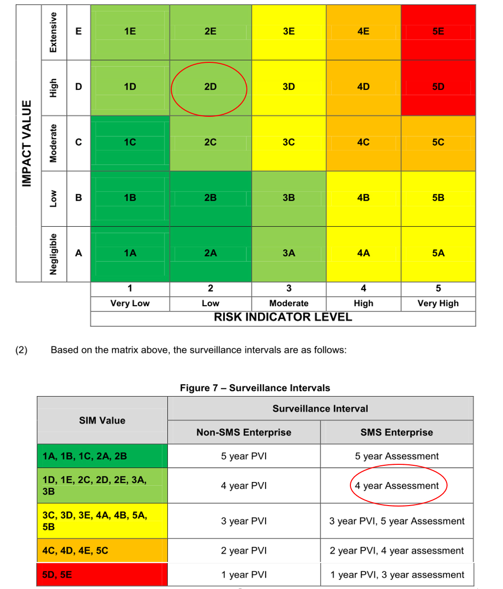
Source: CAD-SUR-008, Issue 02 (29 May 2012), with TSB annotations.
Appendix E – West Wind National Aviation Safety Information Management System risk profile

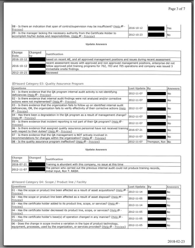
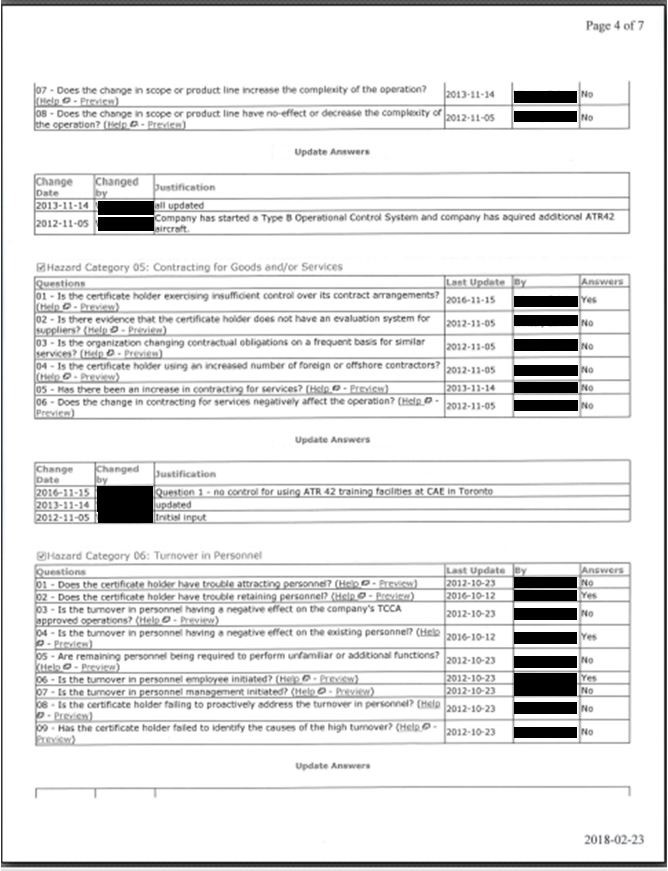

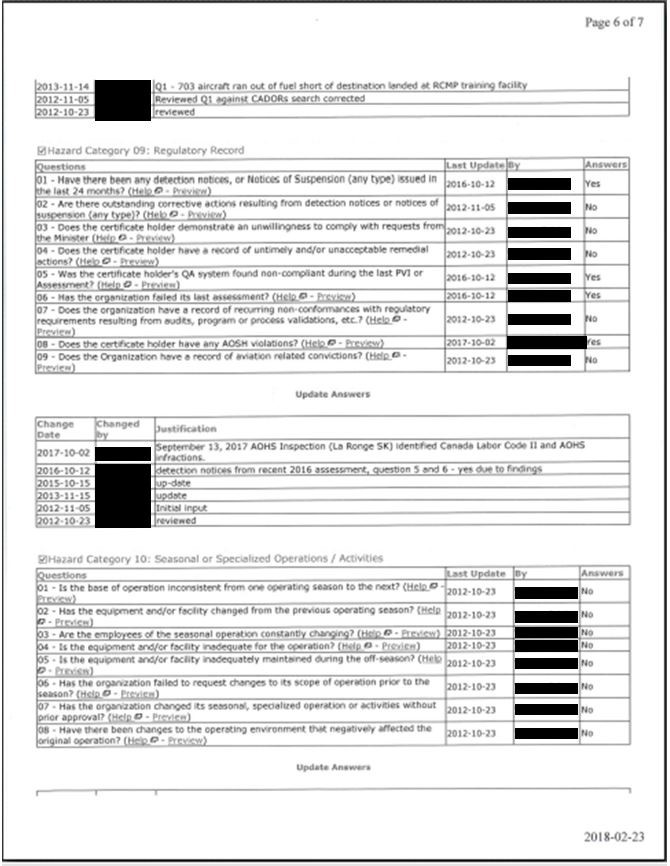

Appendix F – West Wind safety management system reporting form
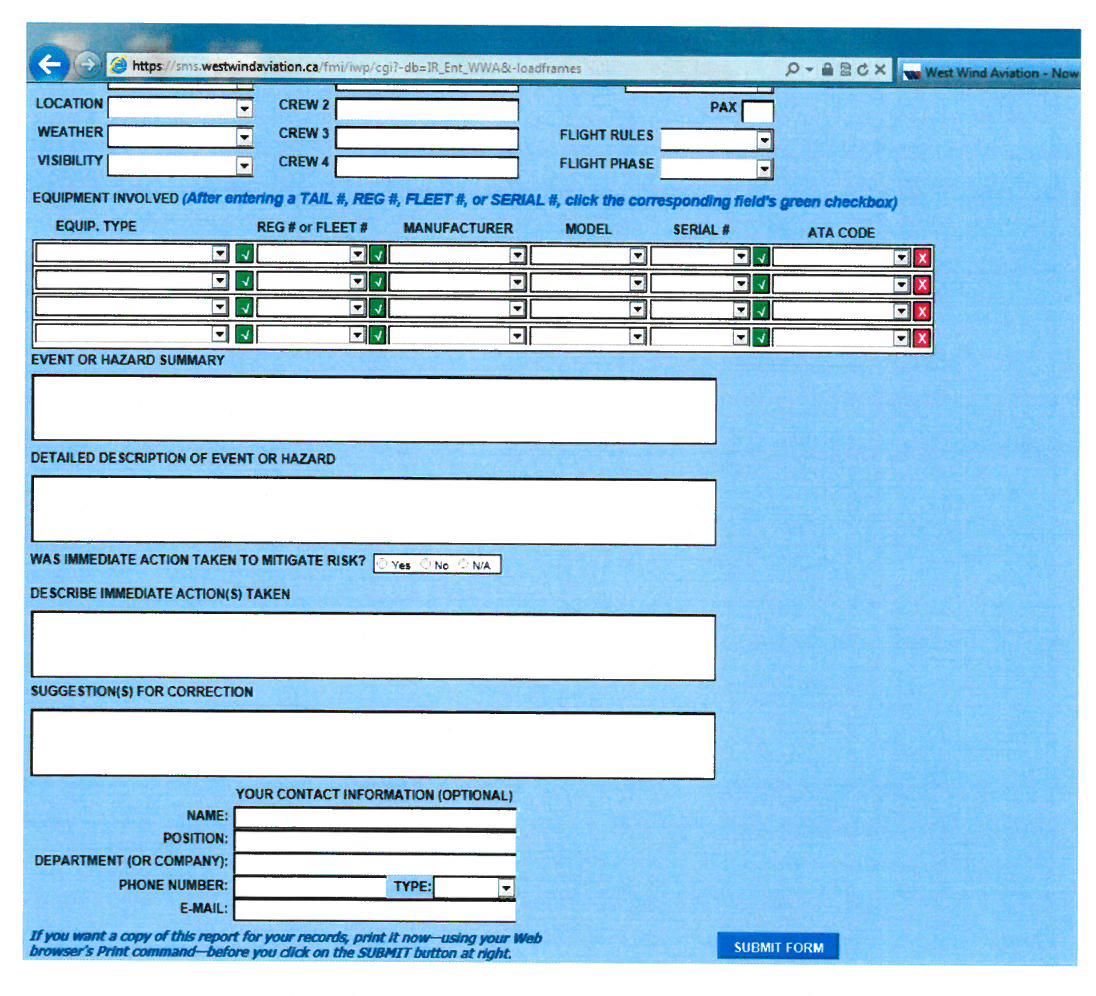
Appendix G – West Wind flowchart for safety reviews (28 June 2018)

Appendix H – TSB investigations with findings related to regulatory oversight and safety management systems
| TSB occurrence number | Finding (finding type) | Safety action taken (reported by Transport Canada) |
|---|---|---|
| A16A0041 | If organizations do not use modern safety management practices and do not have a robust safety culture, then there is an increased risk that hazards will not be identified and mitigated. (Risk) | None reported. |
| A15P0217 | Because the processes described in Helijet International Inc.’s, safety management system (SMS) were not being used effectively, the SMS did not help the company identify and mitigate the risks associated with its night medical evacuation operations. (Cause and Contributing) At the time of the occurrence, there was a lack of resources and training dedicated to the company’s SMS, limiting its effectiveness in mitigating the risks in night operations. (Cause and Contributing) If identified hazards are not captured by a company's SMS, they may go unaddressed, increasing the risk of accidents. (Risk) |
None reported. |
| A15A0054 | If organizations do not use modern safety management practices, then there is an increased risk that hazards will not be identified and risks will not be mitigated. (Risk) If an organization’s safety culture does not fully promote the goals of a safety management system, then it is unlikely that it will be effective in reducing risk. (Risk) |
None reported. |
| A15Q0120 | Unless safety management systems are required, assessed, and monitored by Transport Canada in order to ensure continual improvement, there is an increased risk that companies will not be able to identify and effectively mitigate the hazards involved in their operations. (Risk) | None reported. |
| A14P0132 | An understaffed management structure during organizational changes likely led to excessive workload for existing managers. This contributed to risks, contained within the standard operating procedures, not being addressed through the operator’s safety management system, resulting in continued aircraft operations below published minimum airspeed limitations. (Cause and Contributing) If organizations do not maintain the necessary management resources to oversee effective safety management practices, long-term efforts may dissipate, resulting in the risk of unsafe practices persisting in flight operations. (Risk) |
None reported. |
| A14A0067 | If Transport Canada does not adopt a balanced approach that combines thorough inspections for compliance with audits of safety management processes, unsafe operating practices may not be identified, thereby increasing the risk of accidents. (Risk) | None reported. |
| A13H0002 | If identified regulatory surveillance intervals are not respected, then there is an increased likelihood that systemic deficiencies that could increase risk will go unidentified and unaddressed. (Risk) If findings are overly general, it increases the scope of possible corrective actions and makes it more difficult for the regulator to assess whether the underlying deficiency is addressed through the corrective action plan, increasing the risk that safety deficiencies will remain unaddressed. (Risk) If Transport Canada does not take action to require operators to respect corrective action plan implementation timeframes, there is a risk that safety deficiencies will not be corrected in a timely manner. (Risk) |
None reported. |
| A13H0001 | If safety issues are not reported formally through a company’s safety reporting system, there is a risk that hazards will not be managed effectively. (Risk) | None reported. |
| A13Q0098 | If Transport Canada does not take into consideration the combined knowledge and experience of a new operator’s management team, there is a risk that the operator will lack the skills necessary to ensure the safety of flight operations. (Risk) If process inspections carried out by Transport Canada do not examine factors related to a recent occurrence, there is a risk that those hazardous conditions will go undetected and will persist. (Risk) |
None reported. |
| A13W0120 | The operator’s safety management system was ineffective at identifying and correcting unsafe operating practices. (Cause and Contributing) Transport Canada’s surveillance activities did not identify the operator's unsafe operating practices related to weight and balance and net take-off flight path calculations. Consequently, these unsafe practices persisted. (Cause and Contributing) If Transport Canada does not adopt a balanced approach that combines inspections for compliance with audits of safety management processes, unsafe operating practices may not be identified, thereby increasing the risk of accidents. (Risk) |
None reported. |
| A12Q0216 | If Transport Canada’s oversight is dependent on the effectiveness of a company’s safety management system’s reporting of safety issues, there is a risk that important issues will be missed. (Risk) | None reported. |
| A12W0031 | If adequate surveillance is not maintained by Transport Canada, there is an increased risk that operator safety deficiencies will not be identified. (Risk) | None reported. |
| A11O0031 | During the transition to safety management systems, Transport Canada must recognize that operators may not always identify and mitigate hazards and adjust its oversight activities to be commensurate with the maturity of the operator’s safety management system. (Other) | None reported. |
| A10Q0117 | The action taken by TC did not have the desired outcomes to ensure regulatory compliance; consequently, unsafe practices persisted. (Cause and Contributing) | None reported. |
| A10Q0098 | The significant measures taken by TC did not have the expected results to ensure compliance with the regulations, and, consequently, unsafe practices persisted. (Cause and Contributing) | Transport Canada has made significant changes to its surveillance program. These changes include updates to the methods used for surveillance planning and the introduction of tools that provide an improved capacity for the monitoring and analysis of risk indicators within the aviation system. |
| A07C0001 | Transport Canada (TC) Prairie and Northern Region (PNR) management practices regarding the June 2006 replacement of the regional combined audit program, in order to manage safety management system (SMS) workload, did not conform to TC’s risk management decision-making policies. Reallocation of resources without assessment of risk could result in undetected regulatory non-compliance. (Risk) Although TC safety oversight processes identified the existence of supervisory deficiencies within TWA, the extent of the deficiencies was not fully appreciated by the PNR managers because of the limitations of the oversight system in place at that time. (Risk) |
None reported. |
Appendix I – West Wind threat and error management briefing reference card
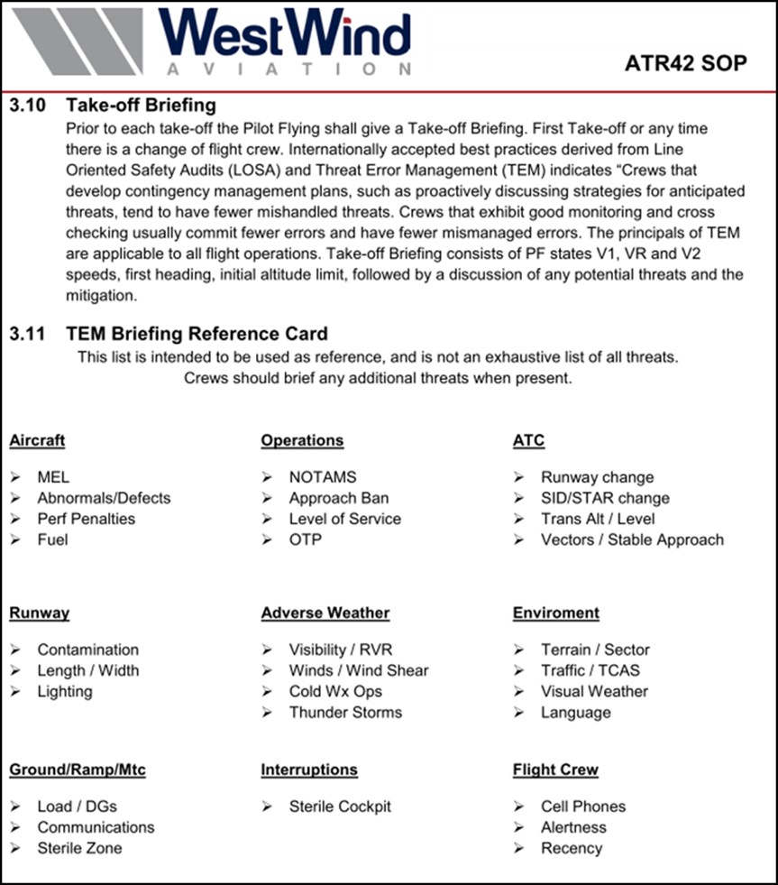
Source: West Wind Aviation L.P., ATR 42 SOP (17 December 2016), p. 58.
Appendix J – Similar occurrences in Canada involving contaminated critical surfaces during takeoff
| Occurrence number | Date | Aircraft type | Location | Comments |
|---|---|---|---|---|
| N/A | 1989-03-10 | Fokker F-28 | Dryden, ON | Accident. Commercial operation. Contaminated critical surfaces before takeoff. Collision with terrain after takeoff. 24 fatalities. Moshansky Commission of Inquiry made many recommendations. |
| A98Q0057 | 1998-04-25 | DHC-8-102 | Québec, QC | Incident. Commercial operation. Contamination before takeoff froze and resulted in jammed elevators during cruise. No injuries. |
| A98Q0194 | 1998-12-07 | Britten-Norman BN2A-26 | Point-Lebel, QC | Accident. Commercial operation. Contaminated critical surfaces before takeoff. Loss of control and collision with terrain after takeoff. 6 fatalities, 1 person missing, 3 serious injuries. |
| A99P0181 | 1999-12-28 | Cessna 208 | Abbotsford, BC | Accident. Private operation. Contaminated critical surfaces before takeoff. Loss of control and collision with terrain after takeoff. 3 serious injuries, 3 minor injuries. |
| A03O0088 | 2003-04-07 | Found FBA-2C1 | Lake Temagami, ON | Accident. Private operation. Contamination before takeoff, loss of control and collision with terrain after takeoff. 2 fatalities. |
| A03O0302 | 2003-11-04 | DHC-8-102 | Ottawa, ON | Incident. Commercial operation. Aircraft de-iced before takeoff. Control restrictions during takeoff, rejected takeoff. No injuries. |
| A04H0001 | 2004-01-17 | Cessna 208B | Pelee Island, ON | Accident. Commercial operation. Contaminated critical surfaces before takeoff, loss of control and collision with terrain after takeoff. 10 fatalities. |
| A09C0017 | 2009-02-04 | DHC-6 | La Ronge, SK | Accident. Commercial operation. Contaminated critical surfaces before takeoff. Loss of control and collision with terrain after takeoff. 7 minor injuries. |
| A12C0154 | 2012-11-18 | Cessna 208B | Snow Lake, MB | Accident. Commercial operation. Contaminated critical surfaces before takeoff, loss of control and collision with terrain after takeoff. 1 fatality, 7 serious injuries. |
| A13W0201 | 2013-12-17 | Boeing 737-300 | Fort MacKay / Albian Aerodrome, AB | Incident. Commercial operation. Aircraft de-iced and anti-iced before departure. Insufficient quantity of Type IV fluid used for anti-icing. Difficulty controlling the aircraft after takeoff. No injuries. The TSB issued an aviation safety advisory to Transport Canada on 10 September 2014. |
Appendix K – Similar occurrences outside Canada involving contaminated critical surfaces during takeoff
| Occurrence number | Date | Aircraft type | Location | Comments |
|---|---|---|---|---|
| DCA82AA011 | 1982-01-13 | B737 | Washington, D.C. | Contaminated critical surfaces. 78 fatalities. |
| DCA88MA004 | 1987-11-15 | DC-9-14 | Denver, Colorado | Contaminated critical surfaces. 28 fatalities. |
| A02F0002 | 2002-01-04 | CL600-2B16 | Birmingham, UK | Frost contamination before takeoff. 5 fatalities. |
| A04F0207 | 2004-11-28 | CL60 | Montrose, Colorado | Contaminated critical surfaces before takeoff. 3 fatalities, 3 seriously injured. |
| A04F0202 | 2004-11-21 | CL600-2B19 | Baotou, China | Contaminated critical surfaces before takeoff. 53 fatalities. |
| A05F0023 | 2005-01-31 | Cessna 208 | Helsinki, Finland | Contaminated critical surfaces before takeoff. |
| N/A | 2007-01-25 | Fokker 100 | Pau, France | Contaminated critical surfaces before takeoff. |
| A08F0020 | 2008-01-31 | CL-600-2B19 | Oslo, Norway | Leading-edge contamination during takeoff run. No injuries. |
| A08F0026 | 2008-02-14 | CL-600-2B19 | Yerevan, Armenia | Contaminated critical surfaces before takeoff. 7 serious injuries. |
| N/A | 2008-04-09 | BAe Jetstream 41 | Aberdeen, UK | Contaminated critical surfaces before takeoff. Incident. No injuries. |
| A12F0033 | 2012-04-02 | ATR72-201 | Tyumen, Russia | Contaminated critical surfaces before takeoff. 33 fatalities. |
| N/A | 2013-03-04 | Beechcraft Premier 1A | Annemasse, France | Contaminated critical surfaces before takeoff. 2 fatalities. |
| N/A | 2016-03-04 | ATR 72-212A | Manchester, UK | Contaminated critical surfaces before takeoff. Incident. No injuries. |
Appendix L – TSB pilot questionnaire
Q1. When I am at a remote airport, I have access to ground equipment that enables effective inspection of all of the aircraft’s critical surfaces for contamination.
Never / Rarely / Sometimes / Usually / Always / Does not apply
Q2. When I am at a remote airport, I have access to ground equipment that enables adequate de‑icing of the aircraft’s critical surfaces before takeoff.
Never / Rarely / Sometimes / Usually / Always / Does not apply
Q3. When I am at a remote airport, I have access to ground equipment that enables adequate anti-icing of the aircraft’s critical surfaces before takeoff.
Never / Rarely / Sometimes / Usually / Always / Does not apply
Q4. When I am inbound to a remote airport where de-icing and anti-icing equipment is known to be inadequate and ground icing conditions exist or are forecast at that airport, I will divert to an alternate airport.
Never / Rarely / Sometimes / Usually / Always / Does not apply
Q5. When I am inbound to a remote airport where de-icing and anti-icing equipment is known to be inadequate and icing conditions are encountered in flight and residual ice remains on the aircraft’s critical surfaces, I will divert to an alternate airport.
Never / Rarely / Sometimes / Usually / Always / Does not apply
Q6. I am able to have my aircraft de-iced effectively at remote airports.
Never / Rarely / Sometimes / Usually / Always / Does not apply
Q7. I am able to have my aircraft anti-iced effectively at remote airports.
Never / Rarely / Sometimes / Usually / Always / Does not apply
Q8A. The operator I fly for has a ground icing operations program.
Yes / No
[If Yes to Q8A] Q8B. My company's ground icing program include directives on what to do if anti-icing and/or de-icing equipment and personnel are not available.
Yes / No
[If Yes to Q8A] Q8C. My company's ground icing program is effective?
Yes / No
[If Yes to Q8A] Q8D. Please describe how your company's ground icing program is effective or ineffective.
Q9. In the past year, I have received initial or recurrent training in aircraft surface contamination.
Yes / No
Q10. As a result of my initial or recurrent training, I understand the effects of aircraft critical surface contamination.
Strongly disagree / Disagree / Neither agree nor disagree / Agree / Strongly agree
Q12. In the past 5 years, I have seen pilots take off with contaminated critical surfaces.
Yes / No
[If Yes to Q12] Q12Y. Please give one or more examples. It would be useful if you could include some or all of the following information, but please do not include information that could identify individuals or operators.
- Aircraft type
- Circumstances
- Degree of contamination
- Availability and adequacy of de-icing and anti-icing equipment
- Your knowledge of any negative consequences
- Any other factors you know of that influenced pilot decision making during the events you witnessed.
Q13. Under which operations category do you typically fly?
- Private Operators (CARs subpart 604)
- Aerial work (CARs subpart 702)
- Air taxi (CARs subpart 703)
- Commuter (CARs subpart 704)
- Airline (CARs subpart 705)
- Other (please specify)
Q14. Please select from the dropdown list the primary aircraft type you currently fly:
- Piston single engine
- Piston multi engine ≤ 12 500 lbs
- Piston multi engine > 12 500 lbs
- CL-215
- DC-3
- Turboprop single engine
- PC-12
- C-208
- Turboprop multi engine ≤ 12 500 lbs
- Beech 90
- Beech 99
- Beech 100
- Beech 200
- Beech 300
- DHC-6
- MU2
- SA226
- Turboprop multi engine > 12 500 lbs to 25 000 lbs
- Beech 1900
- SA-227
- Turboprop multi engine > 25 000 lbs
- ATR 42/72
- CL-415
- DHC-8
- HS-748
- Jet multi engine ≤ 70 000 lbs
- Jet multi engine > 70 000 lbs
Q15. What type of pilot licence do you currently hold?
- Airline transport pilot license (ATPL)
- Commercial pilot license (CPL)
- Foreign licence validation certificate (FLVC)
- Other (please specify)
Q16. What is your total flight time hours on all aircraft types?
Q17. What is your total pilot-in-command flight time hours?
Q18. How many years have you been employed as a pilot?
Q19. Of your total experience as a pilot, how many winter seasons did you conduct flights to remote airports?
Q20. How many years have you been employed by your current employer?
Q21. What is your primary role at the operator you fly for?
- Management pilot
- Check and/or training pilot
- Line pilot
Q22. What crew position do you hold on the aircraft type you currently fly most frequently?
- Captain
- First officer
- Other (please specify)
Q23. What is your total flight time hours on the aircraft type you currently fly most frequently?
Q24. What is your pilot-in-command flight time hours on the aircraft type you currently fly most frequently?
Appendix M – Summary of TSB pilot questionnaire responses
Responses to questions 1 to 7 and 10 were on 5-point Likert scales. These were coded for analysis using a scale of 0 to 4, and the responses that indicated “does not apply” were assigned a null value.
Question 1: When I am at a remote airport, I have access to ground equipment that enables effective inspection of all of the aircraft’s critical surfaces for contamination.
| 0. Never | 1. Rarely | 2. Sometimes | 3. Usually | 4. Always | Does not apply |
|---|---|---|---|---|---|
| 26 (4%) | 177 (27%) | 174 (27%) | 178 (27%) | 96 (15%) | 4 (1%) |
- Mean = 2.22
- Median = 2.00
- Mode = 3.00
- Standard deviation = 1.12
- Variance = 1.25
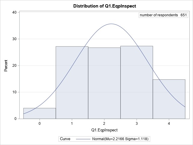
Almost one-third (31%) of respondents indicated that they never or rarely have access to ground equipment that enables effective inspection of the aircraft’s critical surfaces. A further 27% replied they sometimes had access to the equipment. Less than half (42%) indicated they usually or always have access to such equipment.
Question 2: When I am at a remote airport, I have access to ground equipment that enables adequate de‑icing of the aircraft’s critical surfaces before takeoff.
| 0. Never | 1. Rarely | 2. Sometimes | 3. Usually | 4. Always | Does not apply |
|---|---|---|---|---|---|
| 41 (6%) | 191 (29%) | 177 (27%) | 165 (25%) | 77 (12%) | 4 (1%) |
- Mean = 2.07
- Median = 2.00
- Mode = 1.00
- Standard deviation = 1.13
- Variance = 1.27
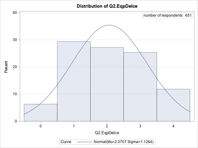
More than one-third (35%) of respondents indicated that they never or rarely have access to ground equipment than enables adequate de-icing of their aircraft at remote airports. A further 27% stated they sometimes had access to the equipment. Only 37% indicated they usually or always have access to necessary equipment.
Question 3: When I am at a remote airport, I have access to ground equipment that enables adequate anti-icing of the aircraft’s critical surfaces before takeoff.
| 0. Never | 1. Rarely | 2. Sometimes | 3. Usually | 4. Always | Does not apply |
|---|---|---|---|---|---|
| 207 (32%) | 206 (31%) | 98 (15%) | 83 (13%) | 45 (7%) | 16 (2%) |
- Mean = 1.30
- Median = 1.00
- Mode = 0.00
- Standard deviation = 1.24
- Variance = 1.54

Almost two-thirds of respondents (63%) reported they never or rarely have access to equipment for anti-icing their aircraft at remote airports, and a further 15% indicated they sometimes have access to this equipment. Only 20% of respondents said they usually or always had adequate anti-icing equipment available.
Question 4: When I am inbound to a remote airport where de-icing and anti-icing equipment is known to be inadequate and ground icing conditions exist or are forecast at that airport, I will divert to an alternate airport.
| 0. Never | 1. Rarely | 2. Sometimes | 3. Usually | 4. Always | Does not apply |
|---|---|---|---|---|---|
| 49 (7%) | 120 (18%) | 120 (18%) | 159 (24%) | 187 (29%) | 20 (3%) |
- Mean = 2.50
- Median = 3.00
- Mode = 4.00
- Standard deviation = 1.30
- Variance = 1.68
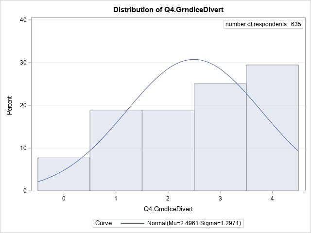
When presented a statement about diverting from an airport with inadequate equipment and ground icing conditions, 25% of respondents replied they would never or rarely divert to an alternate airport, and 18% said they would sometimes divert. Most (53%) indicated they would usually or always divert in this situation.
Question 5. When I am inbound to a remote airport where de-icing and anti-icing equipment is known to be inadequate, icing conditions are encountered in flight, and residual ice remains on the aircraft’s critical surfaces, I will divert to an alternate airport.
| 0. Never | 1. Rarely | 2. Sometimes | 3. Usually | 4. Always | Does not apply |
|---|---|---|---|---|---|
| 86 (13%) | 172 (26%) | 120 (18%) | 116 (18%) | 137 (21%) | 24 (4%) |
- Mean = 2.07
- Median = 2.00
- Mode = 1.00
- Standard deviation = 1.37
- Variance = 1.87
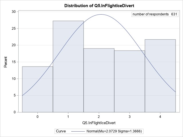
Responses to a similar statement about locations where ground equipment is known to be inadequate, coupled with in-flight icing and contaminated surfaces, followed the pattern seen in responses to Question 4, although slightly fewer respondents stated that they would divert:
- 39% of respondents indicated they would never or rarely divert in this situation;
- a further 18% said they would sometimes divert; and
- 39% said they would usually or always divert.
Question 6. I am able to have my aircraft de-iced effectively at remote airports.
| 0. Never | 1. Rarely | 2. Sometimes | 3. Usually | 4. Always | Does not apply |
|---|---|---|---|---|---|
| 37 (6%) | 216 (33%) | 152 (23%) | 180 (27%) | 65 (10%) | 5 (1%) |
- Mean = 2.03
- Median = 2.00
- Mode = 1.00
- Standard deviation = 1.11
- Variance = 1.24
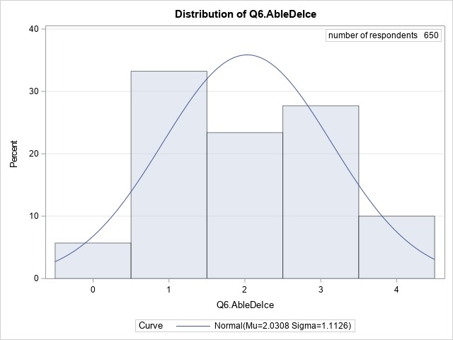
The responses suggest that de-icing at remote airports can be challenging:
- 39% of respondents indicated that they are never or rarely able to have their aircraft de-iced;
- another 23% responded they are sometimes able to do so; and
- 37% said they are usually or always able to have their aircraft de-iced at remote airports.
Question 7. I am able to have my aircraft anti-iced effectively at remote airports.
| 0. Never | 1. Rarely | 2. Sometimes | 3. Usually | 4. Always | Does not apply |
|---|---|---|---|---|---|
| 231 (35%) | 213 (33%) | 89 (14%) | 68 (10%) | 29 (4%) | 25 (4%) |
- Mean = 1.13
- Median = 1.00
- Mode = 0.00
- Standard deviation = 1.16
- Variance = 1.34
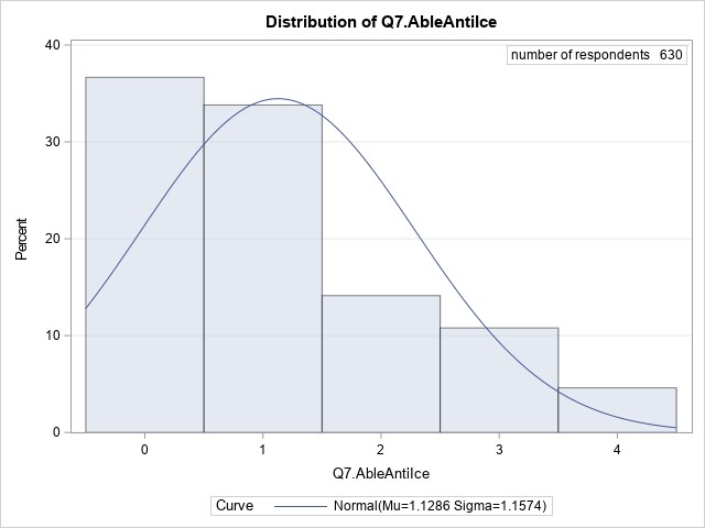
The responses indicate that anti-icing capability at remote airports is less available than de‑icing. More than two-thirds of respondents (68%) said they were never or rarely able to have their aircraft anti-iced effectively, and a further 14% reported they could sometimes do so. Only 14% of respondents said they were usually or always able to anti-ice at remote airports.
Question 8A. The operator I fly for has a ground icing operations program.
| 0. No | 1. Yes | n = |
|---|---|---|
| 56 (9%) | 599 (91%) | 655 (100%) |
- Mean = 0.91
- Median = 1.00
- Mode = 1.00
- Standard deviation = 0.28
- Variance = 0.08

Most respondents (91%), indicated their operator has a ground icing operations program in place.
Question 8B. My company's ground icing program includes directives on what to do if anti-icing and/or de-icing equipment and personnel are not available.
| 0. No | 1. Yes | n = |
|---|---|---|
| 188 (32%) | 406 (68%) | 594 (100%) |
- Mean = 0.68
- Median = 1.00
- Mode = 1.00
- Standard deviation = 0.47
- Variance = 0.22
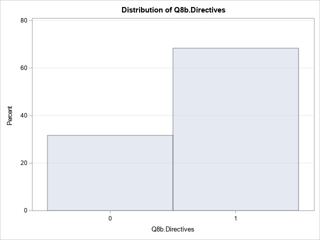
More than two-thirds (68%) of responses to this question indicated the respondents’ company’s ground icing program included directives on what to do if anti-icing or de-icing facilities or services are not available. About one-third (32%) reported their company’s program did not provide such directives.
Question 8C. My company's ground icing program is effective.
| 0. No | 1. Yes | n = |
|---|---|---|
| 196 (33%) | 396 (67%) | 592 (100%) |
- Mean = 0.67
- Median = 1.00
- Mode = 1.00
- Standard deviation = 0.47
- Variance = 0.22

About two-thirds (67%) of respondents answering this question indicated that their company’s ground icing program is effective, while the remaining one-third (33%) disagreed and indicated their company’s program was not effective.
Question 8D. Please describe how your company's ground icing program is effective or ineffective.
The individualized responses for this item were reviewed in the context of the investigation; however, the responses are not included here, due to the required protection of certain information.
Question 9. In the past year, I have received initial or recurrent training in aircraft surface contamination.
| 0. No | 1. Yes | n = |
|---|---|---|
| 9 (1%) | 646 (99%) | 655 (100%) |
- Mean = 0.99
- Median = 1.00
- Mode = 1.00
- Standard deviation = 0.12
- Variance = 0.01
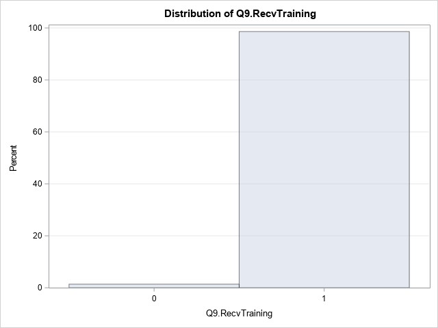
Almost all respondents (99%) reported that they had received training in aircraft surface contamination in the past year.
Question 10. As a result of my initial or recurrent training, I understand the effects of aircraft critical-surface contamination.
| 0. Strongly disagree | 1. Disagree | 2. Neither agree nor disagree | 3. Agree | 4. Strongly agree | n = |
|---|---|---|---|---|---|
| 16 (2%) | 5 (1%) | 14 (2%) | 216 (33%) | 395 (61%) | 646 (100%) |
- Mean = 3.50
- Median = 4.00
- Mode = 4.00
- Standard deviation = 0.80
- Variance = 0.64
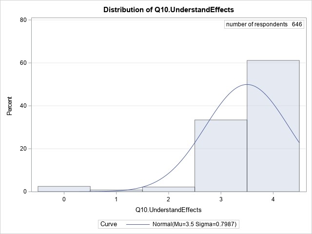
Most respondents (94%) strongly agreed or agreed that they understand the effects of aircraft critical-surface contamination as a result of their training, while 2% said they neither agreed nor disagreed. A small group of respondents (3%) responded that they strongly disagreed or disagreed with this statement.
Question 11. In the past 5 years, I have seen pilots take off with contaminated critical surfaces.
| 0. No | 1. Yes | n = |
|---|---|---|
| 171 (26%) | 484 (74%) | 655 (100%) |
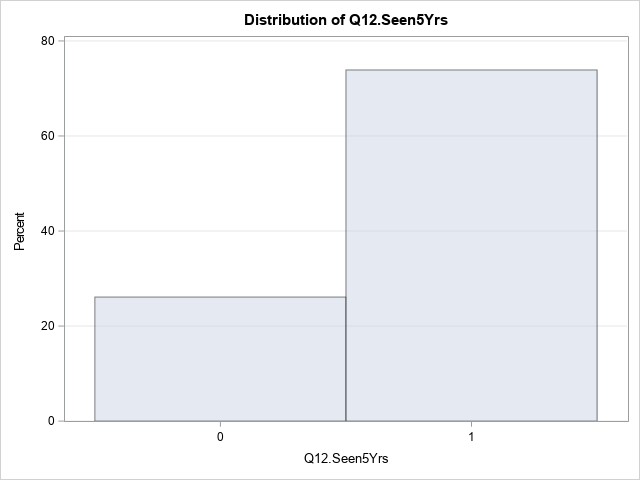
About three-quarters of respondents (74%) indicated that they had witnessed pilots take off with contaminated critical surfaces in the past 5 years. Only 25% of respondents reported they had not.
Question 12Y. [This question was presented only to respondents who answered yes to Question 12, and offered an unlimited text field for response.] Please give one or more examples. It would be useful if you could include some or all of the following information, but please do not include information that could identify individuals or operators.
- Aircraft type
- Circumstances
- Degree of contamination
- Availability and adequacy of de-icing and anti-icing equipment
- Your knowledge of any negative consequences
- Any other factors you know of that influenced pilot decision making during the events you witnessed.
Of the 484 respondents who answered “yes” to Question 12 above, 396 provided further information about the events they had seen.
About three-quarters (73%) of these 396 respondents made no mention of negative consequences associated with events they had seen, 24% reported they had not seen any adverse consequences, and only a small number (4%, or 14 of 396 responses with details) reported they knew of negative consequences such as reduced climb performance or difficulty in controlling the aircraft.
The following table summarizes responses to Question 12Y.
| Number of responses | ||
|---|---|---|
| Question 12 Y all responses | Completed the survey | 655 (100%) |
| Witnessed an aircraft take off in the past five years with contaminated critical surfaces | 484 | |
| Provided details | 396 | |
| Aircraft type (Many responses that provided details reported multiple aircraft types, consequently sum of responses is > 282 and sum of proportions is > 100%) |
Responses that identified one or more aircraft types or operation types | 282 [100%] |
| Reponses that identified aircraft types common in air taxi operations | 169 [60%] | |
| Reponses that identified aircraft types common in commuter operations | 120 [43%] | |
| Responses that identified aircraft types common in airliner operations | 146 [52%] | |
| Adverse consequences | Observed adverse consequences of contaminated surfaces. | 14 (4%) |
| Did not observe any adverse consequences | 96 (24%) | |
| No mention of adverse consequences | 288 (73%) | |
| Equipment | Mentioned equipment not available, or inaccessible. This includes a total lack of equipment, or else a statement that existing equipment is locked away, frozen into snowbanks, or similarly unavailable. | 84 (21%) |
| Mentioned equipment available and accessible, but insufficient for task, or unserviceable. | 147 (37%) | |
| Mentioned equipment available, but not used. (Often correlated with the idea that equipment was insufficient for the task.) | 142 (36%) [100%] | |
| Equipment not used due to time pressure | 33 [23%] | |
| Equipment not used due to financial cost | 32 [23%] | |
| Equipment not used for fear of causing or worsening contamination | 20 [14%] | |
| Equipment not used/not available due to competition between operators preventing access to existing equipment at remote airports | 11 [8%] | |
Question 13. Under which operations category do you typically fly?
| CARs 702 Aerial work | CARs 703 Air taxi | CARs 704 Commuter | CARs 705 Airline | CARs 604 Private operator | Other |
|---|---|---|---|---|---|
| 6 (1%) | 207 (32%) | 96 (15%) | 304 (46%) | 22 (3%) | 20 (3%) |
The majority (46%) of respondents indicated they fly in the airline category (CARs 705), almost one-third (32%) indicated air taxi as their primary operational category (CARs 703), and about 15% said they fly in the commuter category (CARs 704). Only 1% of respondents indicated their operations category was aerial work (CARs 702).
A small number of respondents (3%) fly under a private operator certificate (CARs 604). About the same number opted not to pick a single category, but instead wrote in a combination of categories; almost all such responses included air taxi (CARs 703) and commuter (CARs 704) categories, and about half included the airline category (CARs 705).
Question 14. Please select from the dropdown list the primary aircraft type you currently fly.
| Piston single-engine (1) | Piston multi-engine ≤ 12 500 lb (2) | Piston multi-engine > 12 500 lb (3) | Turboprop single-engine (4) | Turboprop multi-engine ≤ 12 500 lb (5) | Turboprop multi-engine > 12 500 lb to 25 000 lb (6) | Turboprop multi-engine > 25 000 lb (7) | Jet multi-engine ≤ 70 000 lb (8) | Jet multi-engine > 70 000 lb (9) |
|---|---|---|---|---|---|---|---|---|
| 5 (1%) | 8 (1%) | 8 (1%) | 60 (9%) | 177 (27%) | 62 (9%) | 216 (33%) | 20 (3%) | 99 (15%) |
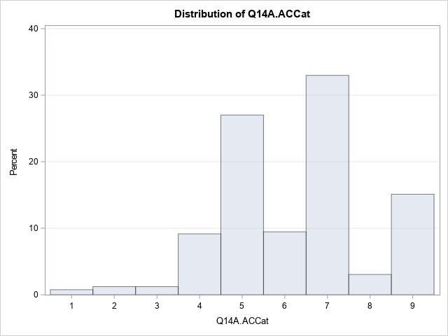
Respondents reported flying a diverse spectrum of aircraft types.
A relatively small number of respondents (3%) fly piston-engine aircraft:
- 1% fly piston-powered single-engine aircraft;
- 1% fly multi-engine aircraft of 12 500 pounds (lb) or less; and
- 1% fly heavy multi-engine aircraft of over 12 500 lb.
Most respondents (79%) fly turboprop aircraft:
- 9% fly single-engine turboprop aircraft;
- 27% fly multi-engine turboprop aircraft of 12 500 lb or less;
- 9% fly multi-engine turboprop aircraft of 12 501 to 25 000 lb; and
- 33% fly multi-engine turboprop aircraft of over 25 000 lb.
The remaining 18% of respondents fly multi-engine jet aircraft:
- 3% fly jets of 70 000 lb or less; and
- 15% fly jets of more than 70 000 lb.
Question 15. What type of pilot licence do you currently hold?
| 1. ATPL | 2. CPL | 3. Other | n = |
|---|---|---|---|
| 493 (75%) | 159 (24%) | 3 (0%) | 655 (100%) |
Three-quarters of respondents (75%) hold an airline transport pilot licence (ATPL). Most of the remainder (24%) hold a commercial pilot licence (CPL), while three respondents (< 1%) hold other licenses.
Question 16. What is your total flight time hours on all aircraft types?
Number of responses that fall in the described categories
| 0 - 1500 hours | 1501 – 5000 hours | 5001 – 10 000 hours | 10 001 + hours |
|---|---|---|---|
| 101 (15%) | 239 (36%) | 158 (24%) | 155 (24%) |
Question 17. What is your total pilot-in-command flight time hours?
Number of responses that fall in the described categories
| 0 - 1500 hours | 1501 – 5000 hours | 5001 – 10 000 hours | 10 001 + hours |
|---|---|---|---|
| 240 (37%) | 211 (32%) | 117 (18%) | 85 (13%) |
Question 18. How many years have you been employed as a pilot?
One-quarter of respondents had been employed 5 years or less, half of the respondents had been employed between 5 and 20 years, and one-quarter had been employed 20 years or more.
- 652 respondents collectively reported 8819 years of employment.
- Of those, 492 pilots having an ATPL accounted for 8151 years of employment, and
- 157 pilots having a CPL accounted for 623 years of employment.
- 3 respondents with licences other than ATPL and CPL reported a total of 45 years of employment.
- Mean = 13.53
- Median = 10.50
- Mode = 5.00
- Standard deviation = 10.74
- Variance = 115.39
- Range = 54.00
- Interquartile range = 15.00
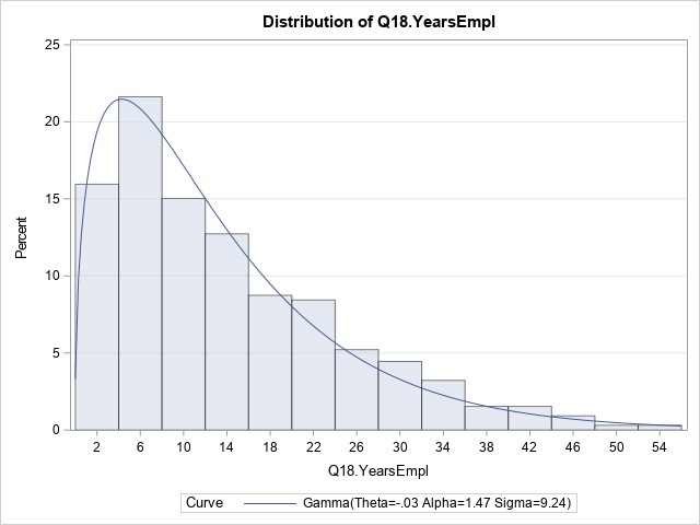
Question 19. Of your total experience as a pilot, how many winter seasons did you conduct flights to remote airports?
One-quarter of respondents had experienced 3 or fewer winter seasons, half of the respondents had experienced between 3 and 13 winter seasons, and one-quarter had experienced 13 or more winter seasons.
- 655 respondents collectively reported 5997 winter seasons during which they conducted flights to remote airports.
- Of those, 493 pilots having an ATPL accounted for 5540 winter seasons of experience, and
- 159 pilots having a CPL accounted for 432 winter seasons of experience.
- 3 respondents with licences other than ATPL and CPL reported an additional 25 winter seasons of experience.
- Mean = 9.15
- Median = 6.00
- Mode = 1.00
- Standard deviation = 8.73
- Variance = 76.17
- Range = 54.00
- Interquartile range = 10.00
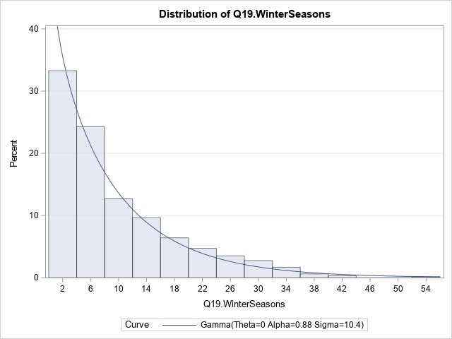
Question 20. How many years have you been employed by your current employer?
One-quarter of respondents had spent 1.5 years or less with their current employer, half of respondents had spent between 1.5 and 10 years, and one-quarter had spent 10 years or more with their current employer.
- 655 respondents collectively reported having 4419 years employment with their current employer.
- Of those, 493 pilots having an ATPL accounted for 4036 years employment with their current employers, and
- 159 pilots having a CPL accounted for 379 years with their current employers.
- 3 respondents with licences other than ATPL and CPL reported an additional 4 years with their current employers.
- Mean = 6.76
- Median = 4.00
- Mode = 1.00
- Standard deviation = 7.29
- Variance = 53.16
- Range = 53.00
- Interquartile range = 8.50
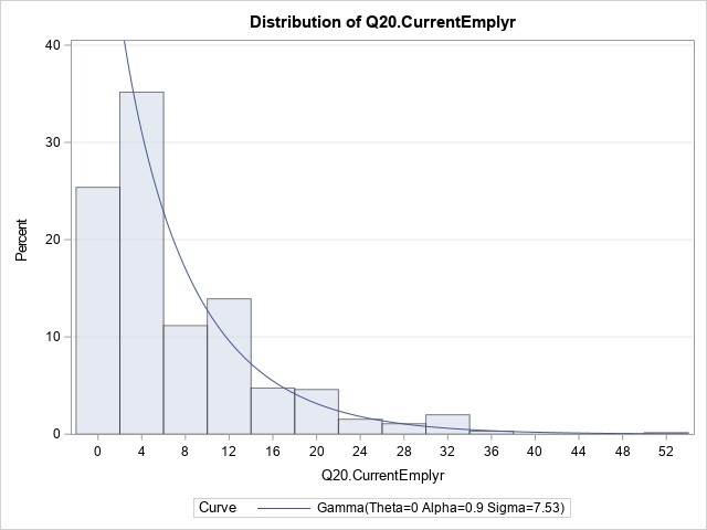
Question 21. What is your primary role at the operator you fly for?
| 1. Line pilot | 2. Check/training pilot | 3. Management pilot | n = |
|---|---|---|---|
| 524 (80%) | 91 (14%) | 40 (6%) | 655 (100%) |
Most respondents (80%) are line pilots with their organization, 14% said they are check or training pilots, and 6% are management pilots.
Question 22. What crew position do you hold on the aircraft type you currently fly most frequently?
| 1. Captain | 2. First officer | 3. Other | n = |
|---|---|---|---|
| 437 (67%) | 214 (33%) | 4 (1%) | 655 (100%) |
Two-thirds of respondents indicated they hold a captain position on the aircraft type they fly most frequently, and 33% stated they fly as a First officer.
Q23. What is your total flight time hours on the aircraft type you currently fly most frequently?
Number of responses that fall in the described categories
| 0 - 1000 hours | 1001 – 2500 hours | 2501 – 7500 hours | 7500 + hours |
|---|---|---|---|
| 287 (44%) | 164 (25%) | 152 (23%) | 50 (8%) |
Q24. What is your pilot-in-command flight time hours on the aircraft type you currently fly most frequently?
Number of responses that fall in the described categories
| 0 hours | 1 - 1000 hours | 1001 – 2500 hours | 2501 – 7500 hours | 7500 + hours |
|---|---|---|---|---|
| 196 (30%) | 226 (35%) | 95 (15%) | 111 (17%) | 25 (4%) |
Glossary
- AFM
- Airplane Flight Manual
- AGL
- above ground level
- AOA
- angle of attack
- APM
- aircraft performance monitoring
- ASL
- above sea level
- ATC
- air traffic control
- ATF
- aerodrome traffic frequency
- ATPL
- airline transport pilot licence
- ATR
- Avions de Transport Régional
- AWOS
- automated weather observation system
- CA
- convening authority
- CAD
- Civil Aviation Directive
- CAP
- corrective action plan
- CARs
- Canadian Aviation Regulations
- CASS
- Commercial Air Services Standards
- CBR
- California bearing ratio
- CMM
- Component Maintenance Manual
- COM
- Company Operations Manual
- CRM
- crew resource management
- CVR
- cockpit voice recorder
- CYNL
- Points North Landing Airport
- CYPA
- Prince Albert (Glass Field) Airport
- CYSF
- Stony Rapids Airport
- CYXE
- Saskatoon/John G. Diefenbaker International Airport
- CZFD
- Fond-du-Lac Airport
- CZWL
- Wollaston Lake Airport
- DFO
- Director of Flight Operations
- DZ
- drizzle
- EGPWS
- enhanced ground proximity warning system
- EM
- enhanced monitoring
- FA
- flight attendant
- FAA
- Federal Aviation Administration
- FAR 25
- FAA, Code of Federal Regulations, Title 14: Aeronautics and Space, Part 25: Airworthiness Standards: Transport Category Airplanes
- FCOM
- Flight Crew Operating Manual
- FDM
- flight data monitoring
- FDR
- flight data recorder
- FL
- flight level
- FMS
- flight management system
- FO
- first officer
- FOQA
- flight operational quality assurance
- FZBR
- freezing mist
- FZDZ
- freezing drizzle
- FZRA
- freezing rain
- FZFG
- freezing fog
- FZUP
- freezing – unknown precipitation
- GFA
- graphic area forecast
- GIOP
- ground icing operations program
- ICAO
- International Civil Aviation Organization
- inHg
- inches of mercury
- IPB
- internal process bulletin
- KIAS
- knots indicated airspeed
- L1
- front emergency exit (left)
- L2
- rear entry door (left)
- LOSA
- line operations safety audit
- MANOBS
- Manual of Surface Weather Observation Standards
- METAR
- aerodrome routine meteorological report
- NASIMS
- National Aviation Safety Information Management System
- NCAMX
- National Civil Aviation Management Executive Committee
- NM
- nautical mile
- NOO
- National Oversight Office
- NOS
- Notice of Suspension
- OAB
- Oversight Advisory Board
- OFP
- operational flight plan
- ORM
- operational risk management
- PF
- pilot flying
- PI
- process inspection
- PIC
- pilot-in-command
- PNF
- pilot not flying
- PVI
- program validation inspection
- R1
- front emergency exit (right)
- R2
- rear service door (right)
- RA
- rain
- RCMP
- Royal Canadian Mounted Police
- RIN
- risk-indicator number
- SI
- staff instruction
- SM
- statute mile
- SMS
- safety management system
- SOP
- standard operating procedure
- T
- true
- TAF
- aerodrome forecast
- TC
- Transport Canada
- TCCA
- Transport Canada Civil Aviation
- TEM
- threat and error management