Engine Failure - Hard Landing
VIH Helicopter Ltd.
Bell 407 (Helicoper) C-GNVI
Blue River, British Columbia
The Transportation Safety Board of Canada (TSB) investigated this occurrence for the purpose of advancing transportation safety. It is not the function of the Board to assign fault or determine civil or criminal liability. This report is not created for use in the context of legal, disciplinary or other proceedings. See Ownership and use of content. Masculine pronouns and position titles may be used to signify all genders to comply with the Canadian Transportation Accident Investigation and Safety Board Act (S.C. 1989, c. 3).
Summary
The Bell 407 helicopter (registration C-GNVI, serial number 53847), operated by VIH Helicopters Ltd., was transporting 5 skiers and 1 guide to a drop-off site at about 6000 feet above sea level, 8 nautical miles southeast of Blue River, British Columbia. At 1035, Pacific Standard Time, as the helicopter neared the site, a bang and shudder occurred, immediately followed by the low rotor rpm and engine-out horns. Moments later, the helicopter landed heavily and the pilot and the ski guide, respectively seated in the right and left front seats, sustained back injuries. The 5 skiers seated in the middle and rear seats were not injured. The helicopter was substantially damaged. The emergency locator transmitter activated automatically on impact and was manually shut off by the pilot once help arrived. There was no fire.
Other Factual Information
Accident Site
Immediately prior to the power loss the helicopter was climbing at about 65 knots, about 200 feet above ground level (agl) over rising terrain. The intended landing site was about 100 feet vertically above and 700 feet laterally from the helicopter when a bang and shudder (later identified as a compressor stall) occurred. The engine sound began to change about 5 seconds prior to the bang and shudder. The main rotor low rpm warning, which activates when the main rotor rpm falls below 95%, occurred 1 second after the bang and shudder. The engine‑out warning that activates when the gas producer rpm falls below 55%, occurred 4 seconds later. The main rotor rpm decayed from 100% to 66% by the time the helicopter hit the snow-covered terrain.
The moment from the bang and shudder to impact was about 6 seconds. The helicopter remained upright but sustained structural damage consistent with low rotor rpm during a hard landing on uneven, snow-covered ground. There were no chip lights or abnormal instrument indications prior to the low rotor rpm warning.
The weather at the time of the accident was suitable for VFR flight and the pilot was certified and qualified for the flight. The accident occurred at about 1035.Footnote 1
Helicopter Examination
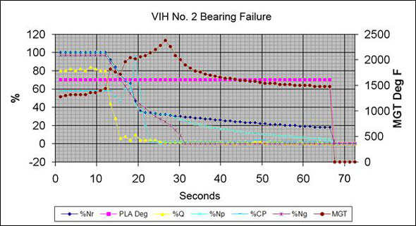
A portion of the inlet barrier filter located immediately forward of the engine's compressor inlet (normally the clean side of the filter) was bowed away from the engine and contaminated with debris, which is consistent with the momentary airflow reversal of a compressor stall. External inspection of the Rolls Royce M250-C47B engine did not show any obvious damage, but the compressor rotor (which includes the impeller) could not be rotated. The engine accessory gearbox chip detection system was tested and found functional. Data retrieved from the engine's electronic control unit (ECU) indicated that a Measured Gas Temperature (MGT) exceedence occurred almost coincidentally with an engine surge (compressor stall) and was followed immediately by a rapid decrease in engine torque, compressor and main rotor rpm (see Appendix A). There was no indication that the helicopter was being operated outside of its approved limits.
Maintenance
Records indicate the helicopter was serviced and maintained in accordance with existing directives. At the time of the accident, the engine and airframe had accumulated approximately 1254 hours total time since new, and there were no outstanding maintenance issues with either. The last routine inspection was completed about 8 hours prior to the accident. The maintenance history of the engine was unremarkable with the exception that the power turbine section was replaced about 437 hours prior to the accident because the No. 5 bearing generated metal which triggered a chip detection warning. The engine manufacturer indicated that the previous No. 5 bearing failure was unrelated to the power loss that occurred in this accident.
Engine Examination
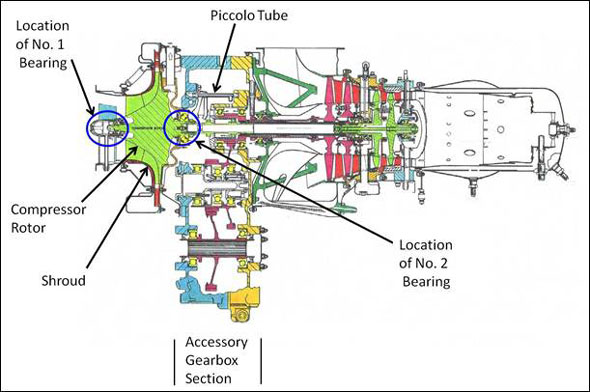
An examination of the engine (serial number CAE-848126) determined that the No. 2 bearing, (part number 23009670, serial number MP001190), which supports the aft end of the compressor, had failed (see Figure 1).
The compressor impeller vanes and the compressor shroud exhibited severe rubbing damage. The oil slinger, located between the No. 2 bearing and the compressor rear support, was cut circumferentially into 2 pieces. The No. 2 bearing support bore in the compressor rear support was not damaged, and the fit of the bearing in the bore was within limits. A substantial number of metal slivers and flakes were found on the magnetic portion of the upper and lower chip detectors in the accessory gearbox, and similar metallic debris were found loose inside the accessory gearbox.
The engine oil scavenge pump screen, the oil pressure pump filter, and the oil delivery (piccolo) tube were all free of contamination. No pre-accident defects were found with the lubrication system.
Compressor Design
The accident engine, an M250 Series IV FADEC (full authority digital engine control) engine is a development of the M250 Series IV non-FADEC engine. The single stage centrifugal compressor impeller in the FADEC engines is slightly larger and heavier than the compressor used in the non-FADEC engines. The No. 2 bearing that failed in the accident engine is used in both the FADEC and non-FADEC Series IV engines as well as in some other M250 Series engine models and has been for the last 20 years.
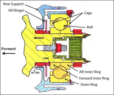
The forward end of the compressor rotor is positioned radially by the No. 1 bearing, a small roller bearing supported inside a housing on a thin film of oil. This oil film damped installation allows a small amount of radial movement of the bearing within the housing to help reduce vibration. The aft end of the rotor is supported by the No. 2 bearing, a large ball bearing designed to take combined radial and axial (thrust) loads as well as accommodate small amounts of angular misalignment. Angular misalignment in the No. 2 bearing can occur in part because slight radial movement is allowed in the No. 1 bearing. The angular misalignment in the No. 2 bearing results in moment loads.
The No. 2 bearing in the accident engine was manufactured for Rolls-Royce by Timken and is an on‑conditionFootnote 2 item. It consists of a circumferentially split inner ring (also referred to as a race), 10 balls, a ball separator (cage) and an outer ring (see Figure 2). Each component of the bearing is manufactured to a nominal dimension which incorporates a specified allowance above or below that dimension.
The difference between the extreme allowable dimensions of any one part is referred to as the dimensional tolerance. The combination of tolerances of all the parts in the assembled bearing is referred to as the bearing tolerance stack-up.
No. 2 Bearing Examination
The No. 2 bearing was taken to the TSB Laboratory for further inspection. Analysis determined that the bearing component alloys and hardness values were within the manufacturer's specified ranges; no pre-existing deficiencies were found with the No. 2 bearing materials. It was also determined that all of the metal particles found on the chip plugs and in the engine accessory gearbox matched the bearing and oil slinger material. There was no indication of a reduced oil flow to the No. 2 bearing.
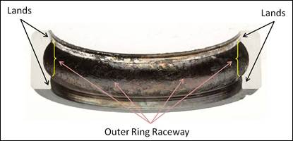
The outer ring racewayFootnote 3 was damaged by the balls skidding. It remained largely intact but was burnt and covered with coked oil which precluded examination of surface wear damage. The lands of the outer ring were extensively worn and heat-affected (see Photo 1).
The ball cage (also referred to as the ball separator) was distorted and the ball pockets bulged forward. The rails to each side of one ball pocket were fractured with at least one of the fractures being primarily fatigue induced. The outside surface of the cage was worn along the rails from contact with the lands of the outer ring.
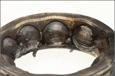
All 10 balls were similarly scored due to skidding (see Photo 2). Each ball had melted material (solidified metal droplets) at the edges of the skid area.
The raceways of the inner rings were burnt and covered with coked oil, precluding detailed examination of surface wear damage. Circumferential skidding marks were most severe on the aft inner ring raceway, and much of the material that formed the shoulder, that part of the raceway curvature nearest the land, was missing.
All of the No. 2 bearing components were thermally distressed. The greatest wear was found on the balls, the shoulder of the aft inner ring, and the lands of the outer ring where the cage contacted. The other engine components that were inspected, such as the No. 1, 6 and 7 bearings, were found to have been serviceable prior to the failure of the No. 2 bearing.
Bearing Design
According to T. A. HarrisFootnote 4:
For a bearing that supports a combined load, that is, radial and thrust loads and perhaps also a moment load, the operating contact angle is different at each azimuth angle. Therefore, a ball undergoes an axial excursion as it orbits the shaft. Unless this excursion is accommodated by providing sufficient axial clearance between the ball and the cage pocket, the cage will experience non uniform and possibly heavy loading in the axial direction. This can cause a complex motion of the cage. Such motion, together with the loading can lead to rapid destruction and seizure of the bearing.
Aircraft manoeuvres induce a gyroscopic moment reaction across the No. 1 and No. 2 bearings, thus, the compressor rotor acts like a gyroscope and resists changing its position when the aircraft yaws or pitches. This load on the No. 2 bearing increases ball excursions. If the excursions become too large, distress can occur that can lead to rapid destruction of the bearing. The No. 2 bearing is intended to tolerate aircraft manoeuvres up to about 200° per second, but the engine manufacturer concluded that a small number of bearings could be susceptible to large ball excursions during aircraft manoeuvres of a much lower rate depending on the bearing's as-assembled tolerance stack-up.
Large ball excursions can result in high ball-to-raceway contact stress, spallingFootnote 5 of the balls and raceways, and cyclical loading of the cage leading to fatigue cracking. If the cage cracks, the loss of hoop continuity allows it to expand radially, thus resulting in interference with the guide land and restraining the balls from rolling. If the excursions are large enough that the balls run completely off the raceway, scoring and grooving of the balls will occur. This results in ball skidding, overheating, metal generation and rapid bearing failure.
Bearings can fail for a variety of reasons, including material defects, improper installation, inadequate or contaminated lubrication, and abnormal loading. Most impending bearing failures, however, are preceded by progressive wear that generates metal debris for a period of time that is long enough to be detected either during routine maintenance (chip detector and oil filter inspections) or during operation (when the engine's magnetic chip detectors accumulate enough debris to illuminate a cockpit warning light). In either case, bearing wear is detected before damage is so extensive that it causes the engine to fail. In this accident, there were no indications of impending bearing failure, neither from routine maintenance inspections nor from cockpit chip lights prior to the engine power loss. The engine manufacturer has found that bearing failures resulting from cage fractures often do not provide much warning.
Prior to this accident, the engine manufacturer was aware of 4 similar No. 2 bearing failures involving Series IV FADEC engines but no similar No. 2 bearing failures in non-FADEC Series IV engines even though the non-FADEC engine fleet has accumulated roughly 4 times the total number of flight hours. Based on this information, it is apparent that the capability of the No. 2 bearings in the FADEC Series IV fleet has the potential to be exceeded compared to its capability in the non-FADEC Series IV fleet.
In each case, the rapid failure of the bearing resulted in the compressor moving forward and contacting the shroud that subsequently led to power loss without a chip light illumination. The No. 2 bearings from all 4 accidents displayed similar characteristics including severe damage to inner ring raceways, outer ring lands and the cage (including fatigue fractures in the cage rails). Rolls-Royce's investigations determined that the bearing failures were most likely the result of ball excursions exceeding the separator's pocket clearance, leading to fatigue crack initiation in the component. During this investigation, Rolls-Royce also found that interaction between a natural frequency of the separator and raceway defects, such as spalls, could contribute to fatigue of the separator rails.
The following TSB Laboratory report was completed:
- LP0197/2010 – Helicopter Bearing Examination (S/N: MP001190)
This report is available from the Transportation Safety Board of Canada upon request.
Analysis
When the No. 2 bearing failed, the compressor rotor moved forward until it contacted the shroud, causing the surge (compressor stall), engine spool down, and power loss. Because the loss of power occurred when the helicopter was on final approach to the landing area, at low airspeed and low height above uneven ground, it resulted in a hard landing.
The investigation determined that the helicopter had been serviced and maintained in accordance with existing directives and was being operated within its approved limits. The chip detection system was found to have been functional and the bearing had been correctly installed and adequately lubricated. The parts that comprised the bearing were manufactured of the alloys and hardnesses specified by the manufacturer, and no pre-existing deficiencies in those parts were found. As a result, this analysis will focus on compressor and bearing design.
Because the compressor rotor acts like a gyroscope, it resists changes in orientation during yaw and/or pitch manoeuvres. As the bearing supporting the forward end of the compressor rotor (the No. 1 bearing) is oil film damped, it allows some radial movement of the compressor rotor. This subjects the No. 2 bearing to large radial loads due to the compressor moment loads in addition to the normal thrust loads. These high loads are usually momentary but they can cause damage if they are frequent or have increased duration, particularly in bearings with tolerance stack-ups that make them prone to large ball excursions. The No. 2 bearing of this helicopter was manufactured with a tolerance stack-up that made it prone to large ball excursions at manoeuvre rates less than the design maneouvre envelope. The ball excursions led to rapid failure of the No. 2 bearing and subsequent engine failure.
The bearing failure was unusual in that it was very rapid, and it was not preceded by a chip detection warning. It also damaged the bearing components, in particular the cage and the aft inner race, in a way not typical of other, more common, bearing failures.
Findings as to Causes and Contributing Factors
- The tolerance stack-up of the No. 2 bearing made it prone to large ball excursions at manoeuvre rates less than the design maneouvre envelope.
- The ball excursions led to separator fatigue followed by rapid failure of the No. 2 bearing and subsequent engine failure.
- The time of the engine power loss, at low airspeed and low height above the ground, contributed to the hard landing.
Finding as to Risk
- This mode of bearing failure is not preceded by a chip light indication.
Safety Action Taken
On 11 April 2011 Rolls-Royce issued a Commercial Engine Bulletin (CEB) which included CEBs 72-3285, 72-5058 and 72-6067. The bulletins require that No. 2 bearings with part number 23009670, 6898606 or 6893002 be replaced with bearing part number M250-10354, which incorporates several design changes that address the various items identified as part of the investigation, resulting in an improved design capable of meeting manoeuvre requirements across its allowable manufacturing and installation variation. The CEB requires that the No. 2 bearing be replaced the next time the engine, module, or component is sent to an authorized repair/overhaul facility for any reason.
Transport Canada and the Federal Aviation Administration concluded that the probability of another similar No. 2 bearing failure was too low to warrant safety action beyond that recommended in Rolls-Royce's CEBs.
This report concludes the Transportaion Safety Board's investigation into this occurrence. Consequently, the Board authorized the release of this report on .
Appendices
Appendix A – Electronic Control Unit (ECU) Graph
Legend:
%Nr – percentage rotor rpm
PLA Deg – power lever angle (throttle position)
%Q – percentage torque
%Np – percentage power turbine rpm
%CP – percentage collective control position
%Ng – percentage gas turbine rpm
MGT – measured gas temperature (°F)
