Tail Rotor Driveshaft Fracture
Black Tusk Helicopters
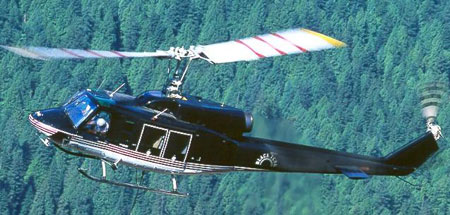
Bell 214B1 (Helicopter) C-FWQU
Ramsay Arm, British Columbia
The Transportation Safety Board of Canada (TSB) investigated this occurrence for the purpose of advancing transportation safety. It is not the function of the Board to assign fault or determine civil or criminal liability. This report is not created for use in the context of legal, disciplinary or other proceedings. See Ownership and use of content. Masculine pronouns and position titles may be used to signify all genders to comply with the Canadian Transportation Accident Investigation and Safety Board Act (S.C. 1989, c. 3).
Summary
The Bell 214B1 helicopter (registration C-FWQU, serial number 28029), operated by Black Tusk Helicopters, was carrying out heli-logging operations in Ramsay Arm, British Columbia. At about 0800 Pacific daylight time, the helicopter was in a 200-foot hover and starting to pick up the 11th load when the two pilots noted a loud growling sound from within the helicopter. Immediately, the flying pilot discontinued the lift and released the load from the longline hook. He then flew the helicopter back towards the nearby service area to have the noise investigated. About 20 seconds later, just as the helicopter entered a high hover above the service landing site, the growling noise stopped, the low oil pressure warning lights for the two tail rotor gearboxes illuminated, and the helicopter rotated quickly to the right. The pilot was unable to stop the rotation using the tail rotor control pedals and the helicopter made two or three 360-degree turns to the right. The pilot rolled off the throttle on the collective stick and attempted to land in trees adjacent to the service area. The helicopter descended upright and struck several trees before landing hard on the uneven terrain. The flying pilot, seated in the left hand seat, was seriously injured and the co-pilot received minor injuries. The helicopter was substantially damaged during the landing and there was no fire. The emergency locator transmitter activated at impact and survived the crash.
Factual information
Pilots
Records indicate that the pilots were certificated and qualified for the flight in accordance with existing regulations. There was no deviation from Transport Canada (TC) regulations respecting flight and duty time limits; neither had been engaged recently in particularly arduous operational activities.
The pilot-in-command was an experienced and qualified Bell 214B1 captain, with prior vertical reference external load operations (VREL)Footnote 1 experience. He had worked for the operator in the heli-logging arena for several years. He had about 17 000 hours of total flying experience, with about 4000 hours on type. At the time of the accident, he was the company chief pilot.
The co-pilot was new to heli-logging and had worked for the operator for one week. As the non-flying pilot, his functions were to record all operational times, load weights, and engine performance, to act as a safety pilot, and to accumulate flight experience.
The pilots did not deviate from contingency procedures in the TC-approved rotorcraft flight manual (RFM).
Weather
Weather conditions were suitable for flight in accordance with visual flight rules (VFR) and were not a factor in the accident.
Helicopter
The accident helicopter, C-FWQU, was manufactured in 1978. Black Tusk Helicopters (BTH) imported it into Canada in 1995 when it had accumulated 7312 hours of service. At the time of the accident, it had accumulated 17 537 hours of service. Records indicate that the helicopter was certificated, equipped, and maintained in accordance with existing regulations and approved procedures.
A review of recent logging load records showed that the weight of the helicopter had not exceeded certificated external weight limits. Post-accident calculations showed that the weight of the helicopter at the time of the accident was about 9200 pounds; the certificated maximum permitted external weight is 16 000 pounds.
Post-Crash Examination
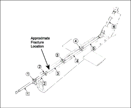
An examination of the wreckage at the site revealed that the No. 3 shaft in the tail rotor driveshaft assembly (TRDS) had fractured 18 inches behind the forward coupling, causing loss of drive to the tail rotor. This resulted in the gearbox warning lights illuminating, the rapid rotation to the right, and the loss of directional control.
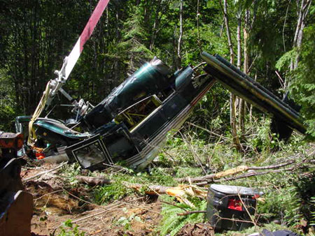
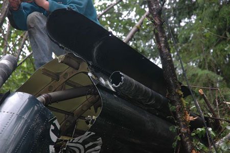
Scoring and abrasion damage had occurred to several sections of the top of the tail boom beneath the TRDS. The tail boom had broken in two parts at impact, with the break slightly forward of the broken shaft. (See Photo 1 and Photo 2)
The Growl
The low-frequency growling sound was estimated to be at about 90 Hertz (Hz). At 100 per cent main rotor rpm, the TRDS turns at 4988 rpm, which equates to a frequency of 83 Hz. The frequency of the sound heard by the pilots was consistent with the rotating TRDS striking the tail boom. No unusual vibration in the airframe or flight controls was felt. The noise stopped when the shaft separated.
Certification
The Bell 214 helicopter was first introduced in 1970 as an evolution of the military UH-1 and model 309 King Cobra gunship helicopters. The first Bell 214A production model was manufactured in April 1975 by Bell Helicopter Textron, Inc. (BHTI). The commercial derivative, the Bell 214B "Big Lifter", which provided better lift capability than any single-engine commercial helicopter in production at that time, was certificated by the United States (US) Federal Aviation Administration (FAA) in January 1976 and had a limited production of 70 helicopters. It was replaced by the Bell 214B1 model, which was re-certificated to a lower maximum internal gross weight of 12 500 pounds.
The Bell 214ST belongs to the same family of helicopters, but it is substantially larger and is powered by two engines.
Bell 214B1 Tail Boom
The tail boom on the accident helicopter was manufactured by BHTI as part number 214-030-003-7. The BHTI structural repair manual for the Bell 214B1 records that the tail boom skin is made from 2024-T3 aluminium alloy sheet. A review of historical maintenance logs revealed no record of tail boom replacement or overhaul.
Tail Boom Damage
The tail boom was attached normally when the helicopter struck the terrain, and the forces of impact fractured the tail boom about 36 inches from the forward end (see Photo 1). The fracture surfaces are all due to overload and consistent with heavy downward tail boom contact with the ground.
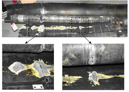
The top of the tail boom was severely damaged by the No. 3 shaft of the TRDS. Rotational damage that could have only occurred before the shaft broke is seen in several places on the tail boom skin directly below the TRDS, particularly in the areas where frame bulkheads and stiffeners were located. The driveshaft fractured over a bulkhead (see Photo 3). Damage also occurred when the fractured ends of the shaft whipped around inside the TRDS cover. This confirms that damage occurred both before and after the shaft fractured. The flailing of the broken shaft at the main transmission end created sympathetic misalignment with the No. 2 (short) shaft and caused scoring and perforation of the tail boom and fuselage top deck skins below it.
Also noted on top of the tail boom were several distinct areas of paint degradation that appeared to be the result of exposure to high heat. Research of the engine exhaust efflux pattern showed that the hot exhaust gases impinge on the tail boom in the areas noted.
Bell 214 Tail Boom Modification History
In June 1977, BHTI issued Alert Service Bulletin (ASB) 214-77-8 for the Bell 214B and B1 helicopters. It required the daily inspection of the vertical fin forward spar area for cracks that had previously caused an in-flight failure of the tail boom vertical fin during heli-logging operations.
In January 1978, BHTI issued ASB 214-78-1 for the Bell 214B and B1 helicopters mandating the replacement of the aluminium spar cap on the tail fin with a stainless steel cap. This ASB was the basis for the FAA Airworthiness Directive (AD) 78-08-08 on the same issue. In developing the 1978 ASB action, BHTI carried out a flight strain survey that determined that flight loads during heavy lift operations increased fatigue loads and lowered the fatigue life of the spar cap angle. The TSB was not given any information by BHTI about the flight strain survey (see the section below titled "BHTI Policy of Non-disclosure of Vital Information"). As a consequence, the TSB did not have access to information concerning the research and findings that led to the tail boom modifications, specifically those conducted by BHTI on thermal damage and in-flight loads on the tail boom during high-power hovering operations. BHTI chose not to disclose this information under the auspices of the International Traffic in Arms Regulations of the United States of America.
In November 1978, BHTI issued Technical Bulletin 214-78-18 for the Bell 214B and B1 helicopters that dealt with the reinforcement and repair of the tail boom, precipitated by in-service cracking of certain tail boom bulkheads. The addition of doublers and brackets provided a repair method for bulkheads that had already cracked. The accident tail boom had not been modified as described in the technical bulletin, nor was it required to have been.
The issue of thermal buckling and structural weakness of the tail boom within the Bell 214 family is known to BHTI. In October 1992, BHTI issued ASB 214ST-92-58 for a similar helicopter model, the twin-engine Bell 214ST, regarding modification to the tail boom to prevent thermal buckling of the top skin. Buckling caused contact between the tail rotor driveshaft and the tail boom, leading to driveshaft imbalance and vibration. It was likely that with such imbalance, the driveshaft would further have been damaged, rapidly leading to driveshaft failure and loss of directional control.
This extensive modification to the Bell 214ST tail boom included replacing specific support structures and adding doublers to the top skins on the tail boom. The areas on the tail boom affected by this modification lay beneath the exhaust efflux. The tail boom on the Bell 214ST is not identical to the Bell 214B/B1, yet it is the same dimensionally and remarkably similar in construction with the Bell 214ST tail boom designed to accept greater loads.
Another indication of the high loads present in the Bell 214 model tail boom was provided in the issue of FAA AD 96-07-12, dated 10 May 1996 (again for the Bell 214ST). In summary, this AD required repetitive inspections for tail boom cracks until modifications of the tail boom were accomplished. The modifications were designed to prevent:
- cracks in the tail boom assembly;
- structural failure of the tail boom; and
- subsequent loss of control of the helicopter.
The AD also included installing stiffeners and doublers in the tail boom, and replacing the access door frame with a stronger one.
Bell UH-1 Tail Boom Structural Problems
In 2004, the US military identified tail boom structural problems resulting from high heat in the tail booms of helicopter models similar to the civilian Bell 214B and implemented a regime of operational and structural changes to address the problemsFootnote 2. Specifically, tail boom structural problems were encountered during the developmental testing of the twin-engine Bell AH-1Z and UH-1Y helicopters in early 2004. Program flight-testing was paused because of decreased structural strength in tail boom components caused by increased engine exhaust temperatures and higher loads and torques imparted on the tail boom.
The NTIAC article states, in part:
Higher aircraft gross weight for the Y/Z, coupled with an upgraded transmission, allows the engines to operate at optimal performance, creating more power and resulting in increased exhaust gas temperatures, loads, and torque. The higher temperatures of the exhaust gases hitting the tail boom structure caused greater-than-expected weakening of the metal, known as annealing.
Following an intensive review of data and engineering review, the aircraft have been returned to a flight status with a reduced gross weight envelope and are undergoing interim modification of the tail booms that will restore a full envelope. This interim modification involves adding skin and structure "doublers" to the tail boom that will return it to original design specifications for heat tolerance.
An airframe upgrade was then developed by BHTI that addressed the root cause of the problem by turning the exhaust gases away from the tail boom, thereby decreasing the effect of exhaust gas heating. No such modification was available for the civilian Bell 214B helicopter.
BHTI has been aware of the tail boom structural issues affecting the Bell 214B/B1 helicopter type since 1978. At the time of this report, the worldwide fleet of these helicopters numbered about 30 aircraft, with 4 of them being in Canada. The aircraft in Canada are believed to be the only units assigned to heli-logging service. BHTI has no plans to re-design or produce any new exhaust or tail boom components.
Examination of Broken Tail Boom
As a result of the visible indications suggesting heat damage to the tail boom upper skin, four large coupons of skin were cut from the tail boom - two from an area that was suspected to have been affected by heat, and two from an area that appeared unaffected. The coupons were examined and analysed by the TSB Engineering Laboratory and the results are contained in report LP 067/2007.
The coupons showed significant changes; the room temperature tensile strength was only 83 per cent of the standard value and the conductivity had been altered. These results are consistent with prolonged exposure to elevated temperature.
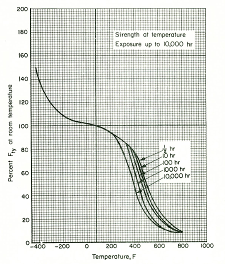
The 2024 series of aluminium alloy has material properties that tend to degrade as a result of exposure to elevated temperatures. For example, at elevated temperatures these alloys have reduced yield strength as shown in Figure 1. Furthermore, the time exposed to higher temperatures has a cumulative effect, reducing yield strength even further. In addition to reduced yield strength, exposure to elevated temperature reduces the modulus of elasticity, a measure of stiffness. For example, in the range 400 to 499°F (204 to 259°C), the temperatures measured during the temperature survey, the modulus of elasticity drops to about 81 per cent of its room temperature value.
At the time of the accident, C-FWQU had accumulated over 17 500 hours of service, likely with the accident tail boom as original, but, in any event, the accident tail boom certainly had accumulated at least 10 200 hours since importation into Canada in 1995. It is noteworthy that the accident tail boom demonstrated reduced ultimate tensile strength in the same top skin areas that were the subject of the several tail boom modifications in various models of the Bell 214 family of aircraft.
The civilian and military tail booms could be similarly affected by the extremes of high exhaust heat and main rotor torque, irrespective of single or twin-engine configuration. The structural failures that led to the issue of the tail boom-related ASB's and the US military tail boom-related design changes suggest that the design of the tail boom did not adequately protect against high temperatures from the engine exhaust, in particular during high-power situations such as during vertical reference hovering. The TSB had no access to engineering information concerning the tail boom structure.
TSB Field Temperature Trials - Tail Boom
As a result of the TSB's preliminary findings of the tail boom skin weakness, a temperature monitoring trial was conducted. Temperature-sensing decals were applied to identical locations on the tail booms of three Bell 214B1 helicopters carrying out vertical reference operations in British Columbia (BC) and recording of the decals was carried out by field maintenance personnel. The results of the trial showed that the tail boom was constantly exposed to exhaust gas temperatures between 204 and 259°C (400-499°F) in the areas that coincided with paint destruction by heat seen on the accident tail boom. Photo 4 shows the engine exhaust gas path flowing over the tail boom.
Bell 214B1 Tail Rotor Driveshaft Assembly (TRDS)
On this Bell 214B1 helicopter, the TRDS comprises six separate driveshaft segments, of which five are identical. The No. 2 shaft segment is shorter than the rest. The remaining five shafts are interchangeableFootnote 3 and are normally identified by part number 214-040-622-005 and a unique serial number etched or stamped on each component. The shafts are normally referred to as No. 1 at the main transmission through to No. 6 in the tail boom pylon (see Figure 2). The shafts are manufactured by BHTI from aluminium tube stock, with attachment flanges riveted onto each end.
TSB laboratory analysis determined that the alloy was most probably 2024-T3 or -T4. The shaft segments are interconnected at the flanges using Thomas couplings supported by hanger bearing assemblies mounted on top of the tail boom. The required dynamic balancing of each shaft is done only by BHTI, either at the time of manufacture or repair. If the shaft is re-balanced or repaired, the serial number remains unchanged.
TRDS Condition Monitoring
As allowed by the manufacturer and approved by TC, the tail rotor driveshaft segments on C-FWQU were condition-monitored (also referred to as on-condition). This means that the components had no finite life in service; their serviceability was based on their present condition. On-going assessments were performed by qualified aircraft maintenance engineers (AMEs) employed by the operator at least twice daily during heli-logging operations. Their assessment consisted of a visual examination of the shaft, looking for scratches or dents that exceeded the small damage tolerances established by BHTI and in accordance with the instructions contained in BHT-214B-CR&O-1, section 66-116D, Inspection - Tail Rotor Driveshaft, and section 66-116E, Repair - Tail Rotor Driveshaft.
Because these driveshafts were condition-monitored items, the traditional Canadian component history record card (CHR) was not raised for them, nor was a CHR required by Canadian regulations. As a result, their service history was not specifically recorded. Anecdotal knowledge and component serviceability tags provided partial traceability of any particular shaft.
The 214-040-622-005 driveshaft is a condition-monitored item when used on civilian Bell 214B, 214B1, and 214ST helicopters. However, in its military application, the shaft has a finite life. Therefore, when BHTI provides a new shaft to civilian customers, it automatically includes a Bell component card as normal practice. BHTI advises civilian customers that, while the component card is not a requirement for time tracking, it might be a useful tool to track maintenance on the shaft, particularly if a re-balance is required.
TRDS No. 3 Shaft History
The fractured TRDS segment in this accident is the No. 3 shaft, positioned at the beginning of the tail boom section. It was identified by serial number A-643A from original manufacture. The history of this shaft is available only from when C-FWQU was imported into Canada in 1995, when the helicopter had accumulated 7312 hours. A review of the historical maintenance logs found no record indicating that the shaft had been replaced before 1995. Shaft A-643A remained in service in C-FWQU for another 2670 hours, when it was removed in October 1997 for a suspected out-of-balance condition.
In January 1998, BTH sent the shaft to the BHTI facility in Texas, US, and asked BHTI to inspect it, and to rebalance it if possible. In July 1998, BHTI conducted a preliminary engineering inspection and found no imbalance, but decided to conduct a secondary inspection. This inspection identified two separate issues: a gouge on the shoulder of one of the couplings and surface pitting, which was described as "rough to touch." There is no record of any assessment or repair in accordance with the instructions of the BHTI Component Repair and Overhaul manual (CR&O), sections 66-116D or 66-116E. As a result, BHTI declared the shaft as scrap and stated as such in an e-mail to BTH. The shaft was returned to the company in August 1998.
Shaft A-643A remained in quarantine at BTH until August 2002 when it was sent to Transwest Helicopters (TWH) of Chilliwack, BC, along with an identical driveshaft segment (A336). At that time, TWH was a BHTI-approved customer support facility and also operated a fleet of three Bell 214B1 helicopters. TWH is an authorized and licenced maintenance, repair, and overhaul (MRO) facility for the Bell 214 and has the Honeywell-correlated test cell for the Lycoming T55-08D engine, with an exclusive license to manufacture the engine. TWH independently examined shaft A-643A, carried out the approved inspection and repair instructions contained in the CR&O manual, sections 66-116D and 66-116E, and assessed it as serviceable. TWH then installed it in one of their helicopters, which then flew about 500 hours in seven months without event.
The shaft was removed from the TWH helicopter in March 2003 and was returned to BTH as a serviceable component. The TWH maintenance release tag recorded the serial number as "A643A." A maintenance release tag signifies that the specific component is serviceable in accordance with applicable airworthiness standards.
In May 2003, BTH installed the shaft in C-FWQU, where it remained until the accident, accumulating a further 3300 hours in 45 months. At this last installation, the shaft serial number was incorrectly recorded on the BTH maintenance release tag as "A6431A"; the original number engraved on the shaft was unchanged.
An examination of the associated maintenance release tags revealed that a simple transcription error had occurred because of individual handwriting characteristics. Although the recorded serial number was inadvertently changed, in this case there was no loss of continuity of the shaft's record of service in Canada. In summary, the total hours in service of this particular driveshaft was at least 6500 hours.
TRDS Inspection Procedures
Sections 66-116D and 66-116E of the BHTI CR&O for the Bell 214B helicopter prescribe the actions required to inspect the TRDS shafts, as well as listing the acceptable damage tolerances. In part, these two sections identify two surface regions - A and B - which have differing maximum depths for acceptable nicks, scratches, and dents. In summary, the instructions prescribe the steps to inspect, assess, and repair the shafts, including the process to remove corrosion and pitting and to repair any damage to the anodized finish. Furthermore, other BHTI reference publications, such as CSSD-PSE-87-001 Chapter 15-3(3)(a) - Surface Corrosion and Pitting, and BHT-ALL-SPM Chapter 3-8 - Corrosion Removal - Aluminium Parts, pertain to the assessment of corrosion.
As a BHTI-approved customer support facility, TWH possessed the equipment and expertise to examine and dynamically test tail rotor driveshaft segments for imbalance. TWH was not approved to balance tail rotor driveshafts, nor was any evidence found that it had done so. In practice, it was not unusual for TWH to identify minor balance characteristics for particular driveshaft segments, index them accordingly, and successfully eliminate TRDS and tail boom vibrations by systematic alignment.
TRDS No. 3 Shaft Previous Damage
During the investigation, the TSB learned of another similar incident in 2001 involving a different No. 3 tail rotor driveshaft segment on another Canadian Bell 214B1 helicopter at Nakusp, BC. On this occasion, the pilot reported a loud growling sound during a heli-logging pick-up; he aborted the mission and returned to the service landing without further event. An inspection of the still-intact tail rotor driveshaft segment revealed rotational scoring damage in about the same location as the accident shaft, with abrasion damage to the top of the tail boom that created a two-inch hole. Subsequently, the driveshaft was replaced, the tail boom repaired, and the helicopter was returned to service. No further investigation of this incident was pursued and the cause was unknown.
TSB Examination of TRDS
The fractured section of TRDS was visibly discoloured compared to other sections located further away from the engine exhaust. Test coupons were cut from the fractured shaft and from a comparison shaft with no visible indications of heat damage. The coupons were examined and analysed by the TSB Engineering Laboratory and the results are contained in report LP 067/2007. Only a small change in conductivity and small reductions in yield and ultimate tensile strength were found, significantly less than the tail boom skin heat damage.
TSB Field Temperature Trials - TRDS
Although the TSB's temperature monitoring trial showed that the tail boom was constantly exposed to exhaust gas temperatures between 204 and 259°C (400-499°F), no such determination was made regarding the tail rotor driveshaft segments. Because the TRDS was vulnerable to imbalance, temperature decals were not applied to the segments and accordingly no measure of the typical operating temperatures of the individual shafts was obtained.
The series of decals on the tail boom showed that the temperature of the top skin inside the TRDS cover (as indicated by the inner sets of decals next to the shaft) was less than the skin temperature outside the cover. The laboratory tests of the TRDS material did suggest that the driveshaft appeared less heat-affected than the tail boom. Nevertheless, the TRDS was still being exposed to elevated temperatures from the engine exhaust, even though it was probably not exposed to temperatures as high as the tail boom skins. Such exposure may have contributed to the driveshaft segment fracture. Engineering information pertaining to the tail rotor driveshafts was not provided by BHTI.
Vertical Reference External Load Operations
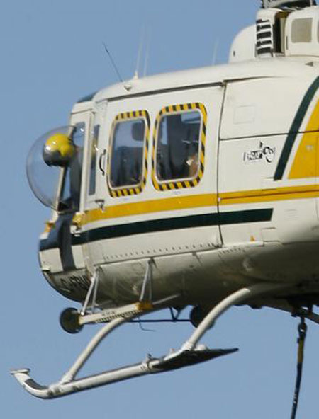
The term vertical reference external load (VREL) operations is used to generally describe the manoeuvring of a helicopter, often with a longline and hook attached, by the flying pilot using the load (or hook) as the primary hover reference point, in contrast to conventional hovering techniques that use multiple reference points and peripheral visual cues. In most helicopters, such a flying technique characteristically requires the pilot to lean out the cockpit window or door; these are often fitted with a "bubble" window to protect the pilot from wind and noise (see Photo 5).
On helicopters used in VREL flying, such as the Bell 214 and the Sikorsky S-61, cockpit dimensions and fuselage width require the flying pilot to lean markedly to one side to be able to clearly see the longline and load suspended below the helicopter. Because it is physically impossible for a pilot to achieve such a body position when wearing the shoulder harness portion of the seat restraints, it is a widespread practice for the pilot manoeuvring the helicopter to use the lap belt portion only. In helicopters dedicated to vertical reference flying, it is common for the loose shoulder straps to be semi-permanently stowed behind the seat back to prevent them from interfering with the pilot's movements or controls.
Structural Stresses - VREL Operations
In general, the vertical reference flying technique used in heavy-lift helicopter operations involves rapid and sometimes extreme flight control inputs, with the helicopter constantly experiencing attitudes and rates of attitude change greater than during conventional route flying. Furthermore, the demands on the engine/transmission system cycles - from low to high power several times during the load pick-up and drop-off - imposes high stress and cycle counts on critical components, notably the tail rotor drive train and tail boom structure. The Bell 214 helicopter was marketed as the "Heavy Lifter" and throughout the helicopter industry it has achieved a reputation of being suited for such demanding operations. It was also well-known that the Bell 214 tail boom twisted and bent during heavy lift operations, and the tail boom skins wrinkled and buckled noticeably under high tail rotor demand. The tail boom appeared to be an ongoing vulnerability for the model, with the issue of many ADs, ASBs, and modifications pertaining to the identification and repair of tail boom flexure and cracking brought about by designed in-service use.
Crashworthiness and Survivability
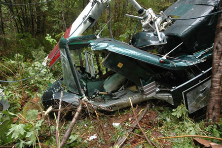
Impact forces were severe, the level of airframe destruction was high, and the occupiable volume for the rear cabin was significantly reduced (see Photo 6).
The cockpit area was also crushed, with the left side sustaining far more damage than the right side. It is this level of damage that caused the pilot in the left seat to receive serious injuries and the co-pilot to receive minor injuries.
The pilot-in-command remained secured in the left seat during the impact and was injured by the disruption and break-up of the cockpit around him. He was wearing a flight helmet and the lap belt portion of his seat restraint, but not the available shoulder harness; the shoulder straps had been left loose behind the seat back. The pilot did not use the shoulder harness because it prevented him from leaning out to view the external sling load. The co-pilot was secured in his seat with the full lap belt and shoulder harness restraint fastened; he was not wearing a helmet.
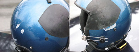
The impact damage to the flying pilot's helmet shows that the helmet prevented more serious head injuries (see Photo 7). Had he been able to wear the available shoulder harness, the injuries he did receive would likely have been less severe.
The Canadian helicopter industry acknowledges that the use of flight helmets has prevented serious head injury in many terrain collision accidents, and that the safety benefits far outweigh any inconvenience and discomfort. Many Canadian operators actively encourage or even require their pilots to wear flight helmets in most operational conditions, including during aerial work and passenger transport operations. The Canadian Coast Guard mandates and provides flight helmets for all of its helicopter flight crews.
Pilot Shoulder Harnesses
Conventional seat restraints fitted in most helicopters are not well-suited to VREL operations. Slinging external loads using vertical reference flying techniques is common in helicopter operations worldwide, with a high proportion of operations using this technique in Canada. Most helicopters are not designed to accommodate such flying techniques, and certification for external load operation does not take them into account.
In a 1997 accident involving a Sikorsky S-61 near Stave Lake, BC (TSB report A97P0094), although the impact forces were survivable, the co-pilot perished as a result of being crushed by the helicopter as it rolled over. The co-pilot was wearing the lap belt portion of his seat restraint, while the shoulder harness was found free, and it was determined that he would have been better restrained and his injuries lessened by using the available shoulder harness.
An analysis of helicopter crash dynamics by ColtmanFootnote 4 shows that, of those occupants involved in helicopter crashes, 34 per cent of those wearing just the lap belt portion sustained severe injuries, compared with only 9 per cent of those wearing the full seat restraint.
Accident investigation and research carried out by the TSB has consistently shown that the use of the shoulder harness portion of the seat restraint system was effective in reducing or preventing injury during moderate impact forces. It was likely that the use of the shoulder harness in this Bell 214B1 accident would have lessened the pilot's injuries, and the general situation where vertical reference pilots eliminate the shoulder harness is cause for concern. Given that vertical reference flying necessitates upper body freedom of movement, the universal dismissal of the shoulder harness, in its present configuration, is almost inevitable.
Furthermore, it is likely that the regular non-use of the shoulder harness diminishes a pilot's awareness of its safety advantages and at the same time reinforces a less-than-ideal safety practice.
Previous Safety Action Taken
In 2001, the TSB sent Safety Advisory 625-A010006 to TC, which advised that, although the seats in the cockpit of helicopters were equipped with four-point seat restraints, many pilots used only the lap belt portion. Furthermore, those pilots fastened the lap belt loosely when carrying out vertical reference operations. In response to the safety advisory letter, TC stated that it was the aviation industry's responsibility to comply with the regulations and, if warranted, to apply for approval of a configuration to meet its operational needs.
In 2005, the TSB sent a Safety Information Letter to TC outlining the circumstances of another near-fatal helicopter longline accident near Bella Bella, BC (TSB reference: 825-A05P0103). The letter stated that, despite the Canadian Aviation Regulations (CARs) and the previous Safety Advisory to TC in 2001, helicopter slinging operations in Canada continue without the upper body restraints being utilised.
In response to this safety letter, TC provided the following comments:
- If the upper body restraint equipment is used properly and in accordance with the CARs, they will provide the protection intended by those requirements.
- It is the operations being conducted when these accidents occurred that led the pilots to loosen and/or remove elements of their restraint system. The existing CARs (Section 605.27(3)) require at least one pilot to have the safety belt, which, as per the definition in Section 101.01 of the CARs, includes the shoulder harness fastened during flight time.
- If an operator discovers that installed equipment, shoulder harness in this case, is unsuitable for "Vertical Reference Helicopter Sling Operations," then Transport Canada has a well-established process in place for assessing and approving supplemental aircraft equipment.
- It is the responsibility of the industry to comply with the regulations and, if warranted, to apply for an approval of a configuration to meet the industry's operational needs. Transport Canada continues to welcome air operator and manufacturer initiatives to promote safe helicopter external load operations.
- Notwithstanding the current regulations and industry initiatives undertaken to date, Transport Canada has initiated the process to conduct research and development on the issue. A proposal has been submitted to the Civil Aviation Research and Development Committee to study crew restraint in VREL operations. The objective is to develop a new restraint system and produce a safety education and promotion product on VREL operations.
In April 2006, TC began a research and development project on VREL restraint systems, with the intent of providing the results to the industry so that a new system could be certificated, manufactured, and made available to Canadian operators.
In May 2006, TC learned that Alpine Aerotech Ltd. had been developing a VREL restraint system called the Vertical Reference Seat Kit (VRSK) that allows a regular helicopter pilot seat to be used in vertical reference operations and still maintain the safety benefits of the full seat restraint system. In December 2006, following certification evaluation, TC issued Supplemental Type Certificate (STC) SH06-31 to Alpine Aerotech. The VRSK had been approved for the Bell 205 series, the Bell 212, and the Bell 214B/B1.
Because the certification of the VRSK addressed the safety initiative that TC was originally targeting, the TC project was postponed and held open for possible use for other helicopter models. TC will consider reactivating this project should the industry indicate assistance is required for other helicopter types.
BHTI Policy of non-disclosure of Vital Information
In November 2007, during the course of this investigation, BHTI informed the TSB that it would not provide any engineering data and test results concerning the Bell 214B/B1 because it maintained that the release of data concerning this helicopter model was restricted under the International Traffic in Arms Regulations (ITARs) imposed by the US Department of State (DOS). For further information, see the US Code of Federal Regulations (CFR) Article 22. BHTI also did not provide access to non-ITARs proprietary information. Therefore, the TSB did not have access to potentially vital information for the accident investigation and for validating potential safety deficiencies.
United States ITARs Provisions
The provisions of the ITARs are formulated by the US DOS and provide control over the export and import of defence articles and services. The rules also provide a mechanism for the release of certain ITARs-related information, subject to an application to, and the approval from, the US DOS.
The TSB approached the US DOS in Washington, DC, to ascertain the likelihood of release of selected data regarding the Bell 214B1 helicopter involved in this accident. It was clear from these discussions that although the Bell 214B1 was affected by the provisions of the ITARs, the information that the TSB was seeking in reference to the accident investigation was releasable. Any approval for release of information would be subject to a formal request from BHTI as the original manufacturer. BHTI chose not to seek approval for the release of the requested information.
Analysis
Flight crew actions did not contribute to the accident circumstances. The dismissal of the shoulder harness, which is a common practice of pilots engaged in this type of operation, remains a concern. This investigation focused on the design and maintenance issues surrounding the tail boom and tail rotor driveshafts.
Based on the behaviour of the helicopter in flight, the damage to the airframe and tail rotor driveshaft, and the conditions reported by the pilots, it was determined that the driveshaft fractured while the helicopter was entering the hover at the service landing. This led to the low oil pressure warning lights, the rapid rotation to the right, and the loss of directional control.
TRDS Component Tracking
The lack of accurate tracking of the fractured TRDS shaft did not allow for accurate monitoring of its service history. However, the TRDS shafts are condition-monitored parts and subject to ongoing assessment by qualified AME's, which is an accepted industry practice.
Despite the initial assessment by BHTI that the failed shaft was unserviceable because of pitting, TWH examined and re-assessed it as airworthy in accordance with the instructions contained in the BHTI-approved CR&O manual, sections 66-116D and 66-116E, and subsequently operated it without event. That the shaft continued to operate for an additional 4 years and 3300 hours supports the TWH assessment that it was serviceable at that time. It is noteworthy that during this period, the driveshaft was inspected by qualified AME's in the field at least twice each flying day.
Tail Boom Structural Weakness - Effect of Extreme Temperature
The TSB's temperature monitoring trial showed that the tail boom was constantly exposed to exhaust gas temperatures between 204 and 259°C (400-499°F). Metallurgy research shows that exposure to such elevated temperatures over time affects the metallurgical properties of the metal skins, causing the metal to lose strength and stiffness. The accident tail boom had accumulated at least 10 000 total hours in service, but most likely it had accumulated 17 500 hours. Exposure to this level of elevated temperature over such time would result in the elevated-temperature yield strength being only 30 to 40 per cent of its room temperature standard value. This represents a significant reduction in the strength of the tail boom structure.
Previous modifications to correct structural thermal buckling and TRDS interference in similar tail booms were issued by BHTI. There were also structural changes to similar US military helicopters. This suggests that there is an inherent design weakness with the tail boom in the Bell 214B/B1 helicopter models. It is likely that the civilian and military tail boom design and construction are sufficiently similar that fatigue and heat stress known to affect the military helicopter models is also present in the civilian models, irrespective of single or twin-engine configuration.
Tail Boom Distortion - Effect of Repetitive Heavy Lifting
Repetitive heavy-lift operations create high-cycle limit loads on the helicopter structure and components. Helicopters engaged in heli-logging invariably operate in the highest weight, engine power, and transmission torque combinations and, as a result, cause high anti-torque forces to be transmitted to the tail boom assembly. It is characteristic of the Bell 214 tail boom structure to visibly exhibit bending, twisting, and buckling under these high torque/power situations. For the higher gross weight model, the Bell 214ST, such buckling had led to failure and was evident despite the lower frequency of high power/torque levels. As well, the military models similar to the Bell 214B/B1 encountered similar structural problems with tail boom distortion. As a result of twisting and bending during heavy-lift operations, the Bell 214 tail boom skins wrinkle and buckle noticeably under high tail rotor demand, potentially leading to tail boom distortion and interference with the TRDS.
Progressive TRDS Weakness
The TSB's temperature monitoring trial did not permit any determination regarding the operating temperature extremes of the TRDS. However, the balance of the physical and metallurgical evidence indicates that the TRDS segment below the exhaust efflux was constantly subjected to high temperatures, sufficiently elevated to degrade the yield strength of the metal over time. In turn, such degradation could have led to progressive susceptibility to reduced rigidity and vibration, and contributed to eventual fracture.
Tail Boom Distortion and Fracture Scenario
The No. 3 segment of the TRDS came into contact with the top deck area of the tail boom during flight, leading to the rapid weakening of the TRDS and its ultimate fracture. The growling noise heard by the pilots at the beginning of the accident sequence was the result of the TRDS segment striking the top skin of the tail boom inside the TRDS cover. In light of earlier structural problems with the tail boom on several similar Bell 214 model helicopters, the scenario to best explain how the TRDS struck the tail boom on C-FWQU is discussed in the following paragraphs.
To cause the shaft to initially strike the tail boom and leave the witness marks as found, the shaft had to be bent. Engineering Laboratory examination and analysis shows that the shaft was bent and distorted and such damage could only have been caused before the shaft separated. The process for this driveshaft bending was not conclusively identified, but it is likely that tail boom distortion was a significant factor. Tail boom distortion may have also caused misalignment with the bearing hanger fittings, thus exacerbating the forces tending to bend the shaft. It is therefore likely that the initiating event was the tail boom twisting and buckling during the last heavy lift, reducing the TRDS clearance from the tail boom and allowing the rotating shaft contact, causing the growling sound.
The TRDS shaft then began to strike the top deck heavily, cutting into the frames, causing heavy scoring of the shaft, and leading to rapid weakening and fracture of the driveshaft at the point of heaviest scoring. At the same time, the shaft struck the top deck so violently that it abraded the rivets and skin, leaving traceable metal flow on the contact areas. The two large cavities created exhibited diagonal cracking, further characteristics of tail boom twisting in that area. That the tail boom was distorting at this stage in the sequence of events is further demonstrated by the multiple contact sites on the tail boom top deck.
In summary, it was a combination of TRDS bending/misalignment and tail boom twisting/distortion that allowed the subject shaft to come into heavy contact with the tail boom top deck skin. That contact precipitated a vibration that amplified rapidly and led to the substantial circumferential scoring and cutting at the fracture point.
It is also possible that the rotational imbalance induced amplifying harmonic vibration, further aggravated tail boom contact, and led to substantial damage and abrupt progressive failure.
The Bell 214 tail boom is vulnerable to distortion and failure as evidenced by AD's, ASB's, and modifications pertaining to the identification and repair of tail boom flexure and cracking.
An alternative failure scenario was considered: that the accident was caused solely by the failure of the No. 3 shaft. In this scenario, the tail boom did not twist (except if/when it was overloaded) and exhaust gases had no effect on the metallurgy of the tail boom skin. BHTI had declared the shaft as scrap and had advised BTH accordingly. Subsequently, however, the shaft was examined independently by TWH, a BHTI-approved customer support facility, assessed as serviceable, and returned to service. Based on the evidence gathered during the investigation, however, and its subsequent analysis (including the TSB Engineering Laboratory report), this scenario could not be supported.
BHTI non-disclosure of Information
The withholding of engineering data and test results by BHTI was based on its interpretation of the provisions of the US DOS ITARs control rules. However, the ITARs are essentially applied on an individual basis, with the US DOS as the final arbiter. In this particular case the TSB informed BHTI that, as a result of a TSB approach to the US DOS, the release of the requested information would likely be approved by the US DOS if BHTI made an application to the appropriate US DOS agents in Washington, DC. BHTI did not make such an application, nor did it release other non-ITARs proprietary information.
Such actions are inconsistent with effective investigation support and can lead to delays in identifying potential safety deficiencies and safety action.
The following TSB Engineering Laboratory report was completed:
- LP 067/2007 – Metallurgical Examination of Tail Boom and Driveshaft.
This report is available from the Transportation Safety Board of Canada upon request.
Findings
Findings as to causes and contributing factors
- The tail boom had been subjected to extreme heat from the engine exhaust during its service life and, over time, certain tail boom skin panels developed structural weaknesses.
- The reduction in the strength and stiffness of the tail boom skin in the area damaged by exhaust gas heating likely allowed the tail boom to distort excessively under high-power settings.
- The No. 3 tail rotor driveshaft segment broke as a result of severe scoring caused by heavy contact with the tail boom, which was precipitated by tail boom distortion.
- The No. 3 tail rotor driveshaft was also subject to in-flight bending that likely exacerbated the heavy contact with the distorted tail boom.
- Had the pilot in command been wearing the available upper body restraint (shoulder harness), his injuries would have been lessened.
Findings as to risk
- The lack of documented service history for the tail rotor driveshaft prevented effective traceability of a condition-monitored component that was essential to the continued operation of the helicopter.
- Vertical reference flying necessitates upper body freedom of movement, typically resulting in the non-use of the shoulder harness. This exposes pilots to greater injury in the event of a collision with the terrain.
- Most helicopters are not designed to accommodate vertical reference flying techniques, and certification for external load operations does not take them into account, thus increasing the risk of injury in a collision.
- The withholding of engineering information and tests by manufacturers impairs the timely discovery of accident causes, denying operators vital information and the opportunity to avoid their re-occurrence.
Other Finding
- The pilot's flight helmet prevented life-threatening head injuries during the collision with terrain; many Canadian helicopter operators encourage their pilots to wear helmets in most operational environments.
Safety action
Safety action taken
As a result of the investigation into this Bell 214B1 accident, Black Tusk Helicopters has voluntarily chosen to replace its Bell 214B1 tail boom skins every 5000 flight hours. Similarly, Transwest Helicopters will replace its tail boom skins every 3000 hours.
This report concludes the Transportation Safety Board's investigation into this occurrence. Consequently, the Board authorized the release of this report on .
