Airframe Failure and Collision with Terrain
Rupert's Land Operations Inc.
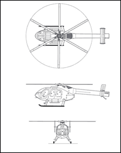
McDonnell Douglas MD600N C-FTAZ
Zama Lake, Alberta, 25 nm NW
The Transportation Safety Board of Canada (TSB) investigated this occurrence for the purpose of advancing transportation safety. It is not the function of the Board to assign fault or determine civil or criminal liability. This report is not created for use in the context of legal, disciplinary or other proceedings. See Ownership and use of content. Masculine pronouns and position titles may be used to signify all genders to comply with the Canadian Transportation Accident Investigation and Safety Board Act (S.C. 1989, c. 3).
Summary
The pilot of Rupert's Land Operations Inc. McDonnell Douglas Helicopters Inc. (MDHI) MD600N helicopter (registration C-FTAZ, serial number RN011) was conducting heli-slinging operations 25 nautical miles (nm) northwest of Zama Lake, Alberta (CFT9). The pilot had picked up the fifth and final bag of seismic equipment and was returning to the staging area, approximately 3 nm from the pick-up site. While en route, the tail boom separated from the fuselage and the helicopter crashed into a clearing about 1600 feet from the pick-up site. The sling load was still attached to the aircraft on a 115-foot longline. The tail boom was found about 240 feet from the main wreckage. The accident occurred at approximately 1400 mountain standard time. The pilot, the sole occupant, sustained fatal injuries. There was no post-impact fire.
Factual information
The pilot held a commercial helicopter pilot licence and was certified according to the existing Canadian Aviation Regulations at the time of the occurrence. The pilot also held a valid aircraft maintenance engineer licence but was not employed as an aircraft maintenance engineer at the time of the occurrence. The pilot had a total of 9827 hours of helicopter flight experience at the time of the occurrence. Of that time, 2056.6 hours were logged on the MD600N helicopter. The pilot's most recent pilot proficiency check flight was conducted on 30 June 2005.
Records indicate that the aircraft was certified, equipped, and maintained in accordance with existing regulations and approved procedures. The weight and centre of gravity were within prescribed limits and not considered to have been contributory to this accident.
Weather at the time of the occurrence was conducive to visual flight rules (VFR) operations and was not considered to have been contributory to this accident.
The MD600N helicopter is equipped with the no-tail-rotor (NOTAR) system. This system uses directed air generated by a variable-pitch fan and a direct jet thruster to provide for anti-torque and directional control. In forward flight, directional control is provided by a combination of the vertical stabilizers and the direct jet thruster.
Design
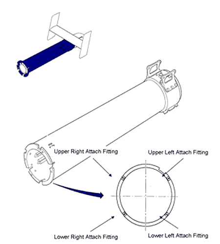
The tail boom of the helicopter was attached to the fuselage at four locations by two, 5/16-inch-diameter bolts at the upper right and lower left positions and two, 3/8-inch - diameter bolts at the upper left and lower right positions (see Figure 2).
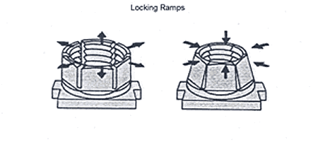
The forward flange of the tail boom was bolted against the aft surface of the aft fuselage ring frame. The bolts were attached from the aft side of the forward flange of the tail boom. Each bolt head was lock wired to the radius block following tightening to final torque. The bolt was secured by a fastener assembly, comprised of a locknut (see Figure 3) attached to a retainer plate and riveted inside an attach fitting.
The four attach fittings were connected to the aft ring frame, which transfers the tail boom loads to the main airframe longerons. The locknuts are designed to allow the tail boom attach bolts to be removed on a repetitive basis without compromising the locking ability of the locknuts.
Upper Right Attach Fitting
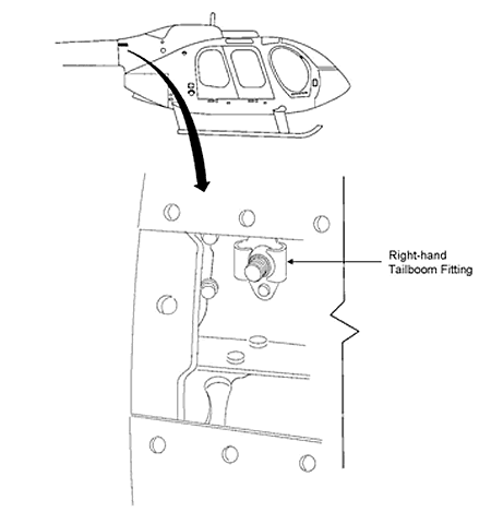
The upper right attach fitting (see Figure 4) had separated due to the failure of the fitting. This in turn caused the failure of the attaching section of the fuselage ring frame. Of the two brackets that attach the fitting to the frame, one was missing and the second had fractured through one of the attaching rivet holes.
The fracture surfaces of the fitting appeared fresh and had a bright, crystalline appearance, with the exception of the crack surfaces between the two inboard rivet holes, which were coated with a black deposit. The deposit was determined to be fretted material. The complete failure of the bathtub fitting was consistent with the fatigue cracking through more than 95 per cent of the cross section of the fitting. The failure of the fitting resulted in the transfer of load to the aft ring structure, causing a section of the ring structure to separate during the final failure sequence.
Upper Left Attach Fitting
The upper left attachment bolt had pulled through the locknut. The threads of both the bolt and the locknut show damage consistent with a shearing motion. The upper left attachment bolt was fully engaged and extended through the nut by three to four threads. The locknut has six flexible beams (Figure 3 locking ramps) that provide the locking function as the bolt is tightened. One of the six beams was broken off, and a second beam was cracked but still attached; it broke off when slight finger pressure was applied. A third beam had several small cracks emanating from the inner surface. Cracking was evident in all three beams emanating from the roots of the internal threads, initiating and leading from the corners formed by the intersection of the threads with the vertical cut slots. The TSB Engineering Laboratory confirmed the cracking was due to fatigue. The exposed surfaces of the cracks had rub markings, which destroyed any fine detail of the nature of the fatigue.
Lower Left Attach Fitting
The lower left attachment bolt had also pulled through the locknut. Damage to the threads of both bolt and locknut was consistent with tension overload. The extent of damage was consistent with a full engagement of the bolt in the locknut with two to three threads extending beyond the end face of the nut. One of the flexible beams had broken off in the course of the bolt pulling through. Examination of the fracture surface found that the features were consistent with overload failure. A slight bend was observed in the bolt, indicating that the loading had a bending component at the time of separation.
Lower Right Attach Fitting
The lower right attach fitting remained intact until the last stage of tail boom separation. The bolt had partially pulled through the nut before being exposed to a high bending load that resulted in a transverse fracture of the bolt in the plane of the first thread. There was no indication of pre-cracking or a progressive failure of any kind.
Attach Fitting Testing
The bolts and locknuts from three sister ships (C-GAAJ, C-GDEN, and C-GTSL) as well as a new set supplied from the manufacturer were tested by the TSB Engineering Laboratory to determine the failure condition. In general terms, all locknut threads failed at loads less than the specified failure loads of the bolts. The results are recorded in Table 1 as the applied tensile load required to pull the bolts through their respective locknuts.
Table 1. Pull-out loads |
| Installation | Location | Pull-out Load (lb) | Percentage of tensile strength |
| 5/16-inch-diameter bolts | |||
| C-GAAJ | Left-hand lower | 11 700 | 87 |
| C-GDEN | Left-hand lower | 10 300 | 76 |
| C-GTSL | Left-hand lower | 11 200 | 83 |
| OEM | New | 10 820 | 80 |
| 3/8-inch-diameter bolts | |||
| C-GAAJ | Right-hand lower | 13 390 | 64 |
| C-GDEN | Right-hand lower | 13 520 | 65 |
| C-GTSL | Right-hand lower | 12 930 | 62 |
| OEM | New | 13 660 | 62 |
Loading was axial, with a minimum of four or five complete threads extending beyond the end of the nut. The similarity of the results would suggest that prior usage had little effect on the pull-out values. The pull-out loads are less than the breaking strength of the bolts, but are in excess of the expected flight loads at the fastener locations determined by the manufacturer. MDHI provided the following flight test values for the maximum tail boom attachment point tension loads: upper left - 3992 pounds, upper right - 3844 pounds, lower left - 2176 pounds, and lower right - 2390 pounds.
The manufacturer's maximum recorded test load results for the tail boom fastener locations indicated that the maximum measured fatigue spectrum load at the upper left tail boom attachment point was 3992 pounds. This occurred during a gust loading condition. MDHI calculated that the load at the upper attachment point would increase to 5609 pounds if this gust loading condition were to occur with no upper right tail boom attachment point.
Bolt and Locknut Lubrication
A post-occurrence inspection of C-GTAZ at the TSB regional office revealed the presence of accumulated dirt and grime in the vicinity of the attach fitting. The threads on the bolts and locknuts showed residue of a grease-like lubricant. New locknuts provided to TSB Engineering Laboratory by MDHI were found to have a quantity of dry lubricant painted on the thread surfaces. The MDHI Maintenance Manual instructions for the removal and re-installation of the tail boom do not make specific reference to the replenishment of the lubricant. Many operators have taken it upon themselves to facilitate the reassembly by using a grease-based lubricant containing molybdenum disulphide on the threads of the fasteners.
Lubrication can induce higher tensile loading in the bolts due to the reduction in the frictional resistance during the torquing operation. Tests were performed using an internally strain-gauged, instrumented bolt, with and without the presence of grease on the threads of the bolt and locknut. The 3/8-inch-diameter size was selected and an experimental rig prepared to enable the effect to be examined at the 180 to 220 inch-pounds applied torque as specified in the MDHI Maintenance Manual.
Measured tensile loads in the bolt for an applied torque of 180 and 220 inch-pounds were 3500 and 4150 pounds for the dry, and 3900 and 4700 pounds for the lubricated threads, respectively. The respective 11.4 and 13.25 per cent increase in the applied tensile loading with the wet configuration was below the minimum failure load of the fasteners (approximately 11 000 pounds).
Service Bulletin and Airworthiness Directive History
In 2001, MDHI issued Service Bulletin (SB) SB600N-036. This bulletin, entitled "Tailboom Assembly Attach Fitting One Time Inspection and Repair," addressed the issue of reported cracking of the upper right-hand tail boom attach fittings. Part 1 of the SB required that the inspection requirements of the bulletin be accomplished within the next five hours of helicopter operation or within 30 days of the issue of the bulletin. Should the inspection of the helicopter as per Part 1 not be satisfactory, Part 2 of the bulletin was to be implemented. Part 2 of the SB required that the inspection and repair requirements of this bulletin be accomplished within the next 25 hours of helicopter operation or within 90 days of the issue of the bulletin.
The Federal Aviation Administration (FAA) issued an Airworthiness Directive (AD), AD2001-24-51, that required the inspection of the upper tail boom attachments, nut plates, and angles for cracks or thread damage within five hours time-in-service (TIS). Should cracks or thread damage be observed, repair or replacement of any damaged or cracked parts was required before further flight. Additionally, this AD required a 25-hour total TIS inspection of the tail boom attachment. This 25-hour inspection required the use of a borescope to inspect the upper tail boom attachments for cracks through the upper access covers.
In January 2002, the FAA approved an Alternate Method of Compliance (AMOC) for AD2001-24-51. The AMOC stated that, during the initial inspection, the area may be viewed through an inspection hole in the fairing. The upper tail boom attachment covers and tail boom would not have to be removed. Additionally, bright light and visual inspection may replace the use of a light and a 10x or higher magnifying glass. The use of a borescope may also be replaced with a bright light and visual inspection as per the instructions outlined in the AD.
In 2003, MDHI issued SB600N-039. This bulletin addressed the inspection of tail boom attach fittings and upper longerons. Part 1 of the bulletin required that an aft fuselage inspection hole be installed and an initial inspection of the aft tail boom attach fittings be done within 100 hours of receipt of the bulletin. Part 2 required that the attach fittings be subject to recurring inspections at 25 flight-hour intervals for the upper tail boom attach fittings and at 100 flight-hour intervals for the lower tail boom attach fittings. This inspection required the use of a bright light to visually inspect the attach fittings for cracks or damage. SB600N-039 did not specify that the fitting was to be cleaned before inspection.
According to the technical record of the occurrence helicopter, SB600N-036, SB600N-039 and AD2001-24-51 had been complied with. The most recent inspection of the aircraft was on 17 February 2006, approximately 70 flight hours before the occurrence. During this inspection, AD2001-24-51 and SB600N-39 were complied with. Additionally, the special 25-hour inspection of the tail boom attach fittings was done. A 300-hour replacement of the tail boom attach bolts was completed.
The company daily inspection checklist required that the SB600N-039/AD2001-24-51 inspection of tail boom attach fittings be completed by the pilot-in-command before accepting the aircraft and every 25 hours thereafter while under his command authority.
The pilot had received training and authorization to conduct inspections as per SB600N-036 and SB600N-039 on 06 June 2005. The pilot had subsequently checked off the daily inspection completed box in the aircraft journey logbook, indicating the AMOC had been complied with.
Technical Bulletin (TB) TB600N-007 was issued by MDHI on 12 January 2004. This bulletin provided information regarding the modification of the fuselage aft section and tail boom including the use of stainless steel attach footings. Compliance with this technical bulletin was at the owner's/operator's discretion, and would dispense with the requirement for the recurring inspections as per SB600N-039. Should this technical bulletin not be completed, the aircraft could remain in service by continuing the recurring inspections as indicated by SB600N-039. Component replacement kits were not available until August 2005. The company had received and installed one kit, and two additional kits were on back order. C-FTAZ did not have TB600N-007 incorporated at the time of the occurrence.
MDHI has provided a list of 20 field reports of MD600N aft fuselage discrepancies. Twelve were found to have developed crack in the upper right aluminum fittings. These cracks were discovered during periodic Service Bulletin inspections. One of these twelve reports also reported a broken upper right-hand bolt. Each of these aircraft had the cracked fitting replaced with a steel fitting. The remaining eight other incidences of cracked upper right angles were not considered critical.
Analysis
The analysis will focus on the sequence of failure of the tail boom attachment fittings and the limitations of repetitive inspections.
Fatigue cracking of the upper right attach fitting occurred, resulting in the transfer of loads to the aft ring structure and remaining three tail boom attach fittings. The resulting onset of fatigue in the locknut flexible beam elements of the upper left attach fitting, which compromised the strength of the fastener, allowed the upper left bolt to pull out of the locknut. Failure of the two upper attach fittings caused overload and separation of the lower two attach fittings. This resulted in the detachment of the tail boom and loss of aircraft control. Safe recovery following this type of structural failure would be unlikely.
The 25-hour inspection, as mandated by AD2001-24-51, required the use of a borescope in order to inspect the upper fittings. This was later augmented by the AMOC, which allowed the operator to conduct visual inspections of the tail boom attach fittings. The 25-hour visual inspections did not identify damage to the tail boom attach fittings before structural failure. Additionally, debris around the fitting may have obscured the crack in the fitting.
The following TSB Engineering Laboratory report was completed:
- LP 022/006 – Bolts and Anchor Nuts
This report is available from the Transportation Safety Board of Canada upon request.
Findings as to Causes and Contributing Factors
- The attach fitting at the upper right attachment point of the tail boom failed in fatigue. The transfer of loads to the adjacent aft ring structure resulted in the cascading failure of the remaining three tail boom attach fittings and separation of the tail boom from the fuselage.
- Aircraft control was lost following separation of the tail boom. Safe recovery following this type of structural failure was unlikely.
- The 25-hour visual inspections allowed by the Alternate Method of Compliance (AMOC) did not identify damage to the tail boom attachment fittings before structural failure.
Safety action
Safety action taken
Rupert's Land Operations Inc. voluntarily grounded its fleet of MD600N helicopters pending the replacement of the attachment fittings as per Part 2 of Service Bulletin SB600N-43.
On 13 April 2006, McDonnell Douglas Helicopters Inc. (MDHI) issued SB600N-043 requiring a borescope inspection of all four attach fittings. Within 25 hours of receipt of the bulletin, the attach fittings are to be replaced. On 13 April 2006, MDHI issued Technical Bulletin TB600N-007R1 regarding modification of the fuselage aft section and tail boom to strengthen the tail boom attach fittings and upper longerons.
On 27 April 2006, the Federal Aviation Administration (FAA) issued Airworthiness Directive (AD) AD2006-08-12. This AD requires that additional inspection holes be created in the aft fuselage skin panels, and that inspection of the upper and lower tail boom attach fittings, the upper longerons, and angle and nut plates for cracks be accomplished. It also requires, within a specified time, replacing the aluminum upper right tail boom attach fitting with steel fittings, painting the inspection area, and replacing existing nut plates.
This report concludes the Transportation Safety Board's investigation into this occurrence. Consequently, the Board authorized the release of this report on .


