
Rail transportation safety investigation report R22D0106
Non–main-track derailment
Canadian National Railway Company
Train M32621-11
Mile QM 192.1, CSX Transportation Montreal Subdivision
Near Huntingdon, Quebec
The Transportation Safety Board of Canada (TSB) investigated this occurrence for the purpose of advancing transportation safety. It is not the function of the Board to assign fault or determine civil or criminal liability. This report is not created for use in the context of legal, disciplinary or other proceedings. See Ownership and use of content.
-
Table of contents
Summary
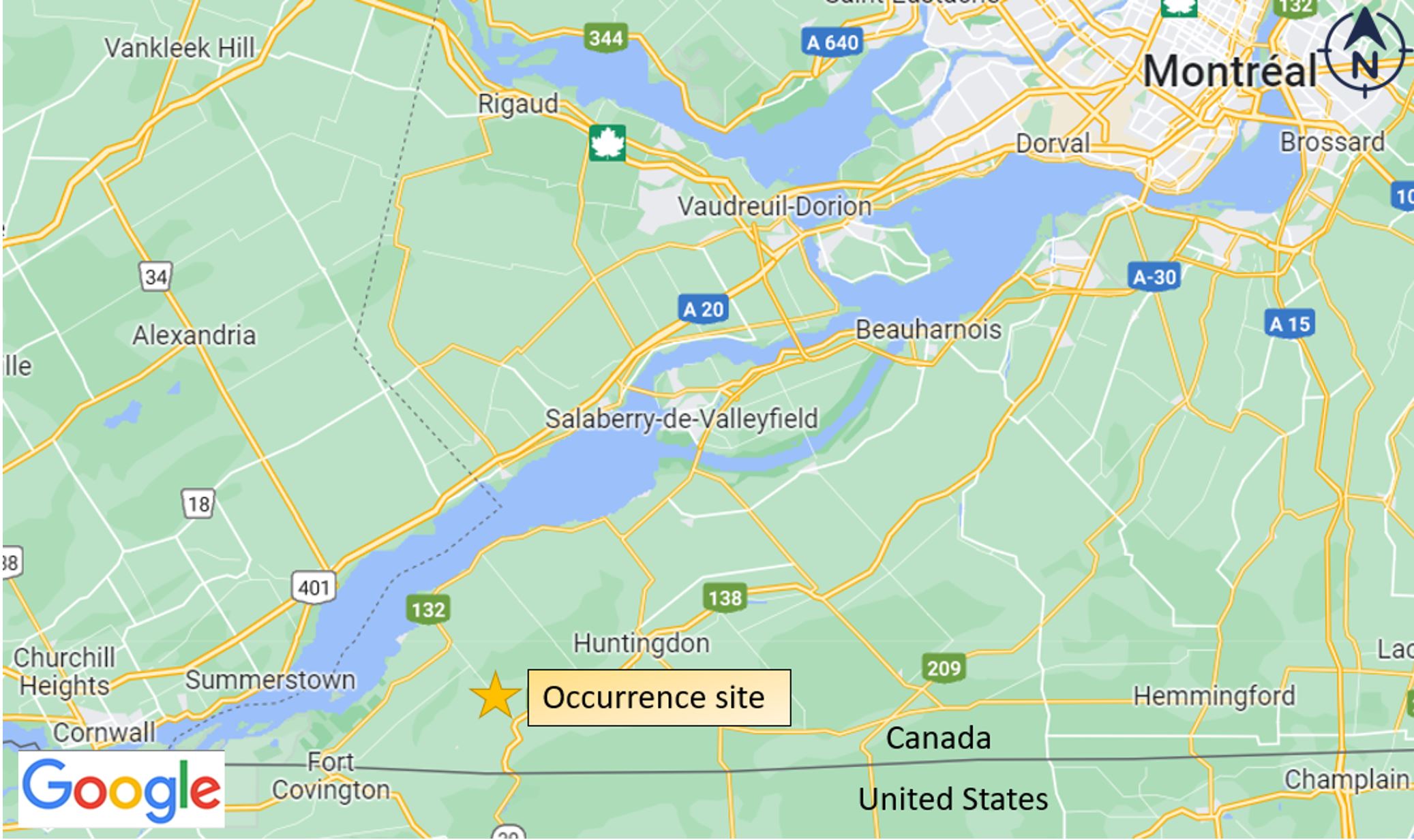
On 11 December 2022 at approximately 1912 Eastern Standard Time, Canadian National Railway Company train M32621-11 (CN M326) was travelling northward at approximately 22 mph in the Carr siding on the CSX Transportation Montreal Subdivision near Huntingdon, Quebec. As the train approached the switch leading to the main track at Mile QM 192.1 (White Station), the 2 head-end locomotives and 6 intermodal platforms derailed while travelling over a switch point derail. There were no injuries.
1.0 Factual information
1.1 The occurrence
On 11 December 2022, CSX Transportation (CSXT) train M621 (CSXT M621) left the Massena Terminal in New York (United States) at approximately 1730. The train, operated by a CSXT crew, consisted of 2 locomotives and 37 cars, including 3 cars carrying 13 intermodal platforms loaded with containers. Footnote 1 The train was 3223 feet long and weighed 3031 tons.
At around 1817, CSXT M621 arrived at the Carr siding at Mile QM 191 of the Montreal Subdivision, near Huntingdon, Quebec (Figure 1), the designated train interchange point between CSXT and the Canadian National Railway Company (CN). Following standard procedure, the CSXT crew stopped the train on the siding so that the head-end locomotives were located in the middle of the siding.
Earlier that day, at about 1500, CN train M327 (CN M327), operated by a CN crew, had left Taschereau Yard in Montréal, Quebec, bound for the interchange point. Approaching the Carr siding, the crew stopped CN M327 on the main track, with the head-end locomotives opposite those of CSXT M621 (Figure 2). This method facilitates the transfer of train crews while keeping the northern end of the siding (White Station) clear as much as possible.

At approximately 1854, the 2 crews took control of their respective trains in order to return to their initial terminal. CN M327, taken over by the CSXT crew (now referred to as CSXT L034), left the interchange point and headed southward after obtaining authorization from CSXT’s rail traffic controller (RTC) in Jacksonville, Florida (United States).
CN’s conductor and locomotive engineer (LE) boarded train CSXT M621 (now referred to as CN M326) and performed the usual pre-departure checks. They radioed CSXT’s RTC to obtain authorization to leave the siding and take the main track northward.
After the conductor had obtained authorization from the RTC to occupy the main track, which is governed by the occupancy control system (OCS), Footnote 2 the LE on train CN M326 left the cab of the lead locomotive (CN 2237) to go to the second locomotive (CN 5719) to check that the multiple-unit operating controls were correctly set. On his return, he moved the reverser handle to the forward position, released the independent brake and placed the throttle in notch 1. He then entered the dual-tone multi-frequency (DTMF) sequence Footnote 3 on the locomotive railway radio, intending to line the radio-controlled switch Footnote 4 from the main track to White Station Footnote 5 in the position that would permit the train to enter the main track. The switch target light then went from red to green, and an audio confirmation message from the power-assisted switch (PAS) system Footnote 6 was transmitted over the railway radio. At approximately 1912, while travelling at 22 mph, the train derailed when it passed over the switch point derail Footnote 7 north of the siding (Figure 3). At that time, a train-initiated emergency brake application occurred.
At the time of the occurrence, the temperature was −10 °C, the sky was overcast, and it was snowing lightly.
There were no injuries. No cars carrying dangerous goods were involved in the derailment. About 400 litres of diesel fuel spilled from the locomotives.
1.2 Site examination
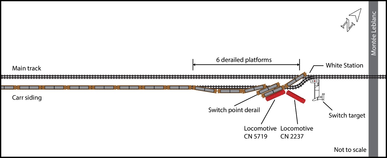
As a result of the derailment, lead locomotive CN 2237 partially sank into the ground on the east side of the track, in a 45-degree inclined position. Locomotive CN 5719 rolled onto its side (Figure 4).

The coupler head behind locomotive CN 5719 broke, and the first five-pak car came to rest straddling part of the main track. Five intermodal platforms derailed, as did the truck on the first platform of the second five-pak car.
Part of the siding and main track was damaged at the point of derailment.
1.3 Recorded information
The TSB collected and reviewed the event recorder data from the locomotives involved, the forward-facing camera recording and the locomotive voice and video recorder (LVVR) data from the lead locomotive.
According to the locomotive event recorder data, the train was proceeding at 22 mph and accelerating before the derailment. No emergency braking was initiated by the LE before the derailment.
The data from the LVVR on the lead locomotive consisted only of video recordings. There was no audio recording from the microphones inside the cabin because of a problem related to the georeferencing system.Footnote 8 That function allows the cab voice recording to be deactivated when the train is operating in the United States in order to comply with U.S. regulations.Footnote 9 As the accident occurred near the Canada–U.S. border, the system prevented the activation of the microphones in the cab.
1.4 Crew information
The crew members of CN M326 were qualified for their respective positions and met established rest and fitness requirements. Both were familiar with the territory; they had been working on that assignment for about a month and had already worked on it in the past. The LE had more than 15 years of experience, and the conductor had over 7 years of experience. They had started their shifts on CN M327 at 1350 on 11 December 2022 at CN’s Taschereau Yard.
1.5 Subdivision and track information
CSXT’s Montreal Subdivision extends from the Canada–U.S. border at Fort Covington, New York (United States) at Mile QM 183.1 to Adirondack Junction at Mile QM 238.4, near Châteauguay, Quebec. This is non-signalled territory, Footnote 10 where movements operate under OCS rules. An RTC located in Jacksonville directs traffic on the subdivision, issuing clearances, track occupancy permits, general bulletin orders, and other necessary instructions. The main track is class 3, Footnote 11 and the maximum allowable operating speed in the time table is 25 mph. On average, 4 trains run daily on the subdivision. In 2022, there were 2.2 million gross ton-miles per mile of track recorded on this subdivision.
In the vicinity of the derailment site, the Carr siding is 10 007 feet long, with distinctive station names at each end (Arnold to the south and White to the north). The maximum allowable operating speed in this siding and on the turnouts connecting it to the main track is 25 mph. The track is tangent, with no significant gradient. The rails and ties were in good condition. There is a level crossing near the north end at White Station.
1.6 Interchange procedures between Canadian National and CSX Transportation trains
CN and CSXT interchange trains on an almost daily basis on CSXT’s Montreal Subdivision. Typically, CN crews working on this assignment are called out in the late morning on CN M327 and report to their home terminal in Montréal in the early afternoon. The train crew’s call time is established according to the switching operations to be performed en route and coordinated with CSXT so that the 2 trains can reach the interchange point at approximately the same time.
1.7 Switch systems
1.7.1 Description of occupancy control system switch systems in Canada
In Canada, the majority of OCS main-track switches are hand-operated (Figure 5). Footnote 12 Operating procedures for these switches are detailed in Rule 104 of the Canadian Rail Operating Rules (CROR). Rule 104(q) states the following:
The employee handling a main track hand operated switch in non-signalled territory must, from the location of the switch, communicate with another employee to confirm the position in which the switch has been left, lined and locked. The employee receiving this report must repeat it back to the employee who handled the switch. Communication may be achieved by personal contact, radio or telephone. A lone employee unable to communicate with any employee other than the RTC, must communicate with the RTC. Footnote 13

1.7.2 CSX Transportation power-assisted switch system at each end of the Carr siding
In 2015, CSXT commissioned 3 PAS systems on its Montreal Subdivision, notably at each end of the Carr siding. These are dual-control switches Footnote 14 linked to an interface enabling them to be controlled by radio from the locomotive cab or using a portable railway radio. Visual indication of the switch position is provided by an electronic target with a coloured light (Figure 6).

In accordance with standard railway operating practices in Canada, main-track switch targets are considered a visual reference that, in addition to indicating the switch’s position, assist the train crew in determining the exact location of the switch.
To activate a PAS, a DTMF sequence must be transmitted on the subdivision’s standby channel over the railway radio. Each PAS has 2 separate sequences, enabling the switch to be operated depending on the routing. A sign on the approach to the switch reminds crews that the DTMF sequence must be transmitted. Once the sequence has been transmitted, the position of the switch is confirmed by the colour of the light on the electronic switch target (Table 1), as well as by an audio confirmation message transmitted over the railway radio.
| Switch target light | Switch position | Route |
|---|---|---|
| Green | Normal | Direct route (main track) |
| Yellow | Reverse | Siding |
| Red | Out of correspondence | None |
The system is equipped with a timer, a track occupancy circuit, and a switch heater. The circuit area is delimited by trackside signs. Once the DTMF sequence has been transmitted, the movement has 10 minutes to reach the occupied circuit. After the time limit has expired, or as soon as a movement passes the switch, the switch target light reverts to red. The system increases operational efficiency because crew members do not need to leave the locomotive cab to operate the switch.
1.7.3 CSX Transportation special instructions on the use of power-assisted switches
The use of CSXT PAS is governed by special instructions included in the Montreal Subdivision time table and in the CSXT Canadian Operations Manual. These special instructions describe the various DTMF sequences in effect, the procedures for transmitting them on the railway radio, and the specific operating features of the switch system and electronic target. The instructions also contain the procedures that apply in cases where the switch has to be hand operated following a system malfunction.
These special instructions do not require Footnote 15 train crew members to confirm the following with each other:
- the switch position required for the route to be taken;
- the DTMF sequence to be used; and
- validation of the confirmation details transmitted by the PAS system after the commands have been executed by the system.
1.7.4 Derail linked to the power-assisted switch system
The Carr siding is equipped with power-operated derails at both ends. These are double-point derails located beyond the fouling point on the main track, some 450 feet from the switch, and fitted with switch heaters (Figure 7).

These derails, which are linked to the PAS system, protect the main track from any uncontrolled movement of rolling stock, in compliance with CROR Rule 112(a)(i). When the switch is lined in the normal position, or when it is “out of correspondence,” the derail is in the derailing position (Table 2).
| Switch target light | Switch position | Derail position | Route |
|---|---|---|---|
| Green | Normal | Derailing | Direct route (main track) |
| Yellow | Reverse | Non-derailing | Siding |
| Red | Out of correspondence | Derailing | None |
1.7.5 Derail identification
Section E of the Transport Canada–approved Rules Respecting Track Safety specifies the minimum requirements for various track appliances, including derails. According to the regulations, “Each derail must be clearly visible. When in a locked position a derail must be free of any lost motion which would allow it to be operated without removing the lock.” Footnote 16
CROR Rule 104.5(a) states the following:
The location of each derail will be marked by a sign, unless otherwise directed by special instructions. Employees must be familiar with the location of each derail. Footnote 17
In the Carr siding:
- there is no sign indicating the presence of derails;
- the special instructions in effect at the time of the occurrence did not mention the presence of derails; and
- the derails are not equipped with a separate target to indicate whether they are in the derailing or non-derailing position.
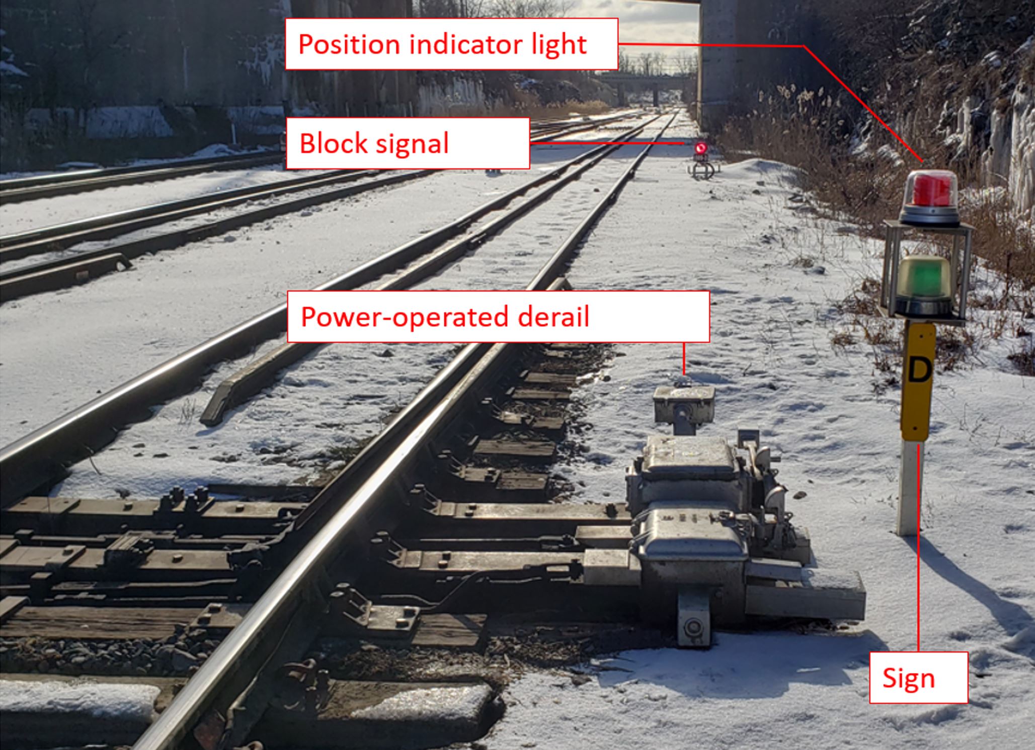
Most radio-controlled, power-assisted derails linked to railway signals in Canada are equipped with a separate position indicator light and a reflectorized sign (Figure 8).
1.7.6 Visibility of the switch target and derail
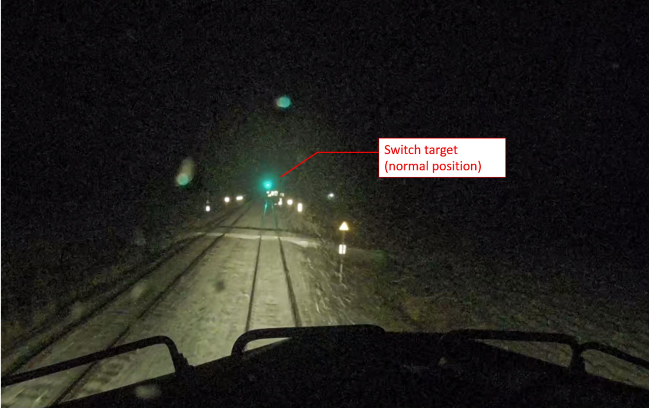
In this occurrence, once the switch moved to the normal position, the electronic switch target light, which had turned green, was clearly visible (Figure 9) but it was impossible to distinguish the position of the derail switch points.
1.8 Taking over train CN M326
1.8.1 Pre-departure preparations
The CN crew arrived at the Carr siding interchange point at about 1851 on train CN M327. The conductor and the LE boarded the CN M326 lead locomotive at approximately 1854. As soon as they were on board, the crew settled into their respective workstations and carried out several tasks:
- The LE ensured that all controls on the lead locomotive were properly adjusted.
- The LE selected the RTC channel on the railway radio.
- The conductor contacted the RTC and obtained OCS authorization for the train to leave the siding and enter the main track.
- At approximately 1906, the LE momentarily left the cab of the lead locomotive to go to the second locomotive to check that the multiple-unit operating controls were correctly set.
- The conductor verified the relevant documents relating to the movement.
- After returning to the lead locomotive cab, the LE immediately started the train.
- The conductor took several containers containing his meal out of his bag and used the locomotive’s microwave oven.
- As the LE gradually increased the train’s speed using the throttle, he checked the various switches on the locomotive console.
- The LE repeatedly checked the circuit-breaker panel behind him to ensure that the de-icing system was operating. Footnote 18
- While continuing to increase locomotive tractive effort, the LE referred to an assignment job aid to identify the DTMF sequence to place the switch in the appropriate position.
- As the LE was entering the selected DTMF sequence on the railway radio keypad, the conductor was standing near the console, talking with him.
1.8.2 Dual-tone multi-frequency sequence entered by the locomotive engineer
The LE consulted the job aid to identify the DTMF sequence used to line the train’s route so it could leave the siding and enter the main track (switch in reverse position and derail in non-derailing position). The LE selected the first DTMF sequence in the document and entered it on the railway radio keypad. That sequence was to place the switch in the normal position (switch in the position for the direct route and derail in the derailing position). Once the switch moved to the normal position, the electronic switch target light turned green, and the PAS system transmitted an audio message over the railway radio confirming the switch position for the direct route. The crew did not detect any anomaly with these indications, and the train continued on its way.
1.8.3 Divided attention and human performance
Attention is “a state in which cognitive resources are focused on certain aspects of the environment rather than on others.” Footnote 19 Divided attention is when a person’s attention is on “two or more channels of information at the same time, so that two or more tasks may be performed concurrently.” Footnote 20
The Federal Railroad Administration (FRA) of the United States defines attention as a behaviour that a person uses to focus the senses on information that matters outside the cab, inside the cab, or on the railway radio. Paying attention to information that is not important is a distraction because people have a limited attention span. Footnote 21 For an LE, focusing on what matters means focusing on what is critical at any given time, particularly:
- signal indications
- switch positions
- approaching crossings
- controlling train speed
- locomotive display system indications
- selecting railway radio channels
- communicating restrictions and fixed signal indications with the conductor
Humans have the ability to choose where to focus their attention in order to concentrate on what is important. However, dividing attention over several aspects results in reduced performance, which can contribute to an incident or accident. Footnote 22
2.0 Analysis
The data collected during the investigation showed that the 2 crew members were fit for work. No medical or physiological conditions, including fatigue, were reported to have affected their performance. The analysis will focus on the dual-tone multi-frequency (DTMF) sequences controlling the switch, the instructions for radio-controlled dual control switches in the occupancy control system, the identification of derail positions and locations, and the locomotive voice and video recorder.
2.1 The occurrence
On 11 December 2022, crews from CSX Transportation (CSXT) and Canadian National Railway Company (CN) interchanged trains CSXT M621 and CN M327 in the vicinity of Mile QM 191 of CSXT’s Montreal Subdivision, near Huntingdon, Quebec.
The CN crew took over train CSXT M621 (now designated as CN M326) in the Carr siding. Crew members performed the usual pre-departure checks and obtained authorization to leave the siding to enter the main track going northward. Once the train was underway, the conductor and locomotive engineer (LE) performed several tasks as the train headed for the north siding switch (White Station).
The LE entered a DTMF sequence on the locomotive’s railway radio, intending to set the switch at White Station in the position that would permit the train to enter the main track. The switch target light then went from red to green, and an audio confirmation message from the power-assisted switch (PAS) system, indicating that the switch was in the normal position, was transmitted on the railway radio.
At approximately 1912, the train derailed over the switch point derail at the north end of the siding. At the time, the train was proceeding at 22 mph and accelerating. When the head-end locomotives derailed, a train-initiated emergency brake application occurred. The 2 locomotives and 6 intermodal platforms left the track. The switch was lined in the normal position, and the linked derail protecting the main track was in the derailing position.
Finding as to causes and contributing factors
Train CN M326 derailed while leaving the Carr siding, when it passed over a switch point derail linked to a radio-controlled switch system as it prepared to enter the main track at about 22 mph.
2.2 Dual-tone multi-frequency sequence controlling the switch
In order to set the route for the train to leave the siding, the LE had to position the radio-controlled switch in the reverse position. The LE checked his job aid and selected the first DTMF sequence on it. When he entered the selected sequence, the radio-controlled switch lined up in the normal position (for the direct route) instead of in the reverse position for the siding. Because the derail and the radio-controlled switch system are linked, the derail is in the derailing position when the switch is in the normal position.
The crew only realized that the derail was in the derailing position when the train passed over it.
Finding as to causes and contributing factors
In an attempt to set the switch in the reverse position, the LE instead selected and entered the DTMF sequence to set the switch in the normal position for the direct route; the derail linked to the system then remained in the derailing position.
While the LE was checking the job aid to identify the appropriate DTMF sequence, the conductor was standing near the locomotive control console, talking with him. In addition, the LE was concerned about the performance of the locomotive’s windshield de-icing system, because he wanted to prevent ice from building up and reducing visibility. Therefore, his attention was also focused on the circuit-breaker panel behind the control console.
Finding as to causes and contributing factors
The LE’s attention was divided between the priority task of selecting and entering the DTMF sequence for lining the switch in the reverse position and the other activities taking place.
After the LE entered the DTMF sequence, the crew heard the radio message indicating that the switch was in the normal position and saw the switch target light change from red to green. These indications were accepted as correct by the crew. The green light, in this case, meant that the switch was lined for the direct route and was not an indication for the train to leave the siding. However, it was interpreted by the crew as a permissive indication, in the same way as a signal found in centralized traffic control system territory. As a result, the crew did not react, and the train continued to accelerate, reaching 22 mph before passing over the derail.
Finding as to causes and contributing factors
The train crew concluded that the auditory and visual confirmations issued by the PAS system corresponded to the required route for the train to leave the siding.
2.3 Instructions for radio-controlled switches in occupancy control system territory
The steps involved in selecting and entering the required DTMF sequence to control the radio-controlled switch were carried out by the LE without prior consultation with the conductor. Such consultation is not required by CSXT’s special instructions governing the use of PAS.
Other railways that use radio-controlled switches in non-signalled territory have implemented instructions for the use of these switches. These instructions specify that, before using a radio-controlled switch, crew members within hearing range must communicate with each other immediately before selecting and entering the DTMF sequence to confirm the desired route and the applicable sequence.
It is critical to correctly establish the required switch position before selecting and entering the DTMF sequence. CSXT’s special instructions on PAS do not require train crew members to confirm the following with each other:
- the switch position required for the route to be taken;
- the DTMF sequence to be entered; and
- the confirmation messages from the PAS system once the commands have been executed by the system (switch target light and radio message).
Such confirmation would be an additional safeguard to reduce the risk of an inappropriate DTMF sequence being used.
Occupancy control system in non-signalled territory is an approved method of train control defined by the Canadian Rail Operating Rules (CROR). However, it depends on human intervention, making it susceptible to human performance.
Finding as to risk
If train crew members are not required to confirm with each other the DTMF sequence to be used to properly line a radio-controlled switch and the switch position after it has been lined, an incompatible route could be established, increasing the risk of accidents.
2.4 Derails
Radio-controlled, power-assisted derails linked to railway signals are commonly used in Canada on yard tracks, spurs or sidings connected to main tracks, especially in signalled territory. These derails are generally equipped with a reflectorized sign and a position indicator light separate from the rail signal.
When the crew members of CN M326 were setting the train in motion, they were unable to visually ascertain the position of the switch points on the Carr siding derail at White Station due to the distance and darkness. Since the derail does not have a separate target to indicate its position, the crew has to rely on the colour of the electronic switch target light to mentally determine the derail’s position (green=derailing/yellow=non-derailing). The green light on the target, meaning that the switch is in position for the direct route and that the derail is therefore in the derailing position, can be a counter-intuitive indication for a crew located in the siding. In addition, there is no sign indicating the presence of a derail at this location, and the subdivision’s special instructions in effect at the time of the occurrence did not mention the presence of derails in the Carr siding.
Switches and derails are separate track appliances and should, in theory, be equipped with separate targets indicating their position. An additional indicator of the derail’s position would provide another visual cue that could have enabled the crew to realize that an incompatible route had been selected.
Finding as to risk
A derail that is not equipped with a sign and a separate target may not be easily identifiable from the cab of an approaching locomotive, increasing the risk of an accident.
2.5 Locomotive voice and video recorder
Data recorded by locomotive voice and video recorders (LVVRs) enable TSB investigators to determine, objectively and reliably, the possible role of human factors in a railway occurrence.
In this occurrence, analysis of the video recordings revealed and established a number of facts, including the positioning of the crew members, the tasks performed by each of them, their visual attention, and the actions of the LE as he entered the DTMF sequence for the PAS on the railway radio keypad.
Finding: Other
Analysis of video recordings from the locomotive voice and video recorder system was useful in helping to establish the sequence of events leading up to the accident.
In analyzing the data from the lead locomotive’s LVVR system, the TSB found that there was no voice recording from inside the cab. The TSB determined that this was a problem related to the georeferencing system, which allows the cab voice recording to be deactivated when the train is operating in the United States in order to comply with U.S. regulations. Because the accident occurred near the Canada–U.S. border, the system did not activate the audio recording from the microphones in the cab.
The lack of voice data from the locomotive cab’s LVVR system meant that it was impossible to determine the verbal communications between the train crew members during the sequence of events.
Finding: Other
The lack of audio recordings from the locomotive cab microphones limited the analysis of communications between the train crew members.
3.0 Findings
3.1 Findings as to causes and contributing factors
These are conditions, acts or safety deficiencies that were found to have caused or contributed to this occurrence.
- Train CN M326 derailed while leaving the Carr siding, when it passed over a switch point derail linked to a radio-controlled switch system as it prepared to enter the main track at about 22 mph.
- In an attempt to set the switch in the reverse position, the locomotive engineer instead selected and entered the dual-tone multi-frequency sequence to set the switch in the normal position for the direct route; the derail linked to the system then remained in the derailing position.
- The locomotive engineer’s attention was divided between the priority task of selecting and entering the dual-tone multi-frequency sequence for lining the switch in the reverse position and the other activities taking place.
- The train crew concluded that the auditory and visual confirmations issued by the power-assisted switch system corresponded to the required route for the train to leave the siding.
3.2 Findings as to risk
These are conditions, unsafe acts or safety deficiencies that were found not to be a factor in this occurrence but could have adverse consequences in future occurrences.
- If train crew members are not required to confirm with each other the dual-tone multi-frequency sequence to be used to properly line a radio-controlled switch and the switch position after it has been lined, an incompatible route could be established, increasing the risk of accidents.
- A derail that is not equipped with a sign and a separate target may not be easily identifiable from the cab of an approaching locomotive, increasing the risk of an accident.
3.3 Other findings
These items could enhance safety, resolve an issue of controversy, or provide a data point for future safety studies.
- Analysis of video recordings from the locomotive voice and video recorder system was useful in helping to establish the sequence of events leading up to the accident.
- The lack of audio recordings from the locomotive cab microphones limited the analysis of communications between the train crew members.
4.0 Safety action
4.1 Safety action taken
4.1.1 Transportation Safety Board of Canada
On 23 February 2023, the TSB issued Rail Transportation Safety Information Letter 01/23, “Missing audio channel in locomotive voice and video recorder (LVVR) data,” to Transport Canada (TC).
The information letter stated that, while playing back the LVVR data from 2 occurrences, Footnote 23 the TSB observed that the locomotive recordings did not contain in-cab audio.
To ensure compliance with the Locomotive Voice and Video Recorder Regulations, the information letter stated that TC may wish to verify the functionality of LVVR systems used by railway companies and confirm that all of the parameters required under these regulations are being correctly captured and recorded.
4.1.2 Transport Canada
On 19 April 2023, TC responded to the letter by stating that it had contacted the railways involved and that, in both occurrences, TC found that the companies had taken appropriate measures to ensure that the LVVR systems function in accordance with the requirements of the regulations.
TC also stated that it had developed a regulatory oversight plan. TC’s first area of focus was on the installation of LVVR systems and verifying compliance with procedures to ensure that companies meet privacy requirements. TC will keep the TSB apprised of any new developments.
4.1.3 CSX Transportation
Following the occurrence, CSX Transportation added the precise location of each fixed derail to its Montreal Subdivision time table. The information also specifies the normal position (derailing or non-derailing) of each derail.
This report concludes the Transportation Safety Board of Canada’s investigation into this occurrence. The Board authorized the release of this report on . It was officially released on .